
Abstract
In order to improve the efficiency of underground mining and tunneling operations and to realize automatic drilling, it is necessary to develop the automation system for large drill jumbos. This work focuses on one such mining drill jumbo which is actually a redundant robotic manipulator with eight degrees of freedom, because it has six revolute joints and two prismatic joints. To realize the autonomous drilling operation, algorithms are proposed to calculate the desired pose of the end-effector and to solve the inverse kinematics of the drill jumbo, which is one of the key issues for developing the automation system. After that, a control strategy is proposed to independently control the eight joint variables using PID feedback control approaches. The simulation model is developed in Simulink. As the closed-loop controllers corresponding to all joints are local and independent of each other, the whole system is not a closed-loop feedback control. In order to estimate the possible maximal pose error, the analysis of the pose error caused by the errors of the joint variables is conducted. The results are satisfactory for mining applications and the developed automation system is being applied in the drill jumbos built by Mining Technologies International Inc.
1. Introduction
In mining industry, drilling is a very important task. About 75% of the mineral materials are excavated underground using the drill and blast method [1]. Hence, the economic importance of efficient drill jumbos used for drilling task becomes evident. Different types of drill jumbos have been developed to accomplish the demands of higher production rates and better efficiencies in activities such as hard rock mining and tunnel construction [2]. Most drill jumbos in operation today are manually operated [3]. The manual operation of drill jumbos has some disadvantages. For instance, the operation efficiency is low, because the operators need to manually move the drill to the desired locations of the holes on the mine face using several joysticks. This is actually a “trials and errors” process due to the availability of several joints that can be actuated. Also, moving the drill feed to a specified angle is prone to errors, as it is done by the operator through visual inspection. A wrong angle of the drill hole may lead to undercutting or overcutting of rock mass, leading to significant increase in overall costs [3].
This work focuses on the development of the automation system for the drill jumbo as shown in Figure 1, which is built by Mining Technologies International Inc. (MTI). The kinematics chain of this drill jumbo can be described by Figure 2 from which one can find that there are six revolute joints and two prismatic joints. Hence, it is actually an 8-DOF redundant serial robotic manipulator, which has two more DOFs than required to achieve the desired position and orientation of the end-effector. The advantages of such a kinematic redundancy are to improve the flexibility and versatility of the manipulator and to allow for collision-free motion in the robotic workspace using the redundant DOFs.

The mining drill jumbo built by MTI.
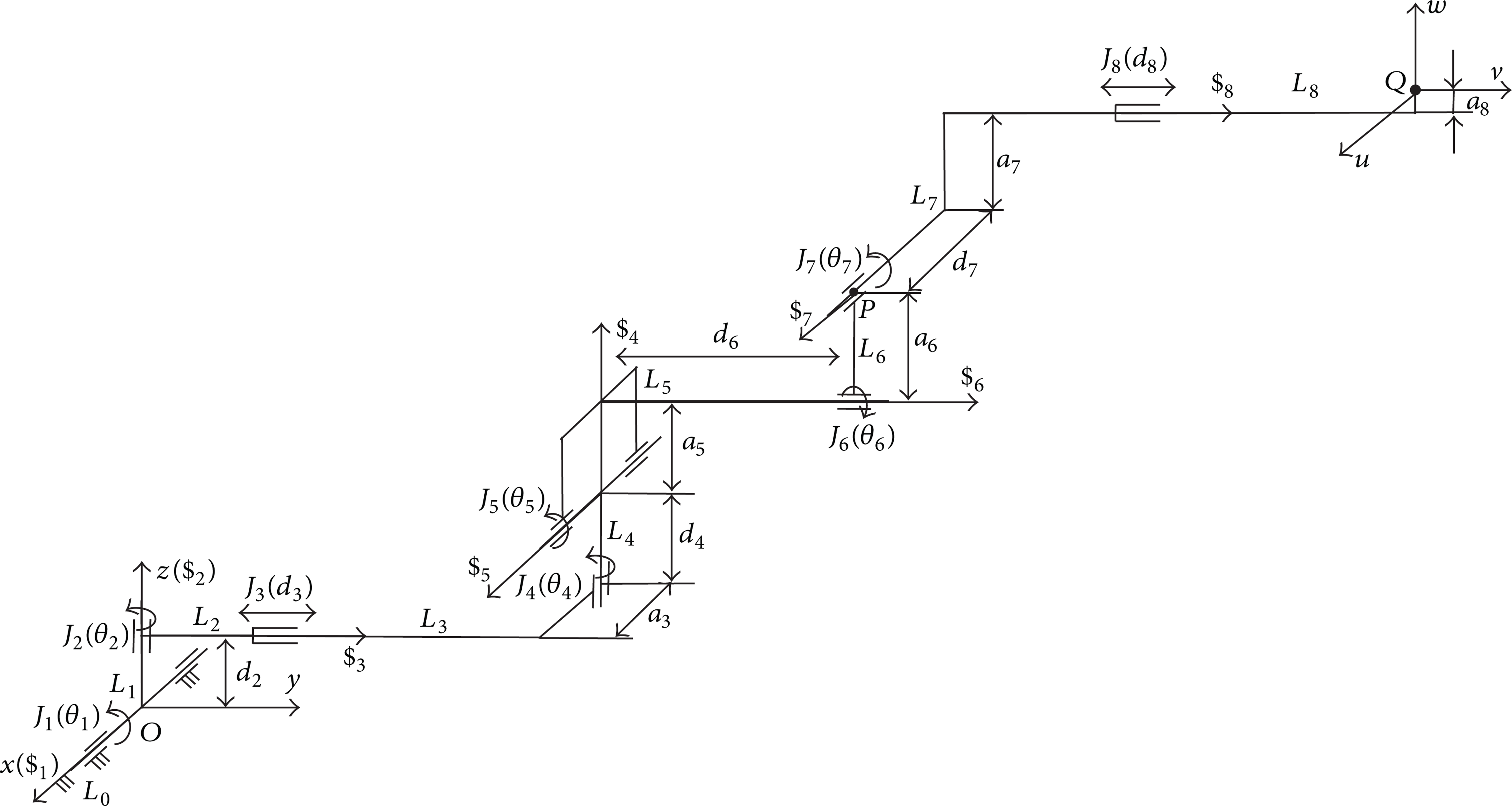
The kinematics chain of 6R-2P drill jumbo (home configuration).
The redundant manipulators have attracted many researchers in robotics to address their inverse kinematics [4–14]. Hence, several approaches for solving the inverse kinematic problem of redundant manipulators were proposed. Some approaches are essential for manipulator geometries with unknown inverse kinematic functions [8, 9]. But most researchers have solved the inverse kinematics problem based on the Jacobian matrix and its inverse or its pseudoinverse [6, 7]. Also, the closed-loop inverse kinematics algorithm has been widely discussed [10–14]. However, the closed-loop inverse kinematics algorithm mostly resolves the redundancy at the velocity level or at the acceleration level.
Although some research works on the redundant manipulators were conducted, to the best of the authors' knowledge, the inverse kinematics and workspace analysis on the drill jumbo as shown in Figure 1 have not been well addressed yet. The only relevant work is [1], which proposed some basic concepts. For the inverse kinematics, it just provided three equations at the velocity level. Any detailed and useful information about the inverse kinematics could not be found. Besides, it completely neglected the real situation with the drill jumbo inside the mine as shown in Figure 3. Hence, it did not provide some useful information about the relationship between the holes on the mine face and the drill jumbo as well as the slope angle η of the ground inside the mine.

The drill jumbo inside the mine.
The goal of this work is to develop a practical automation system for the large mining drill jumbo. Hence, how to quickly find a real solution for the inverse kinematics problem of the drill jumbo is the key issue for implementing a real time automation system. To this end, an efficient algorithm is proposed in this work to directly solve the inverse kinematics of the drill jumbo at the displacement level. The basic idea is to simplify the redundant 8-DOF manipulator to a 6-DOF nonredundant one [15–17] by choosing two joint variables as inputs.
In robotics, independent joint control is widely used in the motion control of robots [18–21]. Different researchers' control algorithms could be different from one to the other. But basically, their algorithms are based on the information of joints. In this work, in order to realize the autonomous drilling operation, a similar control strategy is proposed to independently control the eight joint variables using PID feedback control approaches. The hardware-in-the-loop simulation model is developed in Simulink and run on a real time xPC target machine. Considering that the whole system is not a closed-loop feedback control, it is necessary to conduct the analysis of the pose error of the end-effector to see whether the pose error of the end-effector is acceptable in the context of mining industry.
The remaining part of this work is organized in the following order: Section 2 illustrates the automatic drilling procedure. Section 3 calculates the desired poses for drilling the holes on the mine face. Section 4 addresses the kinematics problem. Section 5 focuses on the control strategy and simulation model of the automation system. Section 6 conducts the pose error analysis. Finally, conclusions are made in Section 7.
2. Automatic Drilling Procedure
As shown in Figure 4, the control procedure can be described as follows.

The automatic drilling procedure.
Step 1. Set the drill jumbo in the mine as shown in Figure 3 with a proper distance between the drill jumbo and the mine face so that the end-effector (the drill) can reach every hole on the mine face.
Step 2. Use a laser to make the mobile frame to coincide with the mine frame and calculate the pose (position and orientation) of the end-effector to drill hole j.
Step 3. Calculate joint variables based on the desired pose.
Step 4. Control joint variables so that the actual pose is within the tolerance of the desired pose.
Step 5. Drill hole j at its given depth.
Step 6. If all holes on the mine face have been drilled, stop. Otherwise (i.e., j < N, where N is the number of holes), go to Step 2 and drill the next hole.
3. Desired Pose
In practice, a surveyor determines the locations of the holes on the mine face as shown in Figure 5 before the drilling operation is performed. The position of hole j can be given as

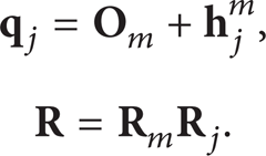
where

Hence,

where

Hence, ϕ
j
and ψ
j
can be solved as

The holes on the mine face.

The direction of hole j in the mine frame.
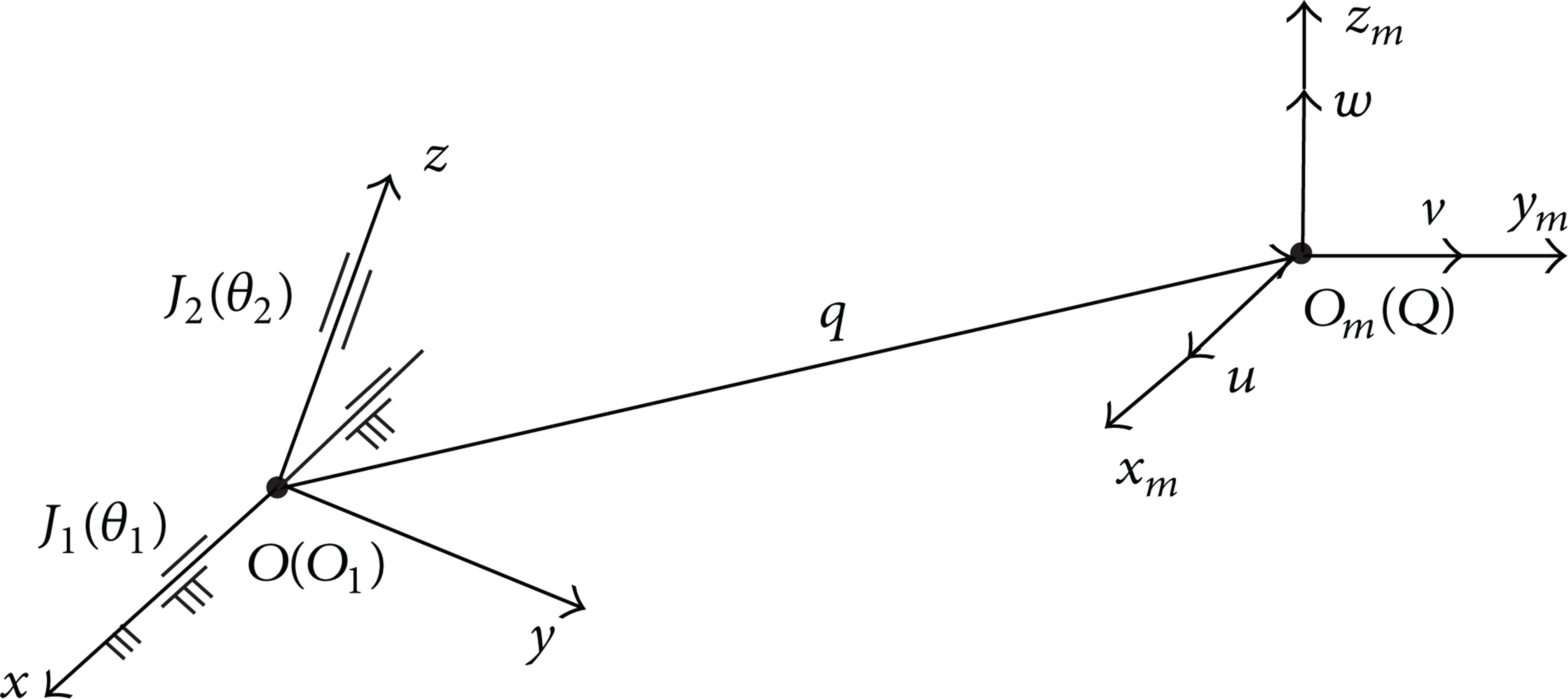
The relationship of coordinate systems.
4. Kinematics Analysis
When the position and orientation of the end-effector of the drill jumbo are given, it is necessary to determine the eight joint variables of the drill jumbo. Hence, it is necessary to conduct the kinematics analysis.
In robotics literatures, many researchers used the Denavit-Hartenberg method to define the coordinate systems [4–17]. This work uses the method of successive screw displacements [22]. Hence, only two frames are needed as shown in Figure 2. The reference frame Oxz is attached to the drill jumbo at the first joint J1 with the
Screw axis locations.
4.1. Direct Kinematics
The position of the end-effector Q at the home configuration as shown in Figure 2 can be given in homogeneous form as

Accordingly, the orientation of the end effector can be given as

where
4.2. Inverse Kinematics
The target position and orientation of the end effector in homogeneous form can be, respectively, given as
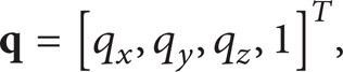

Referring to Figure 2, one finds that when the position and orientation of the end-effector are given, the position of point P at joint 7 is also available and can be given as

where

where

Expanding (13), one gets

where

Summing up the square of both sides and collect terms, θ4 can be eliminated. As a result, one gets

Now, let us consider the orientation of joint 7. Similarly, one gets

where

Expanding (18), one gets
From the first and third equations of (19), one gets
Substituting (20) into the third equation of (14), (16) and the second equation of (19), one gets

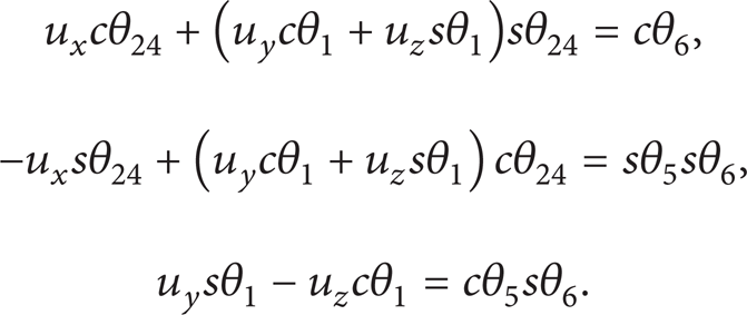
Substituting (11) into (21), one finally obtains a nonlinear system of three equations in five unknowns

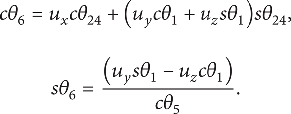
As mentioned in Section 1, the drill jumbo considered in this work has two redundant DOFs. Hence, it is logical to obtain the above nonlinear system of three equations in five unknowns. In order to solve θ7, one can obtain the following equation from (7):

Equating the elements, respectively, in row 3 and column 2 and row 3 and column 3 of the left and right matrices, one gets

In theory, there are infinite many solutions for this inverse kinematics problem. In mining application, the key is how to find a solution in the joint workspace quickly so that a “real time” control strategy can be accomplished. In order to solve the inverse kinematics problem, two random functions are used to produce a set of θ1 and θ5 from their working ranges (
The above algorithm has been implemented in MatLab. The program was run on an HP laptop with a 1.90 GHz AMD A4-3300M APU processor with Radeon (tm) HD Graphics. The average time used to solve the inverse kinematics of 47 holes is 0.0299 s. This shows that the proposed algorithm is fast enough to realize “real time” motion control in the context of underground mining application.
Details about how to maximize the workspace, how to avoid interference, and how to determine the range of the distance between the drill jumbo and the mine face were addressed in another paper.
5. Control Strategy and Simulation Model
When the joint variables are available by solving the above inverse kinematics problem, every joint can be controlled independently. Although all joints are driven by hydraulic actuators, the sensors used to measure the joint angles of the revolute joints and the displacements of the prismatic joints are different. But the controllers for all joint variables are similar and can be shown in Figure 8, which is a typical PID feedback control model [23] with the following transfer function:
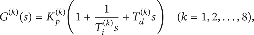
where
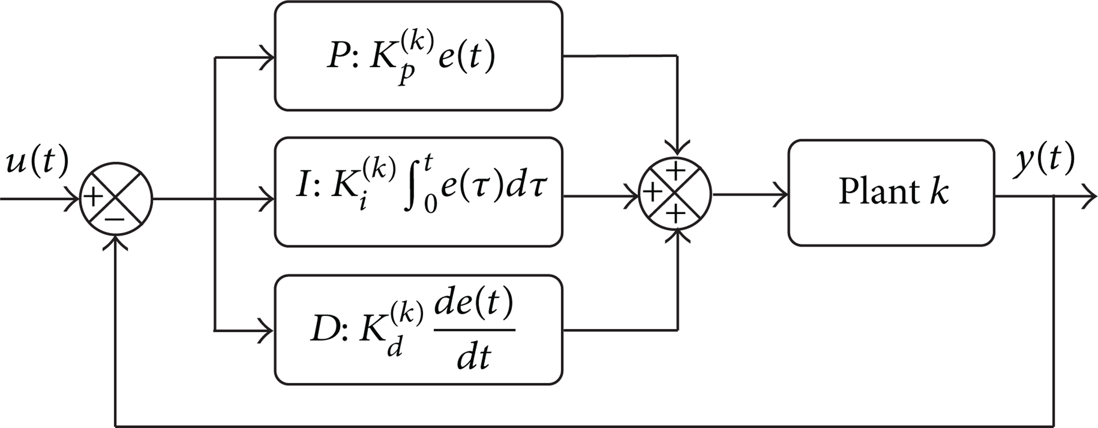
The PID feedback control model of joint J k .
The hardware-in-the-loop simulation model of the drill jumbo is developed in Simulink. The simulated drill jumbo is shown in Figure 9. Every joint in the model is actuated with a hydraulic actuator module. Take the first joint (i.e., the boom lift joint) as an example. Its hydraulic actuator block diagram is shown in Figure 10, which consists of a hydraulic cylinder with a damping source, position sensor, hydraulic pipes, a 4-way hydraulic valve, power unit, mechanical ports, and a PID controller. The block diagram of the power unit is shown in Figure 11, which consists of an ideal angular velocity source, a variable-displacement pressure-compensated pump, hydraulic reference and source, hydraulic pipes, and input signal saturated to a specified value. The hydraulic cylinder model chosen for the simulation is of a dual-acting type. The translational damper is added to its ports to mimic the damping in a real cylinder. The actual position of the hydraulic cylinder piston is traced on a simulated oscilloscope using Simulink variable time step solver. This is compared with the expected position of the piston by tracing the input signal on the same oscilloscope.

The simulated drill jumbo.

The hydraulic actuator model with a closed-loop PID controller for the boom lift joint.
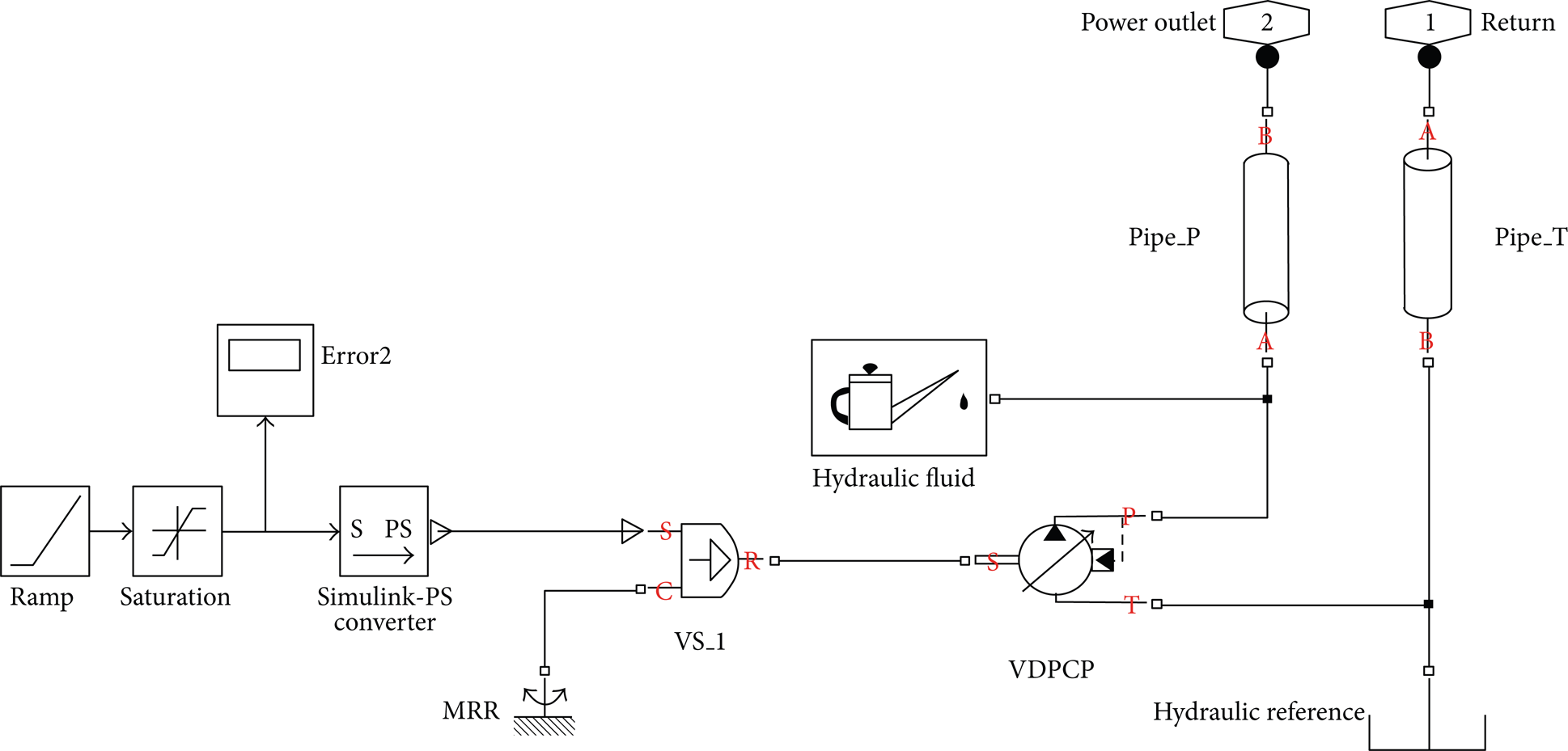
The power unit of the hydraulic actuator block.
The simulation results of hydraulic piston position are shown in Figure 12 before the PID tuning is finalized according to Ziegler-Nichols method [24]. The Fast Fourier Transform (FFT) of the time series during stable period is conducted. The resultant power spectrum is shown in Figure 13 from which one can find that there are two distinct frequencies present in the signal: one just below 50 Hz and the other at around 10 kHz. It should, however, be noted that the FFT amplitude is quite low. Also, the peak-to-peak amplitude of 0.3 mm in the piston position is well within the tolerance range of boom movement.
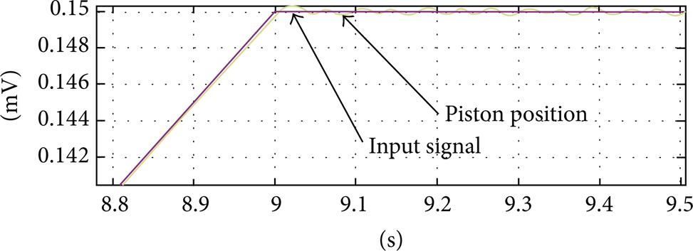
Oscilloscope traces of the PID controller signal input and piston position showing small fluctuations at the stable position.

FFT spectrum of typical fluctuations observed in hydraulic position.
Here we just provided simulation results. As this is a practical application research project and the developed control system is applied for the drill jumbos manufactured by MTI, more details about experimental data such as the actual PID control gains and graphics are business confidential and not allowed to be published publically.
6. Pose Errors
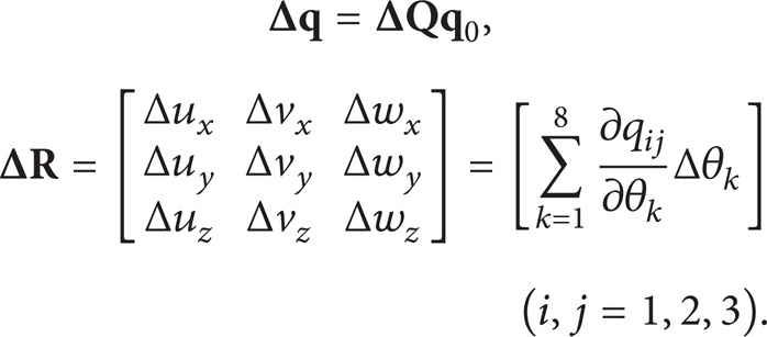
From the above control strategy, one can see that the closed-loop controllers corresponding to all joints are local and independent of each other. In other words, although every joint variable is controlled using a PID feedback controller, the whole system is not a closed-loop feedback control. Hence, it is necessary to conduct the analysis of the pose error of the end-effector, which is caused by the errors of the joint variables. From (7), the error of the transformation matrix

where
Also, the orientation error of the end-effector can be given as the angle between the actual

Suppose that the tolerance for the revolute joints is

It can be seen that the elements of
Pose errors of the end-effector.

7. Conclusions and Discussions
In order to improve the efficiency of underground mining and tunneling operations and to realize automatic drilling, more and more customers are interested in large drill jumbos with an automation system. This work focused on the development of the automation system for one such drill jumbo, which is widely used in mining and tunneling industries and built by MTI. To realize the automatic procedure, an algorithm was proposed to calculate the desired pose of the end-effector. In particular, an algorithm was proposed to solve the inverse kinematics of the drill jumbo which is actually a redundant robotic manipulator. The proposed algorithm has been demonstrated to be efficient because, for a given set of θ1 and θ5, it does not involve any numerical iteration and manipulation of matrix such as Jacobian matrix and its inverse usually needed in solving the inverse kinematics problem. Also, it is not necessary to handle the singularity problem that is often encountered in matrix manipulation. Of course, the whole calculation procedure described in Section 4 is an iterative process in terms of the choice of θ1 and θ5. However, it does not depend on the execution of an unsuccessful pose before its failure can be predicted.
When the joint variables are available, PID feedback control approaches were used to independently control the eight joint variables. Also, the simulation model in Simulink was developed and the hardware-in-the-loop simulations in a real time xPC target machine were conducted. Considering that the whole system is not a closed-loop feedback control, the analysis of the pose error of the end-effector was conducted. The results are satisfactory in the context of mining applications and the developed automation system is being applied in the drill jumbos built by MTI.
Conflict of Interests
The authors declare that there is no conflict of interests regarding the publication of this paper.
Footnotes
Acknowledgments
This work is financially supported by (1) China State Key Laboratory of Silkworm Genome Biology; (2) the Fundamental Research Funds for the Central Universities 2362014xk17; (3) Project Development Funds of Mining Technologies International Inc.