
Abstract
Acoustic channels are characterized by long multipath spreads that cause intersymbol interference. The way in which this fact influences the design of the receiver structure is considered in this paper. To satisfy performance and throughput requirements, we propose a consecutive iterative BCJR equalization scheme. To achieve a low error performance, we resort to the powerful BCJR equalization algorithms to iteratively update probabilistic information between inner decoder and outer decoder. Also, to achieve a high throughput, we divide a long packet into a group of small consecutive packets, estimate channel information of the current packets, and use it to decode the next packets. Based on an experimental channel response, we confirm that the performance is indeed improved for long packet size.
1. Introduction
It is well known that underwater channels are often hostile for underwater (UW) sensor communications, which impose three major obstacles for coherent transceivers. One is the excessive multipath delay spread in a UW channel, which usually causes the intersymbol interference (ISI). Another obstacle is the Doppler shift due to the relative motion between the source and the receiver, which causes compression or dilation on the received signals. The last one is the fast time varying phase drift due to random nature of the UW acoustic channels.
Various methods to cope with the multipath effect have been developed. A well-known method to counteract ISI is the decision feedback equalizer (DFE), which has been used in many UW sensor communication applications [1, 2]. However the use of DFE has difficulties when the multipath with a number of arrivals has equal strength or low SNR [3]. The other way to cope with ISI is to use an iterative equalizer which consists of an outer loop in addition to the inner loop BCJR decoder in the receiver. The assembly utilizes the error correcting capability of the convolutional codes to get an efficient equalizer [4, 5]. Alternatively, to cope with multipath effect, we adjust the packet length according to the channel coherence time. Due to the very short coherence time, we can only transmit small packets, which reduces the throughput. To achieve a high throughput, we divide a long packet into a group of small consecutive packets and use the estimated channel information of previous packets to compensate for the current and next packets. In this paper, we employ an iterative receiver structure with fine-tuned parameters to process experimental data from a fixed source to a fixed receiver at the data transmission rate of 1 k-symbol/s. The results indicate that the proposed algorithm works effectively well and indicate how much coding gains can be obtained as the iteration number increases.
2. Generic Transmission Model of Underwater Communication
The baseband model of the generic transmission system is shown in Figure 1. It shows that the iterative linear equalizer is a decision feedback equalizer, which deals with the outer code of the receiver. An inner code consists of convolutional codes. The information data to be transmitted are encoded by one-half rate convolutional codes with the constraint length of 7.

Baseband model of transmission system with turbo equalization.
Convolutional codes are used extensively in numerous applications in order to achieve reliable data transmission, including both wireless and underwater communication. A popular convolutional code with a constraint length of 7 and a rate of 1/2 is widely used. For example, the
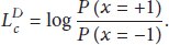
Let


The value of
2.1. General Packet Structure
The packet structure is shown in Figure 2. A packet is preceded by a linear frequency modulation beginning (LFMB) signal to indicate that the packet is about to start. After silence period, the packet starts. The packet consists of preamble (P) and payload (D) fields. The preamble of 256 symbols is used for the initial channel and Doppler estimation. The payload field contains 500 coded QPSK symbols. The packet ends with another LFM signal identified as LFME (LFM End). During transmission, to avoid interpacket interference, the packet size should be small and the gap sufficiently long. These requirements apparently reduce the throughput.

General packet structure (change the data symbol length from 1000 to 500).
Figure 3 shows the procedure of using the preamble to assist the demodulation of the data symbols. Using the preamble data, the frequency and phase offset are estimated with a Doppler frequency and phase estimation algorithm, which will be described in Section 2.2. The estimated frequency and phase offset are fed to the payload field to compensate for the Doppler frequency and phase offsets. After the whole data packets are compensated using the estimated frequency and phase offsets, the compensated data are fed to the equalizer.

Frequency and phase offset compensation.
2.2. Doppler and Phase Estimation Algorithm
A preamble of known symbols is inserted to the beginning of each packet for the carrier frequency and clock timing recovery. Among various methods, data-aided (DA) estimations are normally employed to attain a good performance with a short preamble [10].
Filtering the received waveform in a matched filter and sampling it at proper times yield


As seen in (6),


3. Proposed High Throughput Receiver Structure
To improve the system throughput, a new packet structure shown in Figure 4 is proposed. The lengths of P and

Packet structure.
This packet structure may suffer from performance degradation in the fast time varying channel. However, the performance degradation can be alleviated by a recursive frequency offset compensation procedure shown in Figure 5. In Figure 5, the 2-step demodulation procedure is illustrated: In the first step, the first data packet is demodulated using the Doppler and phase information estimated from the preamble, and in the second step, the second data packet is demodulated using the Doppler and phase information estimated from the first data packet after being demodulated. In fact, we can use this approach to divide a long packet into small consecutive packets and to demodulate the subsequent small packets using the information obtained from the previous small packets, thereby improving the system throughput in the fast time varying channel environments.
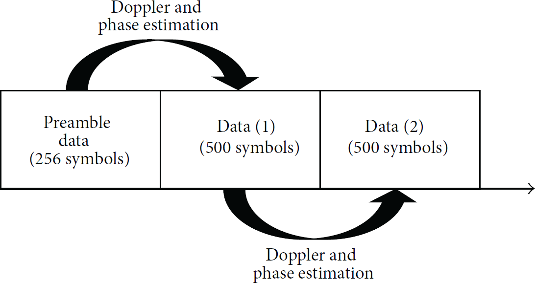
A recursive procedure of Doppler and phase compensation.
The frequency and phase offset information resulting from the preamble data is used to compensate for any frequency and phase offsets in the
The receiver structure for the proposed high throughput packet model is shown in Figure 6. As explained above, to achieve high throughput, we divide a long packet into small consecutive packets and use the estimated channel information from the previous packets to assist the demodulation of the next packets. The proposed receiver consists of buffer, reencoder, and remapper. Buffer stores received packets in order to estimate the Doppler and phase offsets for the current data packet. For example, to estimate

Proposed high throughput receiver model.
4. Experimental Results
We evaluate the performance of the proposed packet transmission model in real underwater environments. The experiment was conducted on a lake of Munkyeong city, Korea, in May 2014. The water depth was approximately 43 meters. Figure 7 depicts the lake trial.

Illustration of the lake trial.
The transmitter emits a source signal with center frequency of 16 kHz and data rate of 1 kbps. The hydrophone was at 20 m below the water surface, and the horizontal range from transmitter was 400 m. The received signal was sampled at 192 kHz. The experimentation with two types of packet structure is conducted.
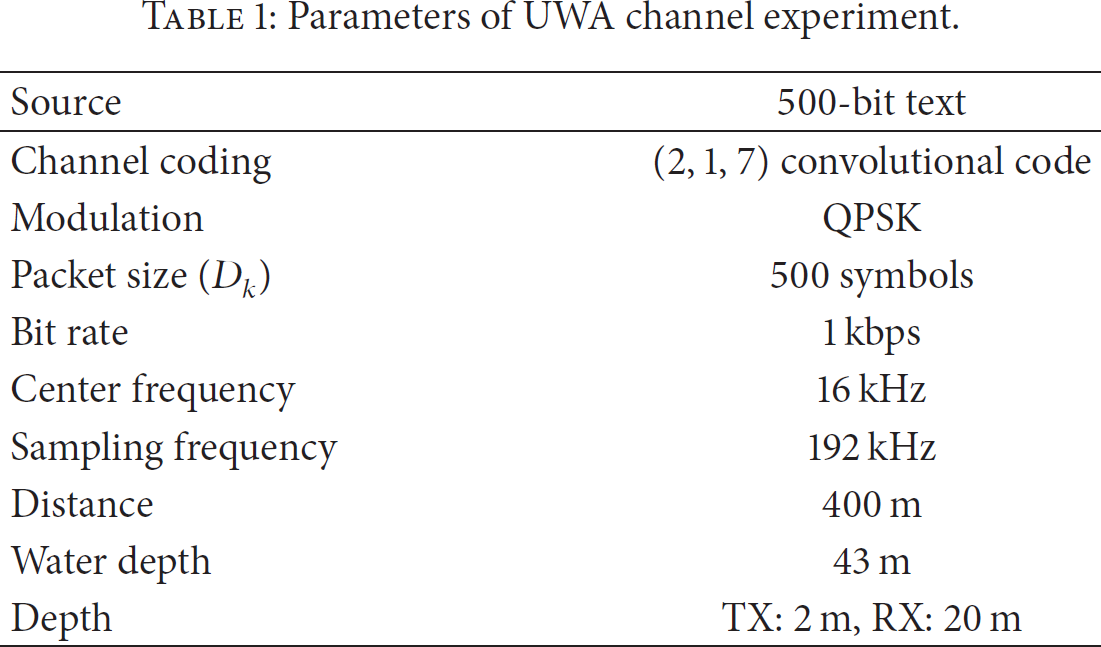
In Figure 8, the underwater channel response is shown during a 0.1-second interval. This response was measured by using an LFM signal with a bandwidth of 4 kHz. The channel gains for the secondary and third arrivals fluctuate more rapidly. This sparse channel is affected by multipath propagation by reflection from the surface and the bottom. Experiment parameters are listed in Table 1.
Parameters of UWA channel experiment.

Underwater channel response.
Figure 9 illustrates the error performance of the conventional system and the proposed system. The received symbols have a total of 1047 bit errors in the first and second data fields (

BER comparison between the conventional and the proposed methods.
5. Conclusions
Underwater acoustic channels are characterized by long multipath spreads that cause intersymbol interference in addition to Doppler shift due to the relative source-receiver motion. To improve the system performance and throughput in the presence of these major obstacles, we have proposed a consecutive iterative BCJR equalization for a long packet size. To achieve the high throughput in the fast time varying channels, we divide the long packet into small consecutive packets and use previous packets to estimate channel information needed to compensate for the subsequent packets. The error performances of four different decoding algorithms are compared based on real experimental data measured on a lake in Munkyeong city. We demonstrate that the proposed algorithm can correct all errors of received symbols, thereby confirming that the proposed algorithm is very effective for communications in the time varying underwater communication channel.
Footnotes
Conflict of Interests
The authors declare that there is no conflict of interests regarding the publication of this paper.
Acknowledgments
This work was supported by Defense Acquisition Program Administration and Agency for Defense Development under Contract UD130007DD. This research was financially supported by the Ministry of Education, Science Technology (MEST), and National research Foundation of Korea (NRF) through the Human Resource Training Project for Regional Innovation.