
Abstract
In future wireless communication systems, the capacity constrained backhaul gradually becomes bottleneck both in spectrum efficiency and energy efficiency, especially in joint processing of LTE-Advanced. This paper addresses the issue of energy aware resource allocation with limited backhaul capacity in uplink cooperative reception, where two base stations (BSs) equipped with single-antenna each serving multiple users with single-antenna via multicarrier are considered. We propose a novel energy efficient cooperative scheme based on compress-and-forward and user pairing to solve the problem in two base stations scenario. In order to maximize system throughput and increase energy efficiency under the limited backhaul capacity constraint, we formulate the joint optimization problem of user pairing, subcarrier mapping, and backhaul capacity sharing between different pairs (subcarriers). An energy efficient algorithm based on alternating optimization strategy and perfect mapping is proposed to solve this mixed integer programming problem. Simulations show that this allocation algorithm can improve the system capacity and energy efficiency significantly compared with the blind alternatives.
1. Introduction
With the increasing demand of higher transmission rate and more reliable QoS in wireless personal communications, cooperative schemes are in great need to meet the demand of users, including the cell-edge user with poor performance. To satisfy the demand of users, network operators such as China Mobile must establish more and more base stations to provide more resources for users. The increase of base stations not only fulfills the demand of users, but also leads to the increasing of energy consumption. Traditional method that reduces energy consumption considering the cooperation scheme is mainly about shut down idle base stations; however, in cooperative scheme [1], on-off control will greatly affect the system performance. So in cooperative scheme, the main consumption of the system power is the backhaul power consumption according to [2].
Traditional energy aware optimization scheme could reduce the energy consumption of base station equipment by shutting down idle service nodes, especially by utilizing the traffic tide [3, 4]. In the daytime, base stations are usually in normal load and are not capable for on-off control frequently; on the contrary, in the night time, number of users that require data traffic are far more small than that in the daytime, so there exists the chance to shut down the idle base stations according to the actual status of the data traffic. This is the most effective method to reduce energy consumption due to the architecture of the wireless network [5, 6]. In cooperative networks, energy consumption in backhaul transmission becomes critical recently. In cooperative scenario, data and channel information will be transmitted through cooperative link, such as X2 or S1 interface in LTE related systems [7, 8]. The large amount of cooperative data will cost much resource such as signal processing and transmission, which takes up about 60% of the total power consumption [9, 10]. To reduce the energy consumption in cooperative scenario, one possible way is to reduce the amount of data, which is transmitted through cooperative link [11]. The cooperative link is to reduce interferences from adjacent service nodes and perform collaborative transmission via given link in its original point of view. However, the increasing performance will bring heavy traffic load in cooperative interface [12].
To tackle this problem, various intercell interference mitigation techniques have been put forward, for example, coordinated multipoint transmission/reception (CoMP). This technique avoids or exploits interference through BSs coordination, which is implemented by information sharing via backhaul among coordinated BSs. Generally, there are two ways: (1) CB/CS: neighbor CSI is exchanged for coordinated scheduling and beam forming [13, 14]; (2) JP: data traffic is shared for joint decoding or transmission [15, 16] in uplink and downlink. Both of them inevitably bring increased demand on backhaul. The realistic backhaul capacity constraint is more serious especially when full cooperation based on data sharing is employed [17].
Uplink joint decoding means that the signals received at different BSs are jointly decoded through exchanging quantized information between cooperative BSs [18]. This scheme can exploit diversity and cooperative gain to a large extent, similarly to virtual MIMO, which takes much overhead on the capacity limited backhaul. Therefore, it is necessary to reduce the redundancy in exchanged information, improving the efficiency of backhaul utilization.
In this case, problems could be solved using distributed source coding with side information [19, 20]. Based on this concept, a new backhaul efficient approach called distributed compression is proposed in [21, 22]. These works suppose that multiple cooperative BSs compress and forward their received signals through backhaul to the central BS for joint decoding. As these compressed versions carry only necessary information for BS A, backhaul overhead is largely reduced and the joint processing gain is obtained at the same time. It shows in [23] that this compress-and-forward scheme achieves good performance even with limited backhaul capacity. However, this work is based on a single frequency network. The optimal backhaul capacity allocation in more practical multicarrier systems has not been considered yet.
Therefore, in this paper, we focus on multicarrier coordinated network constrained by limited backhaul capacity, where two single-antenna BSs are coordinated to joint decode information from their multiple single-antenna users. In order to reduce energy consumption and increase system performance, a complex optimization problem has been formulated. We formulate a joint optimization problem of user pairing, subcarrier mapping, and backhaul capacity sharing between different pairs (subcarriers). A low complexity but efficient algorithm based on alternating optimization strategy and perfect mapping is proposed to solve this mixed integer programming problem. Simulations show that this allocation algorithm can improve the system capacity significantly compared with the blind alternatives.
The structure of this paper is as follows. In Section 2, our system model and problem formulation are presented. After that, the proposed algorithm is introduced in Section 3. Finally, numerical results are presented in Section 4 before conclusions are drawn.
Notation. In the following, boldface lowercase alphabets are used to denote vectors whereas boldface uppercase alphabets denote matrices.
2. System Model and Problem Formulation
2.1. Preliminary
First, we give a brief introduction to the compress-and-forward scheme [23] in two BSs case (depicted as Figure 1). BS 1 acts as central node to execute joint decoding. BS B acts as cooperative node, forwarding its information via a unidirectional backhaul link from BS 2 to BS 1. The specific operations are as follows.
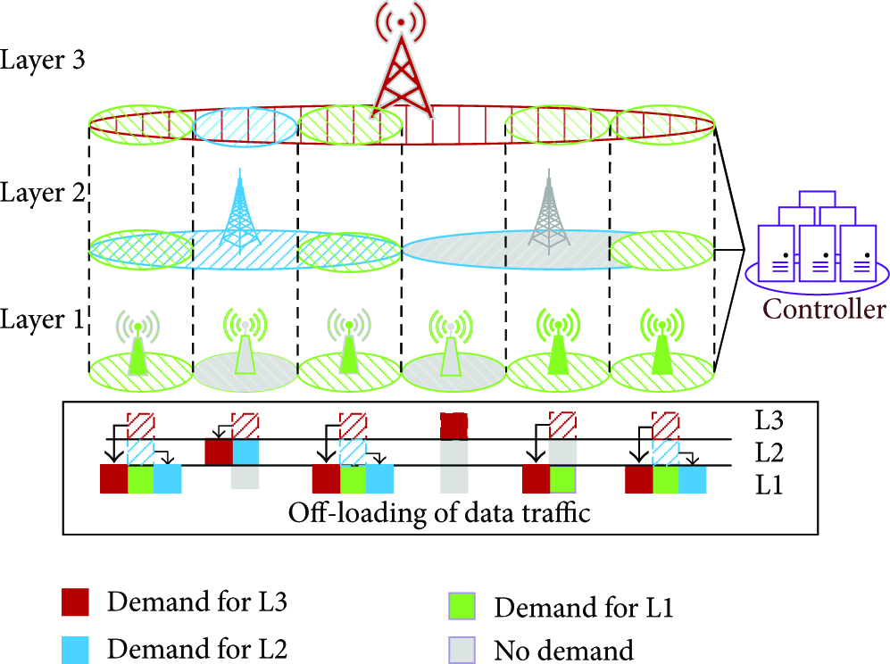
Flexible coverage architecture.
(1) BS 2 compresses and encodes its received signal, which is a mapping from a received sequence

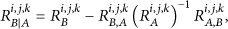
(2) BS 1 reconstructs the compressed signal with its received signal

(3) BS 1 jointly decodes users’ information from
This compression and reconstruction process has been modeled as Gaussian test channel:

2.2. System Structure Model
The “flexible coverage architecture” that consists of different types of base stations is known as heterogeneous deployment but with some markedly difference. In this architecture, the system could not only decide which and how many base station should be off according to network load but also knows which (locate the time and position of the incoming transmission) and how many base station should be in active status again if users are requiring data traffic.
First, the architecture could help decide the proper service node according to the characteristic and correlation of different data traffic in a cooperative way that means, for any given traffic data waiting to be served by network, they could always be sorted and aggregated to proper layers. In general, different layers indicate different types of base stations, and the layer with larger coverage will not only provide low speed service but also tells the position which small coverage layer should be on when some of the users located in blind zone are requiring data traffic. That means, when some of the base stations are switched off, users located at these areas will lose coverage and fail to be served in traditional architecture. In our novel architecture, these users could get access to upper layers to gain control service or low speed data transmission first and then hand over to proper active small coverage base stations.
Second, the new architecture allows the separation of signaling type and data type traffic to meet the demand of future wireless systems dynamically; that is to say, users could be served from different base stations; for example, control signaling could be served from macrobase stations and data traffic could be served from pico cells at the same time. Signaling type data traffic contains the necessary independent wireless signaling data such as paging, channel sounding, and broadcasting and some other signaling like signals, such as the heartbeat signal (used in instant message software to indicate the “active” status of users, e.g., the instant message service like MSN Messenger). These signals do not last long and consume little bandwidth/power resources that could be served separately without affecting the common communication of users. On the contrary, the data type traffic is the useful information data that include the required upper application layer information, such as online video and ftp downloading. This type of traffic could not always be served by any base stations for the QoS demand is different. For example, the high speed online meeting will require higher transmission speed that could not be served by macrobase stations. Of course there are exceptions of signaling type data traffic; if the signaling data is transmitted in conjunction with data traffic closely, it would not be separated. For instance, the pilot signal included at the head of the transmission frames is used to obtain channel information and perform channel estimation for transmission schemes (some precoding operations like beam forming [25], joint transmission, etc.); which could not be separated. Third, the new architecture allows the “absorption” operation among different layers. That means, the layers that serve high speed data traffic could also serve lower speed traffic within the coverage of high speed layers. Then, the active high speed layers could be fully utilized to save energy, compared to traditional heterogeneous networks with lean carrier [26]. This part of work has been presented and published in IEEE ICSGRC 2014 [27].
To make the description clear, we elaborate a three-layer model in Figure 1. In this figure, we illustrated the design and function of the novel architecture. The three layers connected to a central controller using X2 interface or S1 interface in our given figure (in fact, the number of layers is not fixed, depending on number of different base station types), and different layers have different coverage ability. Layer 1 (painted green) has the smallest coverage ability but a larger amount and layer 3 (painted red) could provide the largest coverage but lowest service node, and layer 2 is the medium layer (painted blue). The grey color means that the node is working in inactive mode. From bottom to top and left to right, the first “row” indicates the fact that within the coverage of layer 1, all traffic data from upper layers 2 and 3 could be absorbed to the bottom layer, because layer 1 base station could afford not only high speed traffic within its own range, but also low speed traffic from any overlapped upper layers. In “row” 2, there are rarely users with high speed demand, so the layer 1 coverage is off, and layer 2 coverage automatically takes up the service of layer 3 within the same range. In the fourth row, both layer 1 and layer 2 are off, which represent the fact that the load of the network is low (most of the users are in inactive status and only low speed signaling or data traffic is required by users, e.g., late at night), so layer 1 and layer 2 coverage with better service ability would be off to save energy. When users located in this area are requiring data service, layer 3 coverage could not afford, and layer 3 coverage could locate the nearest small coverage and tell it/them to turn into active status, which could be recognized as the cognitive function of the time and position of upcoming traffic. The fifth “row” indicates the condition that the medium layer is off according to the traffic load. If layer 1 is on, all traffic within the coverage of layer 1 will be served by this layer to reduce the overload in layer 3.
The advantages of the novel “flexible coverage architecture” could be summarized as follows.
The design and implementation of the architecture are simple, only depending on the kinds of different base stations, and connected them through X2 or S1 interface to make the coordination of different base stations available. The architecture allows the separation of data type traffic and signaling type traffic, which makes the on-off operation easier and effective (this is also the first time to say signaling and data type traffic, not the signaling and data traffic in an absolute way, considering the various types of traffic with different characteristic). The architecture allows absorption operation in the overlapped coverage, to make full use of all active base stations.
2.3. System Power Model
In Earth project [3], they raised a power model to map transmit power to dynamic power consumption. There are also some other mapping methods such as in [28, 29]
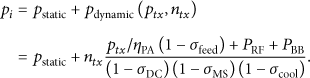
The dynamic power consumption
2.4. Signal and System Model
The system in investigation is depicted in Figure 2. It consists of two single-antenna BSs and N single-antenna users designated to each. These users are paired and mapped onto K subcarriers for transmission. For example, user 1 in BS 1 is paired with user 4 in BS 2 and mapped on the subcarrier denoted as blue line. Compress-and-forward scheme is employed, where BS 1 is central node and BS 2 is cooperative node. Backhaul capacity is

A two BSs cooperative scenario.
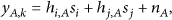
The channel model in frequency domain is listed as follows:

The compression and decompression process is similar to scalar case:

3. Problem Formulation
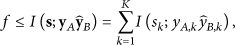
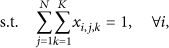
(1) The Achievable Rate. Assume that different subcarriers are perfectly orthogonal to each other; the achievable sum rates should satisfy
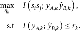
(2) The Backhaul Overhead. Consider


Obviously, this rate vector can also be viewed as backhaul capacity allocation vector. And we will use these two terms without distinction in the rest of the paper.
(3) The Backhaul Power Consumption. Consider
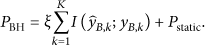
In this equation,
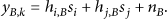
(4) Joint Optimization Problem. The objective of our work is maximizing system throughput. Therefore, we formulate the joint optimization problem by combining backhaul capacity allocation with user pairing and subcarrier mapping. We introduce a set of binary variables
Substituting (9) into (8) and combining variable


4. Resource Allocation Algorithm
As (12)~(14) are a nonlinear mixed integer programming, it is difficult for us to tackle directly. According to [30], we can maximize some variables first and then the remaining variables. Therefore, to explore the internal features of our problem, we observe some variables taking others fixed.
4.1. Optimize Compression Noise Φ
For the fixed assignment variables


As
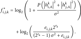
This equation indicates that the achievable pair rate can be decomposed into two parts. The first one is attributed to the additional information offered by the backhaul rate allocated to subcarrier k.
It can be easily verified that
4.2. Optimizing Backhaul Capacity Allocation Vector r
For a fixed user pairing and subcarrier mapping
4.3. Optimizing User Pairing and Subcarrier Mapping x
Given

It is a standard three-dimensional assignment problem and is NP hard in most cases. The variable x is a mapping function between two base stations; in the following description, we will first define the mapping method. If x is defined, it will become standard assignment problem. In order to deal with it practically, we developed a suboptimal method which also has pretty performance. This method is reducing this three-dimensional assignment problem into two-dimensional assignment problem.
Similar to (29), the whole sum rate achieved by all subcarriers is composed of two terms: the first one is the sum rate when only
Therefore, for each timeslot, we can first map scheduled K users in cell 1 onto the K subcarriers such that achievable sum rate of these users is maximized, which is also consistent with no cooperation scenario. The procedure can be easily achieved by selecting the best user for each subcarrier. Here, we use a mapping function

Then we pair users in cell A with users in cell B by using the function
4.4. Proposed Algorithm
Through discussions in

In a summary, for fixed
Therefore, we developed an alternating optimization algorithm by solving convex problem and linear programming alternately. According to [24], this algorithm converges to the optimal solution of problem
(1) Mapping users in cell A onto K subcarriers using α (2) Initialize (3) (4) (5) Get (6) Compute (7) Compute (8) Get (9) Compute objective function (10)
5. Numerical Results
5.1. Simulation Assumption and Parameters
We evaluate the performance of our algorithm on the MALAB platform. The distance between two BSs is 500 m. The radius of each cell is 300 m. During each timeslot, there are 8 users transmitting simultaneously via 8 subcarriers in each cell and their positions are randomly generated. Wireless channel taken in our simulation is multipath Rayleigh fading with pass loss exponent
As the benchmarks, the performance of random pairing with equal backhaul (RPEB) capacity allocation and random pairing with random backhaul (RPRB) capacity allocation schemes is also presented. Specifically, both RPEB and RPRB let α be the same as our proposed algorithm and
5.2. Result Analysis
In Figure 3, we evaluate the result in two BSs scenario for theoretical analysis. The x-label indicates that the system received SINR and the y-label means the spectrum efficiency. The red curve represents the performance that the system does not consider backhaul limitation, and the green one is our proposed method and the blue one is the reference method given in [31].

System SINR versus spectrum efficiency.
In this figure, it is obvious that the spectrum efficiency is the best among all the three methods. In our proposed method, when the received SINR is below 14 dB, the proposed method is better than the reference method, and it is because the optimal multilevel optimization makes full utilization of the backhaul capacity and the reference method do not obtain the gain in group and compress the transmission signal, and the reference method performs poorly due to the poor channel environment and will require more cooperative bandwidth to perform cooperation. When the received SINR gradually increases, the reference method receives better performance in spectrum efficiency because the better channel condition will greatly reduce the information that transmitted in system backhaul, which lead to the effect that there are less information to be transmitted in the capacity constraint backhaul.
In Figure 4, we evaluate the power consumption of the system backhaul. The power model of the backhaul is defined in (10). Without backhaul limit, the backhaul power consumption does not change according to the cooperative scheme. The reference method could partly reduce energy consumption due to the consideration of the BH capacity limit. In our proposed method, we are trying to make full utilization of the system backhaul capacity and reduce the amount of data transmitted in the backhaul link, which will lead to the effect that the energy consumption of the backhaul could be reduced.

Backhaul capacity versus energy consumption.
So in our proposed method, when BH capacity is low, we could gain about 30% of the total energy savings compared to the reference method. When the capacity increases, the energy consumption that adopt our proposed method would not cause the increasing of energy consumption when BH capacity is larger than 6 bit per channel use, so we could gain about 15% of the energy savings compared to the reference method.
Figure 5 compares the average sum-rate achieved by different schemes. We can get the following observations.
Our proposed algorithm outperforms two benchmarks by a significant margin. As the backhaul capacity grows; this margin also grows. This is because the proposed algorithm has more and more freedom to allocate backhaul capacity. Until the backhaul capacity is sufficient, this margin stays stable. It verifies that optimal backhaul capacity allocation is necessary to obtain better system performance. These three curves have a common tendency. As backhaul capacity grows, sum rate at first increases approximately linearly, and then it rises slowly, and finally, it enters into a stable stage. This is because, at this low backhaul capacity region, system capacity is limited by backhaul capacity rather than additional information BS B can offer. In other words, the upper cut set bound is dominant. However, at the high backhaul capacity region (larger than 60 bpcu as depicted in figure), the additional information offered by BS B becomes the limited factor. That is the upper multiple access channel bound is dominant. At this region, sum rate is saturated. In addition, when backhaul capacity equals 0; three curves converge to the same point. This is because three schemes have the same initialization at this point. In other words α is the same.

Average sum-rate versus backhaul capacity.
6. Conclusion
In this paper, we have studied the uplink optimal resource allocation with limited backhaul capacity in multicarrier coordinated network. A novel efficient algorithm based on alternating optimization strategy has been put forward to solve the joint optimization problem of user pairing, subcarrier mapping, and backhaul resource allocation. Simulation results show that the proposed algorithm can significantly improve system performance compared with blind schemes. They also illustrate that when CSI from neighbor cell is available, channel aware backhaul allocation outperforms unaware schemes (random or equal strategy). However, when CSI from neighbor cell is unavailable, equal backhaul resource allocation is fairer.
Footnotes
Conflict of Interests
The authors declare that there is no conflict of interests regarding the publication of this paper.
Acknowledgments
This work is funded by China's 973 Project under Grant of 2012CB316002 and China's 863 Project under Grant of 2013AA013603, 2012AA011402, Qualcomm Innovation Fellowship, whose funding support is gratefully acknowledgment. The author would also like to thank all the reviewers for their suggestions which help improve the work a lot. The authors would also like to thank Professor Hongyi Yu, for his kind and wise suggestion on this research.