
Abstract
With the rapid development of underwater acoustic modem technology, underwater acoustic sensor networks (UWASNs) have more applications in long-term monitoring of the deployment area. In the underwater environment, the sensors are costly with limited energy. And acoustic communication medium poses new challenges, including high path loss, low bandwidth, and high energy consumption. Therefore, designing transmission mechanism to decrease energy consumption and to optimize the lifetime of UWASN becomes a significant task. This paper proposes a balance transmission mechanism, and divides the data transmission process into two phases. In the routing set-up phase, an efficient routing algorithm based on the optimum transmission distance is present to optimize the energy consumption of the UWASN. And then, a data balance transmission algorithm is introduced in the stable data transmission phase. The algorithm determines one-hop or multihop data transmission of the node to underwater sink according to the current energy level of adjacent nodes. Furthermore, detailed theoretical analysis evaluates the optimum energy levels in the UWASNs with different scales. The simulation results prove the efficiency of the BTM.
1. Introduction
Recent advances in acoustic communication and wireless sensor networks have motivated the development of underwater acoustic sensor networks (UWASNs), which consist of underwater acoustic sensor nodes. Compared with the traditional approach to ocean-bottom or ocean-column monitoring, UWASNs can be used to collect real-time information from a given area and increase the efficiency of many applications, such as real-time warship monitoring, oceanographic data collection, environmental monitoring, offshore exploration, maritime rescue, disaster prevention, and autonomous underwater vehicles (AUVs) management [1].
Due to the high attenuation of seawater, wireless communications in underwater environment are usually based on acoustic links. Underwater acoustic communication channels are significantly different from radio channels in the air; many energy-efficient schemes developed for terrestrial wireless sensor networks perform poorly in the underwater environment [2]. The specific characteristics of acoustic channels include high energy consumption, limited available bandwidth, limited battery power, low transmission speed, severely attenuated channel, long propagation delay, and high bit error rates. The new protocols are expected to be designed in terms of the unique character in underwater acoustic channels [3].
Since it is difficult to accomplish battery replacement and the sensor nodes in underwater scenarios are expensive, it is extremely important to achieve lifetime prolonging of UWASNs. When some sensor nodes run out of their energy and die early, the remaining nodes cannot cover the sensing area efficiently, and UWASN cannot receive enough data so that the network will collapse; in the meantime, some sensors still keep a lot of energy and the costly underwater acoustic sensor nodes will be wasted. Consequently, the main problem of lifetime of UWASNs is that the system will collapse for a few nodes dying out even if there may still be significant amount of energy in the other nodes. This problem can be described as the unbalance of energy consumption among sensors nodes. According to the energy consumption model of underwater acoustic sensor, the energy consumption is related to the transmission distance, path loss, data load, and so forth [4]. The transmission modes of the sensor nodes include direct transmission and multihop transmission in UWASN. In the direct transmission mode, sensor nodes directly transmit the data to the sink by single hop. Thus, the farthest sensors away from the sink run out of their energy earlier because of longer transmission distance. Sensor nodes transmit the data to the sink by multihop forwarding transmission in the multihop transmission mode, which is usually employed in the underwater acoustic communication because of the short transmission distance with less energy consumption [2]. However, in the multihop transmission, the sensor nodes closer to sink tend to run out of their energy earlier because of more data load while they pass all the data collected from the sensor nodes to the sink [5]. As a result, the unbalance of energy consumption among sensor nodes is an important problem existing in both transmission modes; that is, when some sensor nodes run out of their energy and die early, UWASN will collapse; in the meantime, the other sensor nodes still keep a lot of energy and will be wasted. To avoid some sensor nodes dying earlier and the huge energy being wasted because of the sensors unbalancing employment in the UWASN, the switching of communication modes is necessary between direct transmission and multihop communications.
This paper elaborates balance transmission mechanism (BTM). Necessary acoustic direct transmission is adopted when excessive local energy consumption occurs in multihop transmission. BTM decides the data transmission mode of one-hop or multihop to the sink based on the current energy level (EL) of underwater sensor nodes (uw-sensor nodes). At first BTM needs to build the fundamental route for packet transmission. This study gives the efficient route algorithm in the route set-up phase. In the previous research, the optimum transmission distance was obtained by minimizing the energy consumption in the whole process of each uw-sensor node sending packets to the uw-sink in the multihop communication. This paper selects the relay node where the point-point distance between the sending node and the relay node is closest to the optimum transmission distance and establishes the trees-route in the efficient route algorithm. All nodes transmit the packets by multihop forwarding next hop towards the underwater sink (uw-sink) along the tree-route. When the load in a node is so heavy that the EL of the node decreases to certain degree, it informs its predecessor nodes obtained in the routing tree to transmit the packet directly to the uw-sink. And then, the data will be transmitted by multihop forwarding transmission again when this predecessor nodes EL decreases to some degree. During data transmission, a node can decide whether to forward data to next hop towards the uw-sink, or to send data directly to the uw-sink by comparing its EL to its adjacent neighbors. Furthermore, through theoretical analysis, we get the optimum number of ELs classification in both the small scale UWASN and the large scale one and use it in the BTM. The UWASNs lifetime can be further prolonged.
The contributions of this paper are as follows. (1) The data balance transmission algorithm with EL is proposed, which prolongs the lifetime of the whole UWASN by solving the unbalance of energy consumption among sensors nodes. (2) The optimum energy levels (OELs) are evaluated from theoretical analysis in both the small scale UWASN and the large scale one.
The subsequence of this paper is organized as following. Related works are discussed in Section 2. Section 3 illustrates the network model and energy consumption model. The design of BTM is described in detail in Section 4. Simulations are presented in Section 5. Conclusions are given in Section 6.
2. Related Work
Because underwater acoustic communication channels are significantly different from radio channels in the air, many energy-efficient transmission schemes developed for terrestrial wireless sensor networks perform poorly in the underwater environment. In the underwater environment, some factors increase the designing cost of the sensors, such as waterproof, corrosion protection, and more difficult charging. And underwater acoustic wave communication poses new challenges, including high path loss, low bandwidth, and high energy consumption, Consequently, the sensors and the energy become more significant resources in the underwater environment, and it also introduces difficulties in designing transmission mechanism to use the sensors energy efficiently and prolong the network lifetime [6].
Tan et al. [7] proposed a protocol based on hop-by-hop hybrid acknowledgment scheme which was for a multihop UWASN. In the protocol, data packets forwarded by downstream nodes could work as implicit ACKs for previous transmitted data packets. Ayaz and Abdullah [8] proposed a dynamic addressing based hop-by-hop routing protocol to provide scalable and time-efficient routing for UWSN. The routing protocol did not require any dimensional location information or any extra specialized hardware compared with many other routing protocols in the same area. Vector-based forwarding [9] was a geographic approach, which allowed the nodes to weigh the benefit to forward packets and reduce energy consumption by discarding low benefit packets. Therefore, over a multihop path, only the nodes that were located within a pipe of given width between the source and the destination were considered for relaying. In the areas with low density of nodes this approach may not find the path close to the routing vector. Similarly, Jornet et al. proposed focused-beam routing [10] protocol that was suitable for networks containing both static and mobile nodes. The objective was to determine which nodes are candidates for relaying. Candidate nodes were those that lie within a cone of angle emanating from the transmitter towards the final destination. Those nodes outside the cone would not respond. MTE [11] was a classical representation of energy-efficient multihop transmission, in which each sensor node always forwarded the data packets to its neighboring node towards the sink until the data packets reached the destination. The problem of multihop routing still exists as it is based on multihop architecture, where nodes near the sinks drain more energy because they are used more frequently.
Pompili et al. [12] introduced two distributed routing algorithms for delay-insensitive and delay-sensitive applications, respectively; they aimed at minimizing the energy consumption, taking the varying condition of the underwater channel and the different application requirements into account. A theoretical argument supporting geographic routing was discussed [13] based on simple propagation and energy consumption models for underwater networks. The study showed that an optimal number of hops along a path exist and showed that increasing the number of hops by choosing closer relays is preferred with respect to keeping the route shorter. Ponnavaikkoy et al. [14] studied the energy optimization problem and delay constraints. The authors [15] developed a relay selection criterion, called cooperative best relay assessment for underwater cooperative acoustic networks, to minimize the one-way packet transmission time. The criterion took into account both the spectral efficiency and the underwater long propagation delay to improve the overall throughput performance of the network with energy constraint. A novel layered multipath power control scheme [16] took noise attenuation in deep water areas into account and proved that its optimization problem was NP complete. The authors solved the key problems including establishment of the energy-efficient tree and management of energy distribution and further developed a heuristic algorithm to achieve the feasible solution of the optimization problem. An ultrasonic frog calling algorithm [17] was present aiming to achieve energy-efficient routing under harsh underwater conditions of UWASNs. The process of selecting relay nodes to forward the data packet was similar to that of calling behavior of ultrasonic frog for mating. Different sensor nodes adopted different transmission radius and the values can be tuned dynamically according to their residual energy. The sensor nodes that owned less energy or were located in worse places chose sleep mode for the purpose of saving energy. Wahid et al. [18] proposed an energy-efficient routing protocol based on physical distance and residual energy. The protocol also took into account the residual energy of the sensor nodes in order to extend the network lifetime. It might often make the problem worse in terms of the characteristics of node mobility in UWASNs.
This paper analyzes the characteristic of energy consumption in data transmission and receiving. The optimal transmission range of acoustic communication can be decided on such analysis. An efficient route algorithm is proposed considering the factor of the optimal transmission range to decrease the energy consumption. And then balance transmission method based on the EL is present. The one-hop transmission and multihop transmission are decided by the current EL of adjacent nodes. The OELs are evaluated through theoretical analysis in terms of different scale networks. Through this mechanism, the lifetime of the whole UWASN can be prolonged.
3. Network Model, Assumptions, and Energy Consumption Model
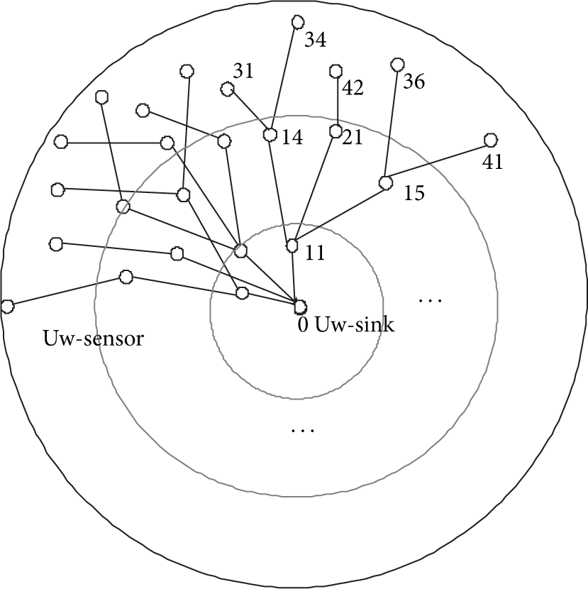
3.1. Network Model and Assumptions
The architecture of UWASNs consists of sensor nodes, AUVs, and uw-sinks, which are connected by acoustic communications. Several communication architectures of UWASNs are introduced, including two-dimensional and three-dimensional underwater networks [6]. AUVs are usually employed to gather data directly from the underwater sensor by direct transmission, which can use optical or acoustic communication [19, 20]. Nevertheless, AUVs are more costly. The reference architecture for two-dimensional underwater networks is shown in Figure 1. A group of sensor nodes are anchored to the bottom of the ocean with deep ocean anchors. Uw-sensor nodes are interconnected to one or more uw-sinks by means of wireless acoustic links. Sensors can be connected to uw-sinks via direct transmission links or through multihop transmission paths. Uw-sinks, as shown in Figure 1, are network devices in charge of relaying data from the ocean-bottom network to a surface station. The typical application of UWASNs is the monitoring of a remote environment. This paper only studies the local area with uw-sensors and uw-sink. The uw-sink is responsible for collecting data from sensor nodes. Once the uw-sink has all the data from the nodes, it transmits the data to the surface station by acoustic communication.

Network model.
For the simplification, we consider a sensor network consisting of M sensor nodes, uniformly deployed over a vast field to continuously monitor the environment, and an uw-sink, away from the nodes with a constant power supply, through which the end user can access data from the UWASN. Some reasonable assumptions are made about the sensor nodes.
Uw-sink is stationary after deployment and sensor nodes move slowly and rarely move.
All sensor nodes are homogeneous and have the same capabilities.
All sensor nodes can adjust the amount of transmit power with the transmission distance. Energy sensor node has its maximum transmission power; that is to say, it has its maximum transmission range. The sink is within the maximum transmission range of all sensor nodes; that is, all sensor nodes can transmit data with enough transmission power to reach the uw-sink. Each node has the computational power to support different MAC protocols and perform signal processing functions.
Each sensor node is location aware by some existing positioning methods. The positioning methods belong to another research area, which are not involved in this study. The uw-sink has strong computation power.
Each sensor node senses and generates data evenly in each round.
To avoid interference, CDMA technology can be used to achieve multiple simultaneous wireless transmissions [21].
These assumptions are reasonable due to technological advances in acoustic communication hardware and low-power computing.
3.2. Energy Consumption Model
To quantify the energy consumption of the UWASNs, we adopt the energy dissipation model based on underwater acoustic communication principle. To transmit a data packet from one node to another over a transmission distance x, each node needs to transmit at a power level

where k is the energy spreading factor (1 for cylindrical, 1.5 for practical, and 2 for spherical spreading) and

is a frequency-dependent term obtained from the absorption coefficient. The absorption coefficient for the frequency range of interest is calculated according to Thorp's expression [4] as
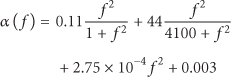
in dB/km for f in kHz.
To transmit a l-bit packet over a transmission distance x, the transmitter expends
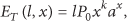
and to receive this packet, the receiver expends

where
4. Balance Transmission Mechanism
The BTM includes the route set-up phase and the stable data transmission phase. A route set-up phase is executed when the UWASN begins to work and then goes to a stable data transmission phase when data are transferred from the sensor nodes to the uw-sink. BTM presents an energy-efficient routing algorithm based on the optimum transmission distance [22] in the route set-up phase and a data transmission algorithm based on energy level in the stable data transmission phase to balance network energy consumption.
4.1. Efficient Routing Algorithm Based on Optimum Transmission Range (ERA)
Obviously, if the energy consumption in the whole process of each uw-sensor node sending packets to the uw-sink is minimized, the energy consumption of the network will be minimized. The study minimized the total energy consumed in the network and obtained the optimum transmission distance [22] in the multihop communication. In order to optimize the energy consumption, this paper proposes the ERA to establish the route in the route set-up phase.
Definition 1.
Let
The goal of ERA is to design an algorithm that select sensor nodes as more as possible near the position which is
At the route set-up phase, the detailed steps of the ERA algorithm are as follows.
The sensor node,
Select the node with the minimal
Repeat (1) and (2), until the uw-sink is within the optimum transmission distance of the sensor node sending a query packet. When the uw-sink is within the optimum transmission distance of the sensor node, the sensor node can transmit the data to the sink without relaying.
Obviously, if all the nodes repeat (1), (2), and (3), a trees-route will be set up.
An example of the neighbor node table.

Figure 2 shows the route result containing some trees at the route set-up phase.
Trees-route at the route set-up phase.
Note, once the route is set up, the data can be transmitted in the stable data transmission phase. Because the uw-sensor nodes are mobile in the real case, the route set-up phase will be operated again when the uw-sensor nodes move far away from their origin position so as not to find relay. Therefore, our algorithm is suitable for the case that the move of the uw-sensor nodes is not frequent. Otherwise, the route set-up phase must be executed constantly, which induces more energy consumption.
4.2. Data Balance Transmission Algorithm (DBT)
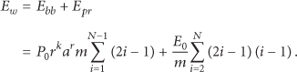
By a route set-up phase, a set of trees-route is obtained. Because the forwarding data is not aggregated in this paper; therefore the nodes close to the uw-sink die out much faster than those far away from the uw-sink. In order to balance the energy consumption, we introduce an EL; that is, we divide the node's initial energy into m equal parts and the EL of a node is
Initially, every node forwards the packet to its successor towards the uw-sink by MT mode, and their ELs is m. Some rounds later, the node which is closest to the uw-sink will dissipate more energy because of more traffic load, so its energy drops into the next energy level, that is,
Obviously, the magnitude of the EL affects the energy dissipated in the network. For all sensor nodes, if their initial numbers of the EL are 1, their transmission mode becomes multihop transmission. If the initial EL of each uw-sensor is very large, the transmission mode is similar to the direct transmission. Therefore, an optimal EL will be found in the following section.
4.3. Analysis of Optimum Energy Level (OEL)
When some sensor nodes run out of their energy, the network might collapse because it is not able to collect and to transmit data efficiently, while other sensor nodes still have much remaining energy, which causes energy waste. In order to balance energy consumption, in some cases, it is an ideal case that all the nodes in the network run out of their energy at the same time. Therefore, this section analyzes the wasted energy, minimizes it, and studies the OEL. We can virtually divide the network disk section into n ring sections or slices; the radius of slice is the optimum transmission distance.
Definition 2.
Starting from the center of the disk, where the uw-sink is located, we define the set of slices. We denote the first slice containing the uw-sink by Slice 1, which has a radius r, and use Slice
The area of Slice i is
Definition 3.
Select one sensor node in Slice 1 as one root node, a tree of the trees-route can be obtained starting from Slice 1. Let the tree be single tree. As a result, the trees-route can be composed of many single trees.
From Figure 2, the trees-route consists of many single trees whose root node is one node near the uw-sink.
Lemma 4.
The average number of uw-sensors in one single tree is
Proof.
If the uw-sensors density is ρ, the number of sensors in the Slice i is

To make it simple, we assume an ideal single tree; that is, the number of nodes in each layer of the tree is the average number of nodes of all trees in each layer, and all nodes of each layer in this single tree are in one slice; because of RTB algorithm in Section 3, the relay is selected near the optimum transmission distance. Furthermore, the number of root nodes in the single tree is 1 in Slice 1, and the average sensors number of one tree in the Slice i is
Definition 5.
Let m be the energy level and let
Definition 6.
Let the direct transmission energy consumption of one packet for the uw-sensor node farthest from the uw-sink be
Definition 7.
Let the wasted energy be
The wasted energy includes remaining energy of all uw-sensors when the networks collapse and all energy used to broadcast backwards ELNP. We can minimize the wasted energy
We discuss two cases considering the size of UWSAN. (1) We assume
Case I. We assume

When the network collapses, the maximum energy consumption of all nodes for broadcasting backwards the ELNP is

where
Definition 8.
Let
Lemma 9.
If
Proof.
We assume that each node generates a l-bit packet in each round and there are a node A in Slice i and one node B of its predecessor nodes in Slice
As a result, when the node closest to the uw-sink runs out of its energy and its remaining energy is 0, the maximal remaining energy of other uw-sensors will be obtained.
Definition 10.
We can determine the maximum remaining energy of one node in Slice i as

Then, the maximum wasted energy dissipated in this scheme is
Theorem 11.
If

Proof.
From (10), we let the derivative of

we minimize
We can see that the OEL is decided by the initial energy
In Table 2, the OELs are given with different network radius R, the transmitting power
Optimal values of m with different power and network radius R where

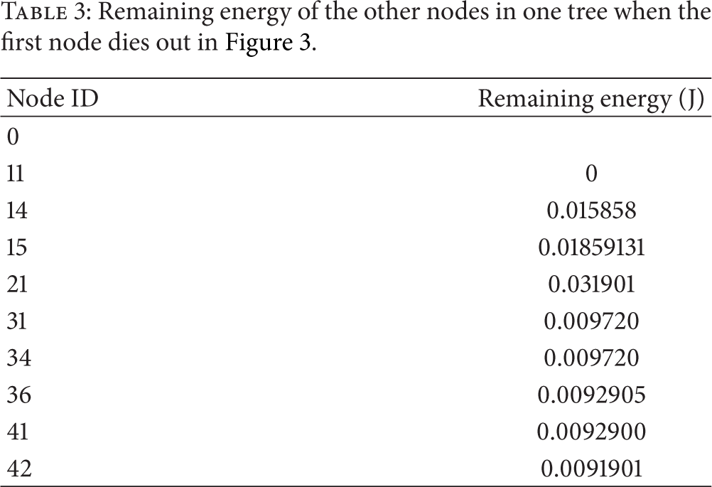
Figure 3 shows that the network lifetime of UWASN is longest when the EL is varying near the OEL where network radius = 1 km. In Table 3, we can observe the remaining energy of the other nodes when the first node dies out in one tree-route (see Figure 2).
Remaining energy of the other nodes in one tree when the first node dies out in Figure 3.
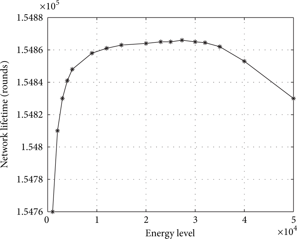
Network lifetime of UWASN versus EL.
Case II. Then, we assume
Because the maximum energy consumption of transmitting a packet is the direct transmission energy consumption of the uw-sensor node farthest from the uw-sink, the energy consumption of transmitting a packet is not more than
Definition 12.
Let the maximum energy consumption of transmitting a packet in terms of each uw-sensor node for the large scale UWASNs,

The direct transmission energy of a packet for the node farthest from the uw-sink is large so that it runs out of its energy quickly.
Lemma 13.
The times of broadcasting backward the ELNP for each uw-sensor is not more than
Proof.
From Definitions 6 and 12, we can know that if the energy consumption of the uw-sensor nodes farthest from the uw-sink for the multihop forwarding is not considered, their energy will run out via
When the network collapses, the maximum energy consumption of all nodes for broadcasting backwards the ELNP is

where
Lemma 14.
When the network collapses, the EL difference of the nodes in two successive slices is not more than n.
Proof.
We assume that there are a node A in Slice i and a node B of its predecessor nodes in Slice
Definition 15.
We can determine the maximum remaining energy of one node in Slice i as

Theorem 16.
If

Proof.
The maximum wasted energy dissipated in this scheme is

From (14), (15), and (17), we let the derivative of
From (3) and (16), we can see that the OEL for large UWSNs is also decided by the initial energy
From (13) and (16), we can obtain

Equation (18) can be simplified to

Because N can be decided by the network radius R and the transmission distance r, we can obtain the relationship between the network size and the transmission distance when
The relationship between f and the transmission distance is given in [1]. In Table 4, the transmission distance r, the network radius R, and ELs are given according to (13) and (16) with different r, where
Optimum values with different r.

5. Simulations
We made some simulations and employed the methods in a lab experiment system. The performance evaluation is done using the data from the experiment and MatLab simulator. In the simulations, the sensor nodes are uniformly distributed in a disk area, the uw-sink is in the center of the disk. The disk radius is R. The initial energy of each node is 3000 J, and in each round every sensor node generates a 200-bit packet that will be propagated to the uw-sink ultimately. In the simulation, network lifetime is denoted by identical unit, rounds. Network lifetime is defined as the time when the first node is depleted of its battery power. In simulations, we compare the performance for direct transmission by one-hop communication, MTE (minimum transmission energy algorithm) [11] by multihop communication, and BTM in both the small scale UWASN and the large scale one. MTE is a classical and known multihop method, so this study used that as the communication protocol in the multihop transmission for comparing in the simulation.
5.1. Small Scale UWASN
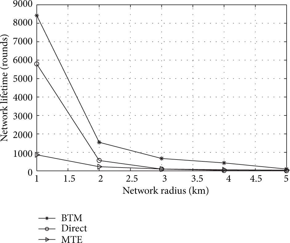
The simulation employs 80 nodes distributed uniformly in the small scale UWASN. We show the network lifetime and energy consumption with different R in Figures 4 and 5. We can see the network lifetime in BTM is longest in Figure 4. Network lifetime is defined as the time when the first node is depleted of its battery power. The network lifetime of the direct transmission is longer than that of MTE, because the network size is small so that the transmission energy consumption is not too large in the direct transmission, and the receiving energy consumption is contrastively more in MTE. This is obviously observed from Figure 5. Furthermore, we also obtain other simulation results under different sensor densities, whereas the node densities do not have too distinct impact on the current. Therefore, the simulation is enough to demonstrate the validity of BTM, in which the network lifetime can be prolonged and the energy can be saved better, which is extremely critical for UWASNs. Note that when network radius is small enough, the network lifetime and the energy consumption in BTM are nearly equal to that of direct transmission.
Network lifetime varies from different network radius R when the network is small.

Energy consumption varies from different network radius R when the network is small.
Figure 6 shows the proportion of nodes that remain alive over the simulation time. While the first node dies out, the operating time in BTM is longer than other schemes. MTE is the worst. The reason is that the more hops generate more loads on the nodes closer to the uw-sink. With more and more nodes running out of their energy, our scheme is still better, whereas when the proportion of nodes still alive is small enough, direct transmission is better than others. This is because BTM prefers energy balance to the ending time of the last nodes. The nodes closest to the uw-sink have so short distance so that the energy spent in direct transmission is very small; therefore, the ending time of those nodes is longer. Note the network maybe already collapses in that event.

Proportion of nodes that remain alive over the simulation time where the network radius = 1 km.
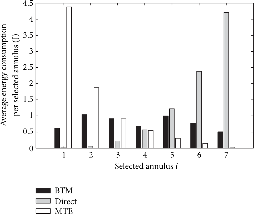
To evaluate the effectiveness of energy balancing in BTM under real network scenarios, we compare the average energy consumption per selected annulus for different network settings in the 2500th round. Here, the selected annulus is a specified area in simulations, which is not the slice specified in this paper. For achieving fair simulations, the selected annulus width is given as 0.2 km. In Figure 7, compared to the other schemes, the average energy consumption per selected annulus is best balanced in this paper. The critical maximum energy consumption in MTE is larger than that in the direct transmission because of the small network size. That is to say, the average spent energy of the selected annulus closest to the UW-sink is the largest in MTE and the average spent energy of the selected annulus farthest from the UW-sink is the largest in direct transmission, which is in agreement with the above simulations. As a result, BTM improves the network lifetime.

Average energy consumption per selected annulus in the 2500th round where the network radius = 1 km and selected annulus width = 0.2 km.
For further describing the balance character of BTM, we analyze the average remaining energy per sensor node in BTM under different rounds. The results satisfy us and verify the efficient balance of BTM. Figure 8 shows the average remaining energy per sensor node under different rounds in BTM. All remaining energy has no apparent difference in the same round. The results prove that BTM can indeed balance the energy consumption of each sensor node, because Figure 7 compares the simulation results in the random round to verify that BTM is better than the direct transmission and MTE. Of course, simulations show that the direct transmission and MTE cannot balance energy consumption, and they have their own obvious energy consumption distribution as we know. To avoid being complex and unclear, we do not depict the results of the direct transmission and MTE in Figure 8.

Average remaining energy per node for different rounds where the network radius = 1 km.
5.2. Large Scale UWASN
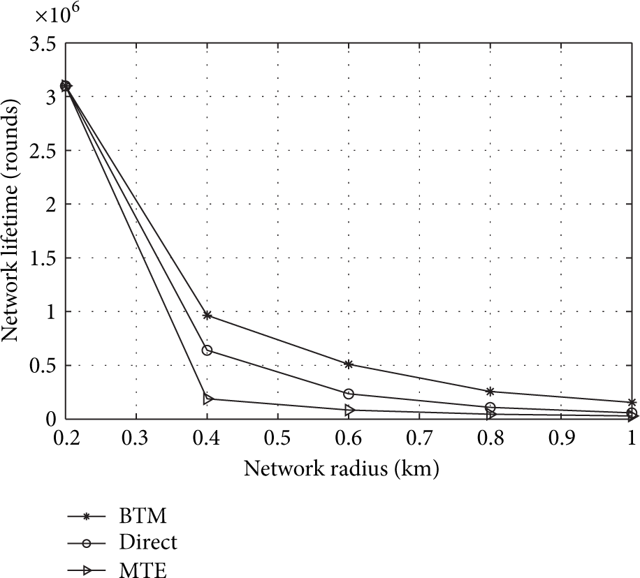
Figure 9 shows the network lifetime with different R in the large scale UWASN. We can see the network lifetime in BTM is longer. The network lifetime of the direct transmission is longer than that of MTE at the earlier time, because the smaller the network radius is, the less the transmission energy consumption is in the direct transmission, and the receiving energy consumption is contrastively more in MTE. With the network radius becoming larger, MTE is not worse than the direct transmission because of the increasing of the transmission energy in the direct transmission. Therefore, the simulation demonstrates the validity of BTM, in which the network lifetime can be prolonged, which is extremely critical for UWASNs.
Network lifetime varies from different network radius R where the nodes density is 100 nodes/km2.
Figure 10 shows the proportion of nodes that remain alive over the simulation time where the network radius

Proportion of nodes that remain alive over the simulation time.
Figure 11 compares the average energy consumption per selected annulus for different network settings in 2000th round. The average energy consumption per selected annulus is best balanced in BTM.
Average energy consumption per selected annulus where
Considering different rounds, we simulate the average remaining energy per sensor node of BTM in Figure 12, where

Average remaining energy per node for different rounds where
6. Conclusions
Because of severe energy constraints of the nodes, it is important to design protocols for UWASNs with long lifetime. This paper described the efficient routing algorithm in the route set-up phase. The routing algorithm selects relay near the optimum transmission. Then the energy level based data balance transmission algorithm was used to balance energy consumed. The uw-sensor nodes decided their transmission mode by the current EL of successor nodes. The optimal classification number of EL has been evaluated through theoretical analysis to balance the energy consumption better. Through the balance transmission mechanism, the lifetime of the whole UWASNs can be prolonged. The research model in this paper is two-dimensional UWASNs model. It can also be employed in three-dimensional UWASNs, as is not discussed repeatedly in this paper.
Footnotes
Conflict of Interests
The authors declare that there is no conflict of interests regarding the publication of this paper.
Acknowledgments
This work was financially supported by the National Natural Science Foundation (61202403) and National Scholarship Fund.