
Abstract
In underground sensor networks, electronic magnetic waves undergo severe fading due to the challenging environment. Magnetic-induction (MI) communication is a promising alternative physical layer technique for underground sensor networks. In this paper, we solve the intercoil crosstalk in magnetic-induction multiple-input multiple-output (MI MIMO) communication and investigate the channel capacity for underground MI MIMO wireless communication. Firstly, considering mutual induction between each two coils, we analyze the capacity of magnetic-induction channel. Secondly, the channel model of magnetic-induction multiple-input single-output (MISO) is introduced and a novel coil deployment method is proposed to reduce the crosstalk in MI MISO communication. Finally, the capacity of MI MISO communication and MI MIMO communication is deduced by the proposed coil deployment method. Simulation shows that the channel capacity would increase significantly in high SNR regime for underground MI MIMO communication.
1. Introduction
Underground sensor networks are in great demand in a wide variety of novel applications, such as intelligent irrigation, mine production monitoring, and earthquake forecast. In these underground sensor networks, sensors are buried underground to collect some environment information. The signal propagation medium is not air but soil [1–3]. The bottleneck in underground sensor networks is how to establish reliable communication link in the challenged environments.
In most existing wireless communication systems, such as cellular network, satellites, satellite communications, and wireless sensor network, the information transmission is accomplished using the electromagnetic (EM) waves. However, in some extreme environments, such as underground and underwater media, the electromagnetic waves undergo severe fading due to the hostile transmission medium. Also, the path loss is dependent on the properties of soils including soil makeup and density; thus, the path loss varies with space and time [4].
Magnetic-induction (MI) is a promising alternative physical layer technique for underground WUSNs. Since the magnetic permeabilities of different materials are similar, the underground medium (such as soil) causes little variation in the attenuation rate of magnetic fields. This characteristic guarantees that the MI channel conditions remain constant when the composition of underground soil changes.
There are two differences between MI channel and EM channel: (1) unlike the EM channel, the MI channel condition is not time-varying, since there is no multipath effect; (2) the MI channel conditions remain constant in different transmission media, such as soil, water, and air, because the attenuation rate of magnetic fields does not change in nonmagnetic media. Instead, the path loss of EM channel is highly dependent on numerous soils properties, such as water content, soil makeup, and density. Thus the EM channel conditions can vary significantly with time and location [5, 6].
To enlarge the transmission range further, MI waveguide technique is introduced, by placing several relay coils between the transmitter and receiver in MI based communications. Different from the relay points in EM wave based communication system, the MI relay point is just a simple coil without any energy source or processing device. The channel capacity of MI waveguide has been studied and the closed-form expression is given.
Despite the numerous advantages, the capacity and reliability of MI communication are the primary concerns. The bandwidth of MI based channel is much smaller than EM wave based wireless channel, since the MI coils have to work at the resonant frequency to keep path loss low. Also, the disability of one node would make the MI waveguide break off.
In electromagnetic (EM) waves based wireless communication system, multiple-input multiple-output (MIMO) makes use of the spatial dimension of the channel to provide considerable capacity, increased resilience to fading [7]. In magnetic-induction based communication system, when multiple coils are equipped at one node, cross talk exists because of the mutual induction between different coils at one node. In magnetic-induction multiple-input multiple-output (MI MIMO) system, it is critical to eliminate the cross talk while maintaining a better performance. To the best of our knowledge, these questions have not been addressed so far.
In this paper, the channel capacity of magnetic-induction multiple-input single-output (MI MISO) is introduced. We proposed a novel coil deployment method to solve the cross talk produced by mutual induction of coils in one node. Then, we propose a coil deployment method of magnetic-induction multiple-input multiple-output (MI MIMO) system to increase the channel capacity, by deploying two orthogonal coils in each node, and power allocation method is studied to optimize the MI MIMO capacity.
2. Related Work
The magnetic-induction based communication is firstly introduced in [8] and the MI channel model is given in [9]. In MI based communication system, the MI transmitter and receiver are modeled as the primary coil and secondary coil of a transformer, as shown in Figure 1. Information is transmitted due to the mutual induction between the primary coil and secondary coil. The expression of received power and path loss of MI channel is presented in [9]. Comparing with EM based communication, the MI based communication has constant channel condition even in the soil with high water content.
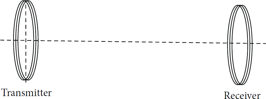
MI communication using mutual induction.
To prolong the communication range, the magnetic-induction (MI) waveguide technique was developed [9, 10], deploying multiple coils between transmitter and receivers as relay node, as is shown in Figure 2. The sinusoidal current in the transmitter coil induces another sinusoidal current in the first relay and so on. The difference between EM based relay and MI based relay is that the MI relay node can be coil without battery and signal process component. Also the path loss of magnetic-induction waveguide is deduced. The closed-form expression of path loss of MI waveguide is analyzed in [9]. In magnetic-induction waveguide technique, only mutual induction between neighborhoods is considered to simplify the analysis. In other words, each relay has mutual induction with two neighbor coils. In ideal MI waveguide, several relay coils are placed along one axis between the MI transmitter coil and MI receiver coil.

MI waveguide technology.
The load impedance and noise model of MI waveguide are analysed in [11], considering the influence of conductivity-based losses in the soil and the frequency-selectivity feature of MI channel. Also the choice of the circuit elements at the relays, the deployment strategies, and the influence on the results are discussed. The channel capacity is maximized by optimizing system parameters, including the transmit power density, the number of coil windings, and the carrier frequency.
In [8–11], all the coils (transmitter, receiver, and relays) have the same parameters, as well as the same resonant frequency. The impedance of transmitter, relays, and receiver is dependent on the transmit frequency. If the transmit frequency is deviated from the resonant frequency, the capacity decreases dramatically. Consequently, the bandwidth is limited in MI communication. In order to solve the bandwidth bottleneck, a spread resonance strategy for MI communication is proposed in [12]. Different resonance frequencies are allocated on different MI relays to increase channel capacity. The spread resonance strategy utilizes tradeoff between larger bandwidth and lower path loss and finds optimal balance. Thus the system complexity is increased remarkably and the waveguide deployment also becomes more difficult.
Another strategy proposed to overcome the throughput bottleneck is to optimize the quality factor of transmitter coil and receiver coil [13]. In magnetic-induction based communication, the transmitter power is a function of quality factor, as well as bandwidth. Thus the capacity can be maximized under optimal value of quality factor.
Besides wireless underground sensor network, the magnetic-induction technology can also be used in other applications under challenging environments, such as underwater communication, body area network (BAN), and embedded medical communication systems [14–17]. Comparing with acoustic wave based communication, the communication range between transmitter and receiver can be increased to hundreds of meters in fresh water by magnetic-induction technique. 3D underwater magnetic-induction wireless networking topologies are modeled for practical shallow and deep water in [15]. Because permeability of the air is the same as that of water, the magnetic-induction channel creates a homogeneous medium between underwater-underwater and underwater-surface areas.
The magnetic-induction waveguide method was studied as a method to increase the communication range in Near Field Magnetic-Induction Communication (NFMIC) in [17]. Unlike EM based wireless communication, the received power of MI based wireless communication does not degrade when the device is inside the human body.
3. MI Based Communication
3.1. MI Based Communication Model
In MI communications, the data transmission and reception are accomplished with the use of a coil of wire. We assume that each node contains one transmitter circuit with a voltage source
The equivalent model of the transmitter and receiver is presented in [2]. The transmitter and receiver circuit can be modeled as one resistor, one capacitor, and one inductor, as illustrated in Figure 3. The transmitted signal is carried by the voltage.

Equivalent circuit of MI communication.
According to Kirchhoff's law and mutual induction theory, the current of transmitter and receiver matches the following equations:

We assume that all coils have the same material and size and thus have the same impedance. The impedance of each circuit is given by

The resistance is determined by the material and the length of the coil:

The induction of each coil can be calculated by

The capacitor of each node is chosen to make each circuit resonant at operating frequency,
By solving (1), the current at transmitter and receivers can be expressed as

When the positions of transmitter and receiver are predetermined, the received power is dependent on the mutual induction between transmitter and receiver.
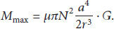
The mutual induction M can be deduced by the magnetic potential of the magnetic dipole:

From (6), the mutual induction between two coils is dependent on the placed angles when the position of coils is determined. Mutual induction reaches its maximum, when the transmitter coil and the receiver coil are vertical to the line connecting the two coil centers,
The transmitted power and received power can be expressed as

Substituting (5) into (8), we can get the transmit power and received power:

The path loss in magnetic-induction communication is defined as the ratio of transmit power and received power,

3.2. Capacity of MI Communication
Assuming all coils are identical and work in resonate frequency, for example, the transmitter coil and receiver coil have the same radius and turns and are made by the same material, they have the same impedance,
Considering Shannon's information theory, the channel capacity can be expressed by


From (12), the path loss varies with operating frequency and reaches its minimum when transmitter works at the resonant frequency,
3.3. Modulation Scheme in MI Communication
Although the magnetic-induction based communication has been studied for a few years, the modulation in magnetic-induction is still an open issue.
The path loss would vary when operation frequency changes, since the impedance of each coil varies with the operation frequency. Different symbol should be sent with the same frequency (resonant frequency) to keep path loss low, such as in MASK and MPSK modulation. Otherwise if the signals were sent by different operating frequency, such as in FSK and GMSK system, different symbol will experience different path loss. The received amplitude of different symbol would be different.
Here, we consider MASK in MI system. Let

4. Capacity of MI MIMO Communication
4.1. MI MISO Communication
When MI transmitter and receiver are equipped with one coil, the communication is referred to as MI SISO communication. In MI SISO communication, the path loss is dependent on the placed angle of each coil and the location of receiver. In this section, the communication model of MI MISO and MI MIMO is proposed, and the channel capacity is analyzed.
4.1.1. MI MISO Communication Model
We consider a magnetic-induction based communication system with two nodes: transmitter (source node) and receiver (destination node). The transmitter is equipped with two coils (T1 and T2), while the receiver is equipped with one coil. The equivalent circuit is shown in Figure 4. Different from MI SISO, mutual induction exists between each two coils. In this case, the receiver can be stimulated by both transmitter coils (T1 and T2). Also there is mutual induction between two transmitter coils (T1 and T2), represented by
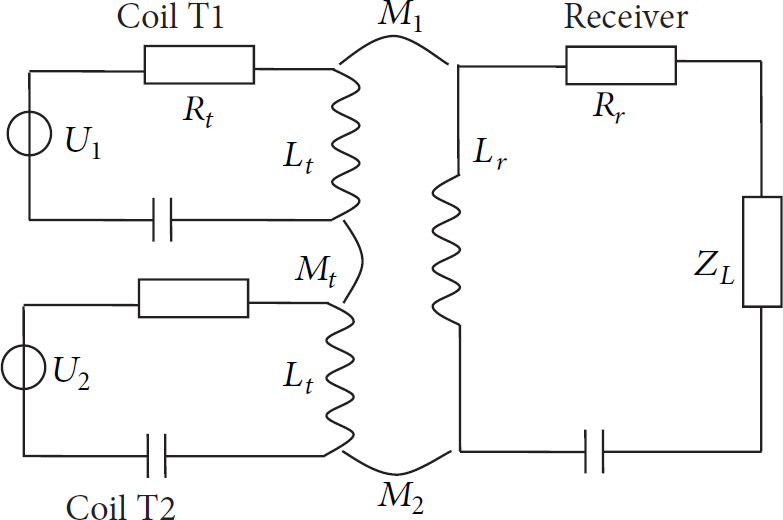
Multiple-input single-output magnetic-induction system.
Assume

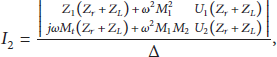
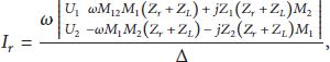
By solving (14), the current in each coil can be deduced as


After calculating the current in the transmitter's coil and receiver's coil, we can get the transmitted power and the received power, respectively. Thus, the transmit and received power are

The path loss in MI MISO system can be calculated considering (19),
From (15) and (16), there is crosstalk between coils T1 and T2 caused by the mutual induction; for example, the voltage of T2 will interfere with the current in T1. The performance can be deteriorated when the transmitter is equipped with two coils because of the crosstalk between two transmitter coils.
4.1.2. Cross Talk Cancellation
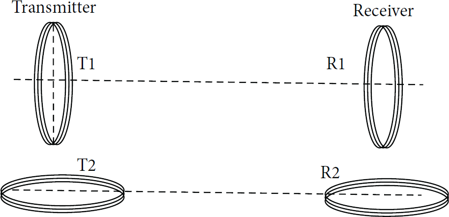
From the analysis above, cross talk exists when multiple coils are deployed in one node (transmitter or receiver). Interestingly, the cross talk can be cancelled by deploying two transmit coils in a special way. We consider one special coil deployment of MI MISO channel model, where the transmitter coil T1 and the receiver coil are vertical to the line connecting the two coil centers, and the line connecting the transmitter coils T1 and T2 is vertical to the line connecting the transmitter and receiver, as is shown in Figure 5.

MI MISO system model when two transmit coils are placed vertically.
We assume that the distance between two transmitter coils is much smaller than that between transmitter and receiver. In this case, the received power is dependent on the placed angle of coil T1.
When coil T2 is placed vertical to coil T1, the mutual induction of two transmitter coils decreases to zero according to (6),

From the analysis above, the transmit cross talk can be cancelled by deploying two transmit coils vertically. The induction on coil T1 caused by coil T2 is reduced to 0. If two receiver coils are deployed in the same way, two parallel links are established.
4.2. MI MIMO Communication
In this subsection, the capacity of MI MIMO is considered, when both transmitter and receiver are equipped with more than one coil. Also, the cross talk is cancelled by the coil deployment method proposed in Section 4.1.2.
4.2.1. MI MIMO Capacity Analysis
Although the coil deployment in MI MISO system in Figure 5 succeeds in canceling the cross talk between two transmit coils, the receiver coil can only receive the signal transmitted by coil T1. To receive the signal transmitted by T2, one horizontal coil R2 would be deployed on receiver. Hence, the MI MISO becomes MI MIMO by adding one horizontal coil, as shown in Figure 6.
Magnetic-induction multiple-input multiple-output communication.
When one coil is placed vertically (T1 in Figure 6) and one coil horizontally (T2 in Figure 6) in transmitter, the mutual induction between two transmit coils becomes 0. Also, the coils are placed in the same way in receiver. When the distance between two coils at one single node (T1 and T2, e.g.) is much shorter than that between transmitter and receiver, the mutual induction between T2 and R1 can be neglected. The current induced in each received coil can be denoted as

The MIMO channel becomes two separate SISO channels. The capacity of MIMO magnetic-induction channel can be deduced as


Here, MI MIMO equals two parallel MI channels; therefore, the robustness is improved by providing one more channel. Each coil transmits signals with the power spectral density
The transmit node and receiver node can be equipped with three coils on each node, comprising three pairs, as is shown in Figure 7. Two coils are parallel with each other in each pair, for example, T1 and R1. Each pair is vertical with another two pairs, for example, T1-R1 and T2-R2. In this case, there are three parallel MI channels between transmit node and receiver node.

Magnetic-induction multiple-input multiple-output system.
Different from MIMO in wireless communication system, MI MIMO can only provide multiplex gain when multiple coils are deployed as Figures 6 and 7. Diversity gain cannot be provided because each receiver coil can only receive signal transmitted by one transmit coil. For example, R1 can only be stimulated by the sinusoidal current in T1. Also, R2 can only be stimulated by T2.
The MI MIMO channel between magnetic-induction transmitter and magnetic-induction receiver is equal to multiple parallel channels.
4.2.2. MI MIMO Capacity Optimization
In this subsection, the power allocation on multiple transmit coils is investigated to optimize the capacity of MI MIMO communication. In MI MIMO system, the transmit power is allocated on multiple transmit coils according to water-filling algorithm. The transmit power allocated on each coil can be expressed as

The value of A can be obtained by substituting all the

The magnetic-induction (MI) waveguide technique was developed to prolong the communication range, by deploying multiple coils between transmitter and receiver as relay node. In order to reduce the computational complexity, we assume that one relay node is stimulated by two neighbor coils in MI based waveguide model; for example, relay i is stimulated by relay
5. Simulation Results
In the simulation section, the parameters are chosen as follows: the resistance of unit length
In Figure 8(a), the mutual induction of two coils at transmitter is given when the coil T2 is placed with the same location but different angle. The transmit coil is placed according to the proposed coil deployment method. The location of receiver coil is illustrated in Figure 5, but the angle varies. From Figure 8, the mutual induction

Mutual induction between two coils.
Then the mutual induction of coil T2 and receiver was simulated in Figure 8(b). From the simulation result, the minimum of
The equivalent mutual induction between transmitter and receiver in MISO communication is simulated in Figure 9; when two transmitter coils are placed as in Figure 5, the receiver coil is located in different direction with the same distance as transmitter; the placed angle of receiver coil is the same as transmitter coil T1. From Figure 9, the directional property is much better than MI SISO. In other words, the receiver would have better performance regardless of its direction. Conversely, the performance of MI SISO is dependent on the receiver's direction.
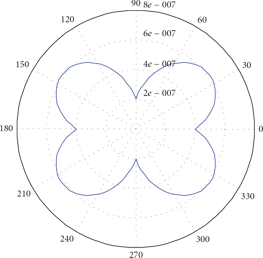
Equivalent mutual induction between transmitter and receiver.
From Figure 10 the path loss in magnetic-induction based communication system is simulated with different transmit frequency. The resonant frequency is assumed to be 10 MHz. The path loss reaches its minimum value at the resonant frequency. When the operating frequency slightly deviates from resonant frequency, the path loss increases dramatically. Also we can observe that the path loss increases with the distance between transmitter and receiver increasing.

Path loss with different distance.
From Figure 11 the path loss in magnetic-induction based communication system is simulated with the resonant frequencies
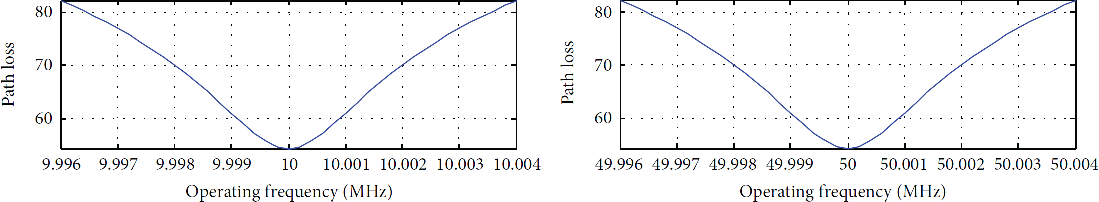
Path loss with different operating frequency.
The capacity of single-input single-output magnetic-induction system and multiple-input multiple-output magnetic-induction system is simulated in Figure 12. In MI SISO system, the transmitted power is allocated on one coil, while in MI MIMO system the transmitted power is allocated on multiple transmitted coils equally. The performance of MI MIMO system outperforms MI SISO system significantly, when the transmit SNR is larger than 27 dB. Thus the MI MIMO is more suitable for high rate applications. In low SNR regime, the MI SISO performs better. When using MI MIMO in low SNR, the power should be allocated on one coil only.
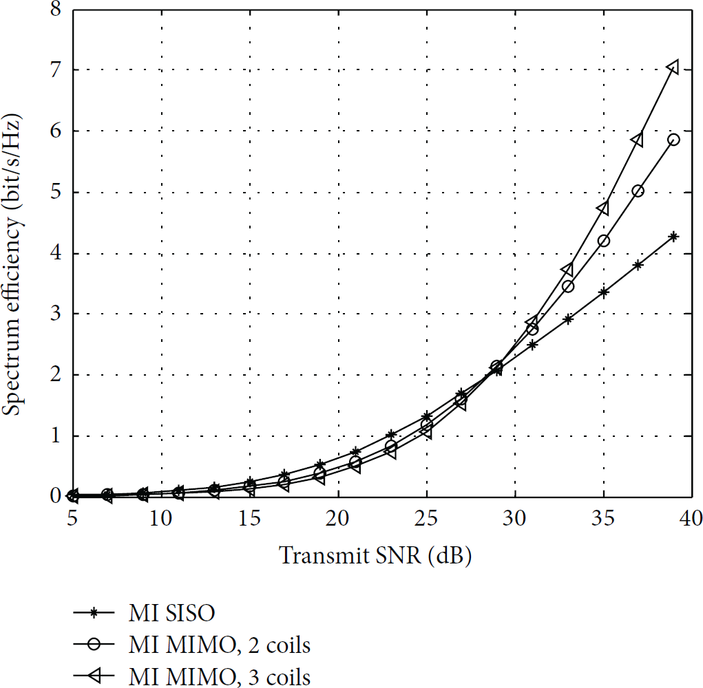
The capacity of magnetic-induction based communication system.
When the power is allocated on each coil optimally, the capacity of MI SISO and MI MIMO system is simulated in Figure 13. In low SNR regime, the MI MIMO system with optimal power allocation (OPA) among multiple transmit coils has the same capacity as magnetic-induction system with one coil. In other words, the power is allocated on one coil only in magnetic system with multiple coils; the other two coils do not transmit data. However, in high SNR regime, the MI MIMO system would outperform magnetic-induction system with one coil.

The capacity of magnetic-induction based communication system.
6. Conclusions
In this paper, the closed-form expression of path loss and capacity of MI based channel are derived. The system model of MI MISO channel is introduced. In order to solve the cross talk when multiple coils are equipped at one node, we introduced a coil deployment method in which each two coils are placed perpendicularly. The channel capacity of MI MISO and MI MIMO communication is derived. Also the capacity can be maximized by power allocation of different coils. The deployment method could also be used in MI waveguide technology to improve the channel capacity and network robustness.
Footnotes
Conflict of Interests
The authors declare that there is no conflict of interests regarding the publication of this paper.
Acknowledgment
This work was supported by the Fundamental Research Funds for the Central Universities (China University of Mining and Technology) under Grant no. 2014ZDPY16.