
Abstract
With the development of the LEO satellite communication technology, highly dependable wireless communication and sensor data collection using LEO satellites have been getting much attention for emergency, marine research, and forest fire disaster in the remote region. The satellite system is expected to have the following features: rapid production, low cost, and fast construction of the satellite network. In this paper, a QS-CDMA uplink access technique in the LEO satellite is presented and discussed, which is focused on the local clocks using GPS 1PPS timing signals and the Doppler compensation for terminal uplink. The spreading code with length of 1023, which is used for the uplink preamble, selects the shift-m-sequence that can greatly reduce the MAI and increase the number of simultaneous access users. A novel analysis method for the accuracy of clock synchronization and a novel method for the estimation of Doppler shift and propagation delay are presented. These methods are used to guide the specific hardware implementation of the QS-CDMA LEO satellite sensor data collection system. Through simulations and experiments, it results in that this system structure can drastically reduce the complexity in implementing the acquisition in the satellite and increase the adaptability of the satellite system in different environments.
1. Introduction
When great disaster occurs, such as earthquake, many terrestrial infrastructures are seriously damaged. We had to take several days to get disaster situation and confirm safety of victims. So we expect that a satellite system provides a minimum reliable connection. The satellite system should have some disaster response features such as safety confirmation and position report. In marine research, oceanographic buoy can transmit information from the submerged nodes, which consist of sensors, to the remote ground station. When forest fire disaster happened in the remote region, the fire sensor transmits alert to the satellite and the satellite forwards the information to the nearest monitor station which maybe a hundred kilometers away. Meanwhile, many different kinds of sensors can collect the information of the forest such as temperature, humidity, and trespass. The satellite system should have some data collection features such as data store and forward. Nowadays the further development of satellite communication has been assisting a very high competition for the discovery of advanced technologies, which have demanded service to support more users and low complexity for satellite payload. In order to collect information of the disaster region in time, the modern trend in Low Earth Orbit (LEO) satellite communications system has to provide reliable short message communication to a large number of user terminals and sensors. An access technique for band-limited quasisynchronous CDMA (BLQS-CDMA) has been proposed in [1], and the network reference clock and frequency are transmitted embedded in the CDMA signal structure using a dedicated code, which is called master code. In [1], the preferentially phased Gold sequences are optimal for BLQS-CDMA with maximum timing jitter of
The modern trend in digital communications is to synchronize with the local time, whose synchronous errors arise from different allowed uncertainties in communication systems. Global Positioning System (GPS) receivers are used by conveying the reference time to the locked-clock loop via the one-pulse-per-second (1PPS) output. It was noticed that the average time error produced by the receivers varied over a range of about 150 nanoseconds (ns) in 2002 [4]. The current production as published showed that jumps are at the 10 ns level [5]. An optimal synchronization of local clocks by GPS one-pulse-per-second (1PPS) timing signals is specified in [6], which use predictive FIR filter. The application of Kalman filter for clock synchronization is proposed in [7]. Nowadays the clock synchronization technique based on GPS has reached a high degree of accuracy.
Generally, in severe Doppler environment, such as the LEO satellite communication, the pseudorandom (PN) code acquisition for the direct-sequence spread spectrum (DSSS) communication is hard to accomplish. The existence of carrier and code Doppler results in a prolonged acquisition process, and it also increased hardware complexity due to the need for a two-dimensional (chip delay and frequency) search structure of code and carrier synchronization. The Doppler characterization for LEO satellites is analyzed in [8]. The direct-sequence spread spectrum code acquisition in the presence of Doppler shift was investigated in [9]. In [10], Doppler compensation loop structure was proposed. In [9, 10], some algorithms have been used to compensate for the Doppler shift by satellites. Due to low-power consumption, which is characteristic of LEO satellites, the acquisition and synchronization structure should meet the requirements of decreasing hardware complexity. At the same time, the satellites need to serve as many users as possible, but the complexity of hardware implementation will limit the number of users.
In this paper, we propose a novel quasisynchronous CDMA (QS-CDMA) transmission scheme based on GPS to increase system capacity, decrease hardware complexity of satellites, provide reliable short message service, and collect data from sensors. The starting point is to analyze the feasibility of implementing local clocks using GPS 1PPS for LEO satellites and terminals. The results will be used to specify the accuracy of clock synchronization. Due to the extremely high Doppler that is an important characteristic of LEO satellites, the acquisition of satellites is significantly simplified by using a continuous wave downlink pilot for uplink carrier Doppler estimation and compensation. The results are shown with the acquisition time performance of satellites that is considerably improved, the number of users is significantly increased and the anti-interception ability is improved. The following sections of this paper are organized as follows: Section 2 describes the overall system architecture and requirements, Section 3 depicts a novel analysis method for accuracy of the clock synchronization technique based on GPS, a novel method of carrier Doppler compensation, propagation delay estimation, and a receiver scheme of satellite, Section 4 introduces the simulation and experiment results, and Section 5 introduces the implementation results and gives a brief conclusion.
2. System Structure and Requirements
2.1. System Structure
2.1.1. System Parameters
The LEO satellite system being considered has the parameters shown in Table 1.
System parameters.

The main differences among QS-CDMA proposed in this paper, BLQS-CDMA in [1], and slotted QS-CDMA in [3] are shown in Table 2.
System comparison.
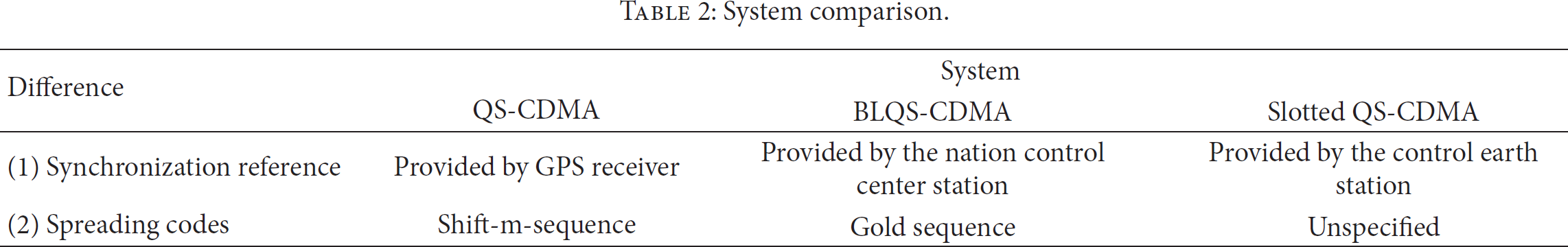
From Table 2, we can know that, the synchronization reference provided by the control station is complex in the middle of ocean. Therefore, synchronization reference provided by GPS receiver is wide applicability.
In Figure 1, the system of interest includes an LEO satellite, a large number of user terminals, sensors, and the GPS system. The LEO satellite broadcasts a continuous pilot carrier for downlink acquisition, tracking, uplink Doppler estimation, and compensation. A high-precision single GPS receiver is required by the LEO satellite. User terminal consists of a GPS receiver chip that offers 1PPS output, a local oven-controlled crystal oscillator (OCXO), or temperature compensated crystal oscillator (TCXO) which is used to form the local time scale with a high-resolution divider, baseband processing module, and so on.

System structure.
2.1.2. System Synchronization Reference
We expect to reduce the complexity and the expense of the QS-CDMA system and increase the adaptability of the system. With the technology development, GPS receiver chip is cheaper and consumes less power. In this paper, GPS receiver should provide accurate synchronization reference. Nowadays the clock synchronization technique based on GPS has reached a high degree of accuracy. So 1PPS signal can meet the requirements. The local clock of the LEO satellite and all user terminals should be aligned with 1PPS as reference. The analysis of the system time synchronization error will be discussed in Section 3.
2.1.3. Doppler Shift, Propagation Delay Compensation, and Access Procedure
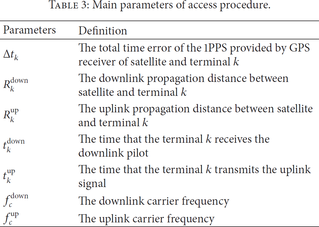
For QS-CDMA access, some main parameters are defined in Table 3. The flow diagram with the proposed access technique is shown in Figure 2.
Main parameters of access procedure.

QS-CDMA access technique flow diagram.
In Figure 2, the QS-CDMA access technique flow diagram can be divided as follows:
(a) Clock synchronization: The local clocks of the LEO satellite and all user terminals align with 1PPS as reference.
(b) Broadcasting pilot: After achieving clock synchronization, the LEO satellite broadcasts a downlink continuous pilot. The pilot frame header aligns with the 1PPS of the satellite, which is used to assist terminals in measuring downlink propagation delay
(c) Downlink propagation delay measurement: Through 1PPS of terminal and the time of pilot frame header reception
(d) Downlink Doppler shift measurement: The terminal measures the downlink carrier Doppler shift and code Doppler shift by the acquisition module and the tracking loop of the terminal receiver. The acquisition module provides the initial Doppler shift. The tracking loop updates Doppler shift in real time.
(e) Uplink propagation delay and Doppler shift estimation: The terminal estimates uplink carrier Doppler shift, code Doppler shift, and uplink propagation delay
(f) Transmitting signal: The terminal transmits signals
(g) QS-CDMA access: At the beginning of next satellite 1PPS, the satellite receives all the uplink signals which achieve QS-CDMA access.
In Figure 3,

QS-CDMA delay compensation based on GPS timing diagram.
2.1.4. Spreading Code for QS-CDMA
Through QS-CDMA access, multiple-access interference (MAI) will be obviously decreased. Selecting the appropriate spreading codes is also important. We proposed that the uplink preamble of the system selects shift-m-sequence whose code length is 1023. The m-sequences possess the following three properties: the balance property, the run property, and the correlation property [11]. If a complete sequence is compared bit-by-bit with any shift of the same sequence, the number of agreements minus the number of disagreements is always −1; that is, there is one more disagreement position than the number of agreement positions. Exploitation of the correlation property of PN sequences makes it possible to design direct sequence spread-spectrum (DSSS) systems.
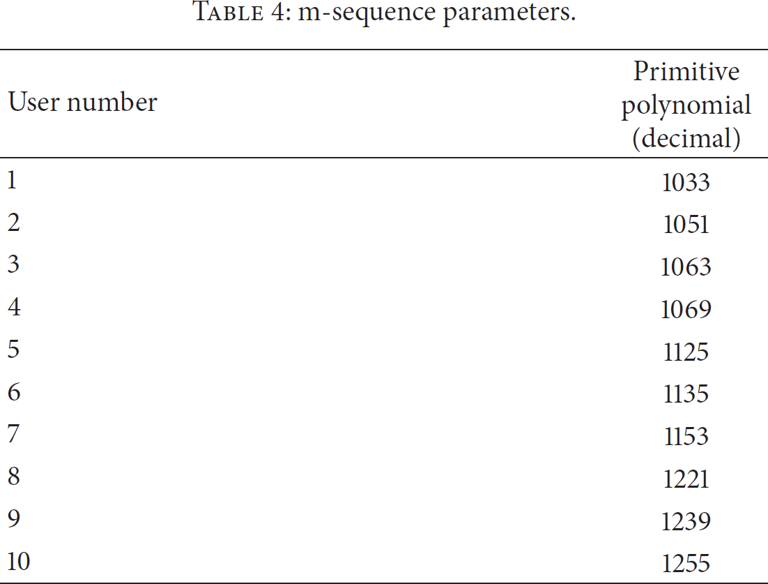
We compare the cross-correlation performance of different m-sequences, whose primitive polynomials are shown in Table 4. We also compare the cross-correlation performance of different Gold sequences whose code length is 1023. We assume that the code phase difference of shift-m-sequence, m-sequences, and Gold sequences is an integer. Normalized cross-correlation is shown in Figure 4.
m-sequence parameters.

Normalized cross-correlation performance.
From Figure 4(a), we can see that the normalized cross-correlation of shift-m-sequences, whose primitive polynomials are 1033, is
Due to the correlation property of m-sequence, the cross-correlation performance of shift-m-sequence is superior. Because any shift-m-sequence is shifted by the same m-sequence, it cannot be acquired in A-CDMA system. However, shift-m-sequence can be used in QS-CDMA system. Every user selects a shift-m-sequence that is different from initial code phase and the code phase interval between one user and the other is greater than or equal to 1 chip. Therefore, through QS-CDMA access with shift-m-sequence, MAI will be obviously decreased.
Theoretically, the QS-CDMA system uses a group of m-sequences whose code length is 1023 and can only provide service to 60 users at one time. The reason is that there are only 60 primitive polynomials for m-sequences with length of 1023. The QS-CDMA system uses a group of shift-m-sequences whose code length is 1023 and can provide service to 1023 users at one time. However, if the code offset of shift-m-sequence is within ±1 code epoch, in order to avoid the self-interference of shift-m-sequences, the number of users is only 341. It means that the smaller code offset is, the more users will be got. Thus, Section 3 will depict a novel method for accuracy of the clock synchronization technique and a novel method of Doppler compensation.
2.2. System Requirements
In order to reduce the LEO satellite implementation complexity and the multiple-access interference (MAI), the system requires limiting the carrier Doppler shift to be within ±0.5 Rb, where Rb is the bit rate of data, and the code offset to be within ±1 code epoch at 5 million chips per second (Mchip/s). By assuming that the proposed Doppler compensation meets the requirements, acquisition structure is demonstrated to be feasible with acceptable acquisition time by a 1-dimensional serial search instead of the considerably longer 2-dimensional search that will be required in the uncompensated case.
The requirements for the code offset in different code rate are shown in Table 5.
Requirements for the code offset.

From Table 5, it is shown that the higher code rate is, the more stringently the requirement for code offset is.
3. Implementation Architecture and Performance Analysis
In this section, the key features of the QS-CDMA access technique will be studied in depth. Through the 1PPS, all users that use random spread spectrum codes employ slotted ALOHA (S-ALOHA) random access protocol. The pilot broadcasts the codes which collided with each other, and then the users repeat to transmit with spread spectrum random codes at next 1PPS or next slot.
3.1. Downlink Pilot and Uplink Preamble Frame Structure
Downlink pilot structure consists of pilot frame header, PN code indication, and contents. The pilot frame header is aligned with 1PPS of satellite and used for all user acquisition. The PN code indication denotes the codes which collided with each other (see Figure 5).

Frame structure: (a) downlink pilot structure, (b) uplink data structure.
Uplink structure consists of preamble, frame header, and contents. The preamble is also aligned with 1PPS of terminal and is used for satellite acquisition. The frame header indicates the beginning of the contents.
All user terminals select a shift-m-sequence from a group of sequences, whose code length is 1023, for the uplink preamble of the system. Because of QS-CDMA access technique, the code phase of preamble should be predefined, so the acquisition of satellite will be easy to capture the signals from terminal, and the time of preamble should be shortened. The short preamble which is spread by shift-m-sequence will increase ability to anti-intercept. Meanwhile, the shorter the preamble is, the more system capacity we will obtain.
3.2. Analysis of Clock Synchronization Time Error Based on GPS
In this paper, we assume that the average time error of the 1PPS produced by GPS receivers of satellite varied over a range of about 10 ns and 100 ns by terminal receivers. Nowadays, these errors are common errors and the ranges can be easy to be achieved [5]. The local clock synchronization block diagram is shown in Figure 6.

Local clock synchronization block diagram.
In Figure 6, we can see that the lead-lag comparator compares the 1PPS from GPS receiver and the local 1PPS. Through finite impulse response (FIR), the time error drives the direct digital synthesizer (DDS) to generate frequency control word. Finally, the local 1PPS generator provides the local 1PPS at a 40 MHz work clock.
Some main analysis parameters are defined in Table 6.
Main parameters of clock synchronization analysis.

For propagation delay compensation, in Figure 3, the delay 
The measurement accuracy of the 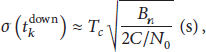
Normally,
The ionospheric time-delay is computed as follows [12]:

To achieve QS-CDMA access, the terminals estimate the uplink propagation delay through 

Substituting (1) and (5) into (4), 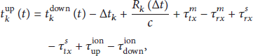
In above equation, the parameters are decided for the accuracy of
3.2.1. Time Error
The local clock synchronization is similar to PLL. One metric that is normally used to determine if loss of lock has occurred in a PLL is the total phase jitter, which is defined as [12]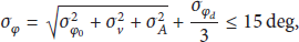
For the local clock synchronization, oscillator jitter is the prime jitter. The phase jitter 
Coefficients in TCXO and OCXO clock error models.


Phase jitter from clock.
The loop order is sensitive to the same order of dynamics, and the loop bandwidth must be wide enough to accommodate these higher-order dynamics. The first order is sensitive to velocity stress, second order to acceleration stress, and third order to jerk stress. For the local clock synchronization, the oscillator jitter is the prime jitter. The thermal noise and dynamic stress error have less effect on the time jitter of the local clock synchronization, in Figure 7, and increasing the one sided PLL loop bandwidth reduces the phase jitter; then the oscillator jitter can be neglected. So 
3.2.2. The Delay Time Difference between Transmitter and Receiver of Terminal
The delay time difference is the parameters of device design and can generally be controlled below 50 ns.
3.2.3. The Delay Time Difference between Transmitter and Receiver of Satellite
The delay time difference can generally be controlled below 30 ns.
3.2.4. The Ionospheric Time-Delay Difference between Uplink and Downlink
At the carrier center frequency, 
3.2.5. The Time Light Travels for the Varied Distance between Satellite and Terminal
The value is the time that electromagnetic wave travels for the varied distance between satellite and terminal when terminal estimates the propagation delay and waits to transmit. The accuracy of varied distance delay estimation can be achieved within 100 ns, so
In short, the estimation error of the uplink propagation delay is computed as follows:

3.3. Doppler Shift and Propagation Delay Compensation
In this paper, we assume that orbit altitude is 1000 km and maximum elevation angle is 90 degrees, so the visibility time is approximately 9 minutes. Some parameters are defined in Table 8.
Main parameters of compensation analysis.

3.3.1. Carrier Doppler Shift and Propagation Delay
When the elevation angle is 90 degrees, we define that t is 0 seconds. The carrier Doppler shift is computed as follows [8]:


(a) Distance versus time, (b) time-delay versus time, (c) Doppler shift versus time, and (d) Doppler shift rate versus time.
In Figure 8(a), we can see the relationship between propagation delay and time. In Figure 8(b), we can see the relationship between propagation time-delay and time. In Figure 8(c), we can see the relationship between carrier Doppler shift and time. In Figure 8(d), we can see the relationship between carrier Doppler shift rate and time. We assume that satellite begins to be in vision when t is −450 s. At this point, the value for the distance L, the time-delay, and the Doppler shift are all the maximum, and the Doppler shift rate is the minimum. At the same time, the
3.3.2. The Analysis and Estimation Method to Carrier Doppler Shift and
We suggest using the following method to estimate carrier Doppler shift and
Through the estimation of downlink carrier and chip frequency offered by receiver's tracking loop, the uplink carrier and code Doppler shift can be accurately computed. The
Firstly, we have to analyze the terminal receiver's FLL, PLL, and DLL tracking loop measurement errors that directly affect the accuracy of uplink Doppler shift and propagation delay compensation.
We assume that the received signal power is −120 dBmW; noise power spectral density

Tracking loop measurement errors.
In Figure 9(a), we can see the relationship between total frequency lock loop (FLL) jitter and time. In Figure 9(b), we can see the relationship between FLL dynamic stress and time. In Figure 9(c), we can see the relationship between total PLL jitter and time. In Figure 9(d), we can see the relationship between phase lock loop (PLL) dynamic stress and time. In Figure 9(e), we can see the relationship between total code tracking loop (DLL) jitter and time. In Figure 9(f), we can see the relationship between DLL dynamic stress and time. From Figure 9, we can see that the terminal receiver's FLL, PLL, and DLL tracking loop measurement errors have less effect on Doppler shift compensation at high
Secondly, we will analyze the frequency deviation caused by the TCXO with frequency stability of ±0.5 ppm or OCXO with frequency stability of ±0.05 ppm. The signal conditioned RF signals are down-converted to an intermediate frequency (IF) using signal mixing frequencies from local oscillators. The local oscillators are derived from the reference oscillator by the frequency synthesizer, based on the TCXO or OCXO. At downlink carrier frequency which is 1.5 GHz, the most frequency deviation of the frequency synthesizer, caused by TCXO, is ±750 Hz, and the most frequency deviation caused by OCXO is ±75 Hz. After the mixing process, at the IF, this frequency deviation is a fixed bias that will be additional carrier Doppler shift. From Figure 8, we can see that the maximum carrier Doppler shift rate is far less than 1/2 data rate in the time when signal is transmitted from the transmitter of satellite to the receiver of terminal. The tracking loop measurement error is less than 1 Hz. We assume that the satellite and terminal use the same TCXO or OCXO. The estimation error of uplink carrier Doppler shift can be given as follows:

Finally, through the estimation of downlink carrier and chip frequency offered by receiver's tracking loop, we can compute the
We compute the

(a) Theoretic estimation error, (b) estimation error with TCXO, and (c) estimation error with OCXO.

(a) Theoretic estimation error, (b) estimation error with TCXO, and (c) estimation error with OCXO.
In Figure 10(a), we can see the relationship between theoretic estimation error and time. Because estimation of the varied distance
In Figure 11(a), we can see the relationship between theoretic estimation error and time, where theoretic estimation means that the frequency deviation is 0 Hz. In Figure 11(b), we can see the relationship between estimation error with TCXO and time. In Figure 11(c), we can see the relationship between estimation error with OCXO and time. The time is between −1 s and 0 s.
From Figure 10(a), when t is −450 s, we can get the sum of varied distance estimation error in one second, and the accuracy of compensation for
In the visibility time, which is approximately 9 minutes, estimation errors through simulations are shown in Figure 12.

(a) Theoretic estimation error, (b) estimation error with TCXO, (c) estimation error with OCXO, and (d) estimation error versus estimation error of uplink Doppler shift.
In Figure 12(a), we can see the relationship between theoretic accumulative estimation error in one second and time. In Figure 12(b), we can see the relationship between accumulative estimation error in one second with TCXO and time when estimation error of uplink carrier Doppler shift is 1200 Hz. In Figure 12(c), we can see the relationship between accumulative estimation error in one second with OCXO and time when estimation error of uplink carrier Doppler shift is 110 Hz. The time is between −450 s and 450 s. In Figure 12(d), we can see the relationship between accumulative estimation error and estimation error of uplink carrier Doppler shift.
From Figures 12(a), 12(b), and 12(c), we can see that the carrier Doppler shift rate has effect on the estimation error of the varied distance
From Figure 12(d), we can see that the more estimation error of uplink carrier Doppler shift is, the more estimation error of the varied distance
From the above analysis, carrier Doppler shift and propagation delay compensation of terminal, based on the OCXO with frequency stability of ±0.05 ppm, can match the requirements of the QS-CDMA system. Because the prime estimation error is the average time error of the 1PPS produced by terminal receivers, the current production showed that jumps are much less than 100 ns [4]. Through (11), it results that the OCXO with frequency stability of ±0.1 ppm can also meet the requirements for the clock synchronization time error in practice.
3.4. Analysis of Error Probability
The QS-CDMA sensor data collection system proposed in this paper mainly focuses on the following applications: emergency, marine research, and forest fire disaster. For emergency, such as earthquake, people use terminals to transmit safety confirmation in the safety and open area. For marine research, the oceanographic buoys are scattered distribution in the vast ocean. For forest fire disaster, we recommend that the sinks placed in high or open place collect information from sensors, and the sinks transmit information of forest to the LEO satellite. Therefore, the satellite channel can be considered that there is a line-of-sight (LOS), which is a dominant stationary signal component.
BER performance in the presence of additive white Gaussian noise (AWGN) and cochannel interference is derived.
Through the BPSK modulation, the jth user transmitted signal can be represented as

The received signal at the demodulator input can be represented as

The received signal after down-converting is filtered with a chip matched filter. When the carrier frequency offset is not concerned, the signal after being sampled at the chip rate can be simplified as

In [1], the probability of error for QPSK has been derived. We can use the same method to derive the BER of BPSK. It can be shown that, supposing that all the 

According to the analysis of Section 3, we assume that
Figure 13 shows the theory BER curves of three systems. The Asynchronous Code Division Multiple Access (ACDMA dots) approaches a constant for different number of users. When the number of users is much more, the BER performance of ACDMA is so bad that the data of lth user cannot be demodulated. The QSCDMA-I (dashed line) uses Gold sequence to spread spectrum. We can see that the BER performance of the QSCDMA-I is much better than that of the ACDMA. Unfortunately, with the increase of the number of users, the Gold sequences lose a lot of the BER performance. The QSCDMA-II (continuous line) uses shift-m-sequence to spread spectrum. Because

BER curves of ACDMA, QSCDMA-I, and QSCDMA-II.
From Figure 13, we can see that the loss of BER performance in QSCDMA-II system increases much slower than in QSCDMA-I system as the number of users grows. Therefore, the MAI of QSCDMA-II system is obviously decreased.
4. Simulation and Experiment Results
In this section, we present simulation and experiment results in order to validate the performance of QS-CDMA system. BER performance in the presence of additive white Gaussian noise (AWGN) and cochannel interference is analyzed.
We assume that the power of all users is equal. There are 341 users who are transmitting data at the same time. Because
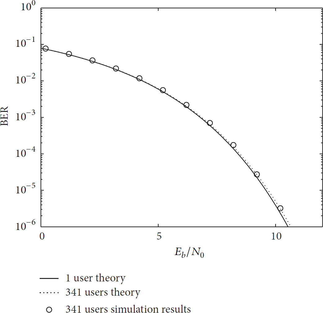
QSCDMA-II simulation BER.
Figure 14 shows that the simulation results of QSCDMA-II are in accordance with the theoretical prediction. Therefore, the uplink preamble of the system selects such shift-m-sequence that the system can achieve much better BER performance and serve more users. The MAI of the system can be obviously decreased.
From simulation results, we can see that the performance of BER is excellent, when the power of all users is equal. Then we mainly consider the situations that the power of every user is not equal by experiments. The experiment environment consists of several terminals and one satellite simulator. The main functions of the satellite simulator are to simulate the changes of Doppler shift, Doppler shift rate, and propagation delay. We tested the performance of BER in several situations. The situations are shown in Table 9. We also assume that
Several situations.
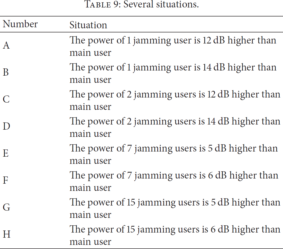
Experiment results.

From Table 10, we compare numbers 1, 2, and 3 with numbers 7, 8, and 9 and can see that the BER performance of QS-CDMA system is a little better than A-CDMA system. We compare numbers 4, 5, and 6 with numbers 11, 12, and 13 and can see that the BER performance of QS-CDMA system is also a little better than the A-CDMA system. The prime reason of this phenomenon, which is different from the results in Figure 14, is that the power of jamming users is far more than main user. Thus the power control is important in QS-CDMA system, too.
5. Conclusions
In the paper, a quasisynchronous CDMA uplink access technique in the LEO satellite has been presented and discussed. From the analysis of clock synchronization time error based on GPS, the novel system structure based on GPS 1PPS is shown to code offset which is less than 1 chip at 5 Mchip/s, and the effect of the multiple-access interference can be greatly reduced. The effect on Doppler compensation, caused by the frequency stability of terminal's oscillator, is analyzed emphatically. It results that, by Doppler compensation, we can reduce the time of acquisition and the complexity of implementation in satellite. These methods are used to guide the specific hardware implementation of the QS-CDMA. The FPGA implementation can be proved that Doppler compensation can achieve the requirements of QS-CDMA system, the probability of error is drastically reduced compared to A-CDMA system, and the number of users is drastically increased. The QS-CDMA sensor data collection system proposed in this paper mainly focuses on the following applications: emergency, marine research, and forest fire disaster. The QS-CDMA system is easy to implement, use in remote, and collect data from more sensors. Meanwhile, the system can respond quickly to emergencies.
Footnotes
Conflict of Interests
The authors declare that there is no conflict of interests regarding the publication of this paper.
Acknowledgment
This work has been supported by Shanghai Natural Science Foundation (12ZR1450000 and 15ZR1439400).