
Abstract
A 2.45 GHz active integrated ZigBee RFID system embedded with GPS is developed with an automated switching protocol algorithm utilizing wireless sensor network (WSN) platform to track the physical belongings or people in indoor and outdoor environments within a control area. In addition, to make the system contactless when the tag is not joining the network, the function of global system for mobile (GSM) communication is added to the integration. The communication between RFID reader and RFID tags is via WSN platform that supports mesh network and self-healing mechanism. Energy efficiency, robustness, and reliability are key factors in the design algorithm of the system. Comparisons are made between the existing active RFID system and the proposed active RFID system to study the performance of the proposed RFID system with an automated switching algorithm implemented on it. Based on the experimental study and statistical analysis done for all situations, a conclusion has been made where the proposed embedded RFID tag provided better signal propagation compared to the existing RFID tag and the battery lifetime for embedded RFID tag with switching mechanism is better than without switching mechanism.
1. Introduction
RFID and WSN are two important wireless technologies that have a wide variety of applications in current and future systems. There are a number of advantages to merging these two technologies. RFID tags are much cheaper than sensor nodes. It is economical to use RFID tags to replace some of the sensor nodes in WSN. Moreover, because an object that is embedded with an RFID tag is trackable, RFID technology provides a reasonable addition to WSN in tracking objects that otherwise are difficult to sense especially in an indoor environment. On the other hand, WSN offers a number of advantages over traditional RFID systems [1]. Sensors can provide various sensing capabilities to RFID tags, push logic into nodes to enable RFID readers and tags to have intelligence, and provide the RFID system with the capability of operating in multihop communication, which potentially can extend the applications of RFIDs. In addition, GPS is the best solution to track the outdoor location since it is unable to work completely indoors or in an environment with obstacles and GSM is for global communication. By adding GPS and GSM into RFID and WSN, a comprehensive system is developed which can provide both positioning technologies within either a control area or a global area.
Recently, most of the researchers focused on the tracking such as buses, containers, logistics, vehicles, humans, and assets only for indoor or outdoor environment [2–10]. However, little has been done in the tracking of both Indoor and outdoor location especially using WSN platform [6]. Due to this reason, the embedment between RFID, GPS, GSM, and WSN is the main contribution part and the automated switching algorithm is implemented to facilitate indoor and outdoor location tracking simultaneously as presented in previous work [11]; thus this new paper is a continued work from the previous publication in [11]. The algorithm developed includes multimode configuration; sleep and continuous mode, multiprotocol; reader talk first (RTF) and tag talk first (TTF) and multimode communication; and application programming interface (API) mode and application transparent (AT) mode.
2. Literature Review
US Patent 20080030306 A1 [12] describes an RFID device that is an active transponder which includes a transmitter, a receiver, and a microprocessor. The invention relates RFID devices to many applications, for example, for determining the location of objects or person that is tagged with RFID tag. However, the document does not describe any additional solutions on how to monitor or locate the objects or persons especially for an indoor and outdoor location environment, respectively. US Patent 20090085745 A1 [13] describes an RFID tracking device that includes a GPS capable of detecting the unique identification (ID) from the RFID tag of the objects and obtaining the location coordinate provided by GPS. However GPS is unable to work completely indoors or in an environment with obstacles which thus contributes to the weaknesses of the design. The WO 2003050960 A2 [2] is another patented system that combines the RFID and GPS functionality on intelligent label. The system used active RFID reader and GPS to track the location and send the location data information to the RFID reader in short distances only without involving WSN platform. This system is however unable to work completely indoors or in an environment with obstacles. The EP 1752908 A2/2006 [3] is another patented system that integrates the GPS functionalities in a portable RFID system to track the location of an object or pallet inside or outside the structures such as warehouses and the factory automation environment. However this system integrates the GPS receiver on the RFID reader portion to track the location and send the information to the monitoring station via wireless transceiver in short distances without introducing WSN platform. This is in contrast with the proposed embedded RFID system that utilized the GPS function on the RFID tag portion to track the location.
Real time location system (RLTS) with ZigBee Technology (EP 2196816 A1/2008) [4] is another work using a similar ZigBee Technology IEEE 802.15.4/ZigBee standard as the proposed embedded RFID tag that operates in unlicensed frequency bands (868 MHz in Europe, 915 MHz in USA, and 2.4 GHz almost worldwide). The system involved WSN in the implementation; however, the system only provides location tracking for indoor environment without integration with GPS technology. US 20090043504 A1 [5] develops a system and method for locating, tracking, and monitoring the status of personnel and/or asserts. However the system did not involve RFID or GPS technology and only focuses on a computer-implemented method for generating a position estimation of a tracker in an indoor location. A most similar system developed by Numerex and Savi Technology [6], a hybrid tag that includes active RFID, GPS, satellite communication, and sensors, introduces an automated switching mechanism; however, the system has different approach from the proposed embedded RFID tag. The system combined satellite communication and GPS tracking with 433 MHz active RFID into a single device controlled by a microprocessor without introducing WSN in their platform. The satellite system hardware is expensive and each time the tag communicates with the satellite system, a fee is charged which contributes to the system drawback.
Therefore, a better solution is needed to improve the existing RFID system by the development of a 2.45 GHz active RFID tag with automated switching mechanism between GPS and RFID tracking which utilized GSM and WSN platform with the capabilities of M2M communication between RFID reader and RFID tags. The GSM communication is available only when the RFID tag is not joining the network; the designed method reduces the cost of the embedded RFID tag compared to previous work [6] which used satellite communication as a medium of transmission when the tag is not in the reader read range. Table 1 shows a brief comparison between previous system and proposed system that is related to indoor and outdoor tracking.
Comparison of existing and proposed system.

3. System Design
In this work, the embedded RFID tag communicates with the RFID reader via WSN platform. The WSN consists of routers that are utilized to route the data from RFID reader to RFID tag or otherwise. The major factors considered in the design are energy efficiency, robustness, and reliability. The embedded RFID tags are battery powered and therefore, to increase network lifetime, energy must be saved in every hardware and software solution composing the network architecture. Data communication is responsible for the greatest weight in the energy budget when compared with data sensing and processing [14]. In previous work done by [14], they use short range communication using optimal spacing between nodes to reduce the energy consumption by about 15% to 38% depending on the network density. Therefore it is desirable to use short range communication instead of long range communication between nodes in WSN platform. Thus in this work, the embedded RFID tag is preset with minimum power transmission to reduce the energy consumption as suggested by [14]. Another way to minimize the energy consumption is by optimizing the data volume to be transmitted, signal processing in the RFID tag, and the percentage of time the embedded RFID tag is on by using sleep/awake protocol algorithm as suggested by [7]. In addition, the energy harvesting technology also can be used to increase the WSN network lifetime [15–17]. The RFID reader and routers, on the other hand, do not necessarily have strict restrictions on energy and processing power since they are powered by fixed supply.
The GPS receiver embedded with the RFID tag utilized in this work used National Marine Electronic Association (NMEA 0183) protocol that is capable of estimating the location information with 3.3 m accuracy without aid of satellite based augmentation system (SBAS). The active antenna on board helps the system integrators to do the system design easily. The standard update rate is 1 Hz and can be up to 5 Hz as well. The current consumption during acquisition is 63 mA; however, it will become lower while tracking by about 59 mA for first 5 minutes, 42 mA after 5 minutes, and 33 mA after 20 minutes. The standard output sentences are GGA, GLL, GSA, GSV, RMC, VTG, and ZDA [18].
The embedded RFID tag is periodically sent out location data from GPS receiver to RFID reader via WSN platform at monitoring station to track and trace the movement and sequences location of the tagged person or item only when having valid GPS data from satellites. However if there are no valid data from satellites, the localization will be done by RFID tag using RSS values retrieved from the proposed embedded RFID tag. The RSS value can be requested manually or automatically from the RFID reader which later is used to calculate the distance from the RFID routers which have fixed data location. However, this approach may delay accessing the required information. A compromise between delay and power efficiency can be achieved by optimally selecting the interval for periodic transmission of required data. The location information of the embedded RFID tag along with the time stamp and identification number is transmitted to the RFID reader periodically to the monitoring station. Periodic transmission of location information facilitates continuous monitoring but leads to increased power consumption and bandwidth occupancy.
The subsections to follow elaborate the embedded RFID tag, RFID reader, protocols, and algorithms involved in the GPS RFID WSN based tracking system.
3.1. Embedded Active RFID Tag with GPS Functionalities
The motivation of this embedded RFID system is to provide users with a technology that can track and trace their physical belonging, assets, vehicles, humans, or animal remotely from a monitoring station using WSN platform by providing the identification and location data as well as contributing to the M2M communication without human intervention. The system is also suitable to be used in supply chain management, medical emergencies, and crowd control application and the most popular application demand recently is to support information and communication technologies in collaboration during emergency response and disaster management. With the aid of this embedded RFID system, all the information about the conditions can be obtained and problems regarding to the application can be solved remotely. Thus the embedded RFID system can reduce the manpower use in each management system as well as reducing the cost of labour.
The novelty of the proposed embedded RFID tag developed in this work is an automated switching protocol of indoor and outdoor location tracking and monitoring system which includes a microcontroller embedded with a GPS receiver together with a wireless communication module and GSM modem to become a single RFID tag which can be used to transmit and receive data from/to the RFID reader. The embedded RFID tag with the cooperation of the RFID routers will form a WSN network that can cover a large area of data transmission and reception. The embedded RFID tag is an active RFID that communicates with the RFID reader system at a frequency of 2.45 GHz ISM band that has an ability to transfer the location data to the active RFID reader in a range of 60 m indoors and 1500 m outdoors and can be extended to more than 1500 m via RFID router in multihop communication using WSN platform [1]. The embedment of GSM communication is to support the global communication especially when the embedded RFID tag is not in the wireless network coverage area. However, as long as the embedded RFID tag is covered by the wireless network, the GSM modem will not be activated. The embedded RFID tag is battery powered and therefore requires power efficient hardware and minimum amount of signal processing. Due to these reasons, an algorithm based on AT mode and cyclic sleep mechanism is implemented to minimize the amount of signal processing and reduce the power consumption. Figures 1 and 2 show the block diagram of the existing RFID tag [19] and proposed embedded RFID tag that is implemented in this work.
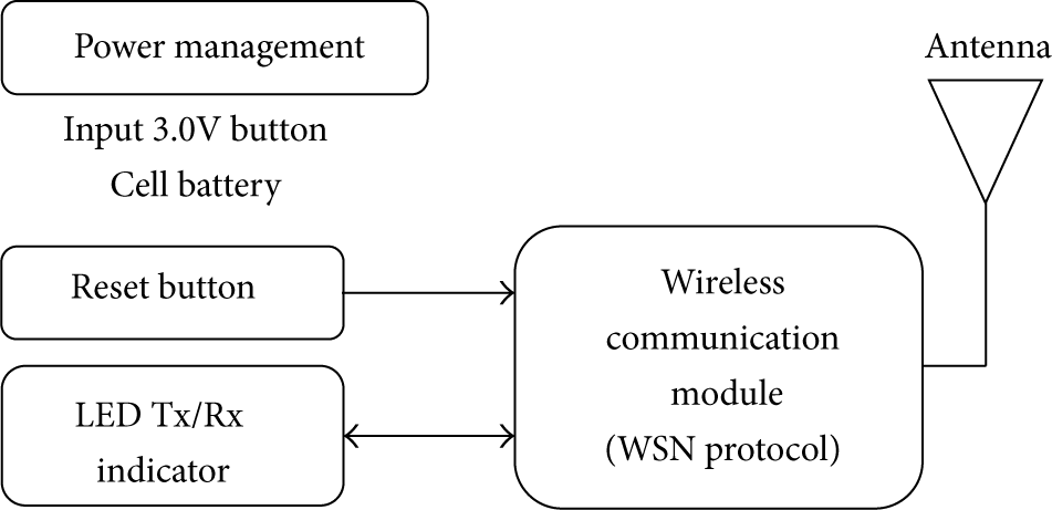
Block diagram of the existing RFID tag [19].
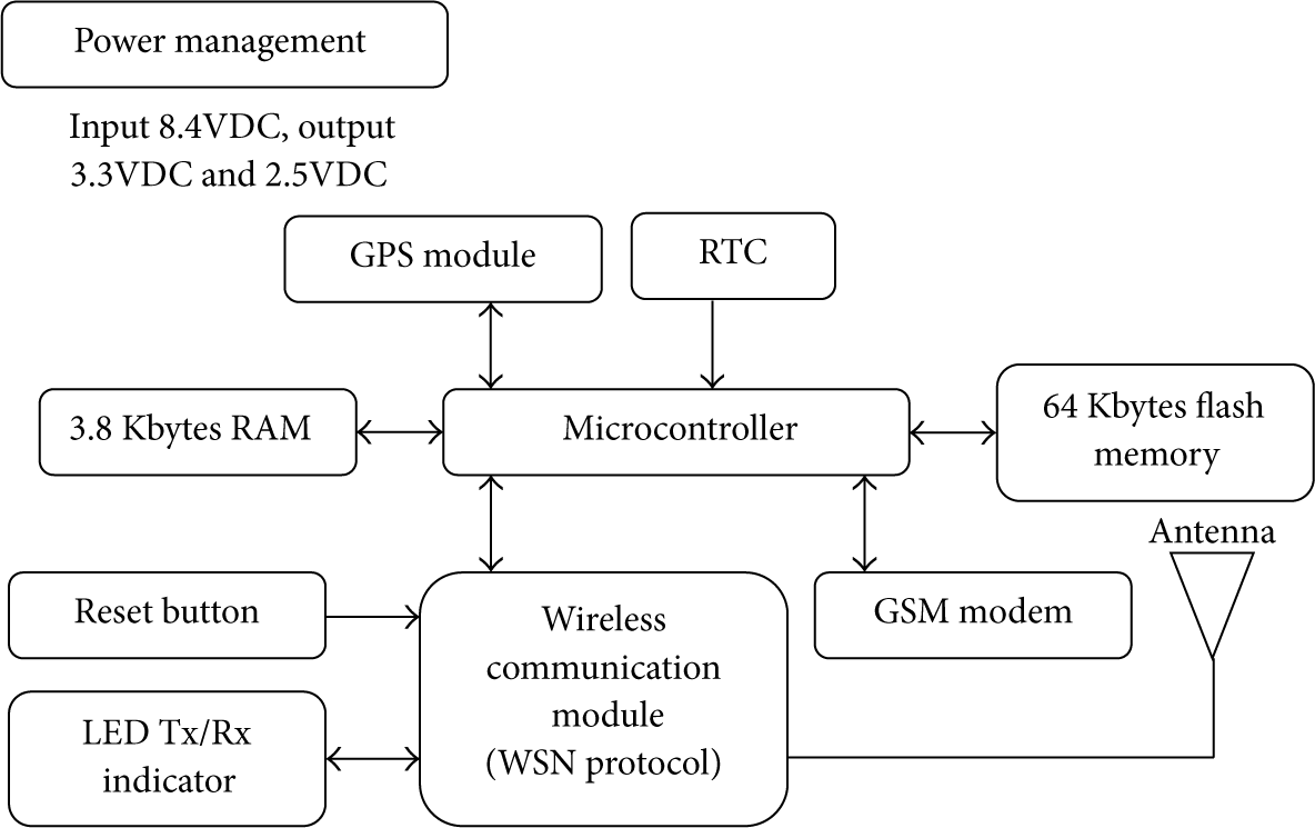
Block diagram of the proposed embedded RFID tag.
3.2. Active RFID Reader
The application of RFID is a good choice in M2M communication as proposed in [19] and [20] and as such it is appropriate to be used in this proposed RFID system. Figure 3 shows the block diagram of the existing active RFID reader [19] while Figure 4 shows the block diagram of the proposed active RFID reader that is implemented in this work. The proposed active RFID reader consists of a wireless communication module, two control buttons and real time clock connected to a microcontroller, and RS232 driver board for interfacing with a personal computer located at the monitoring station. The location is periodically sent from the embedded RFID tag to RFID reader along with its ID, longitude, latitude, and timestamp.

Block diagram of the existing active RFID reader [19].
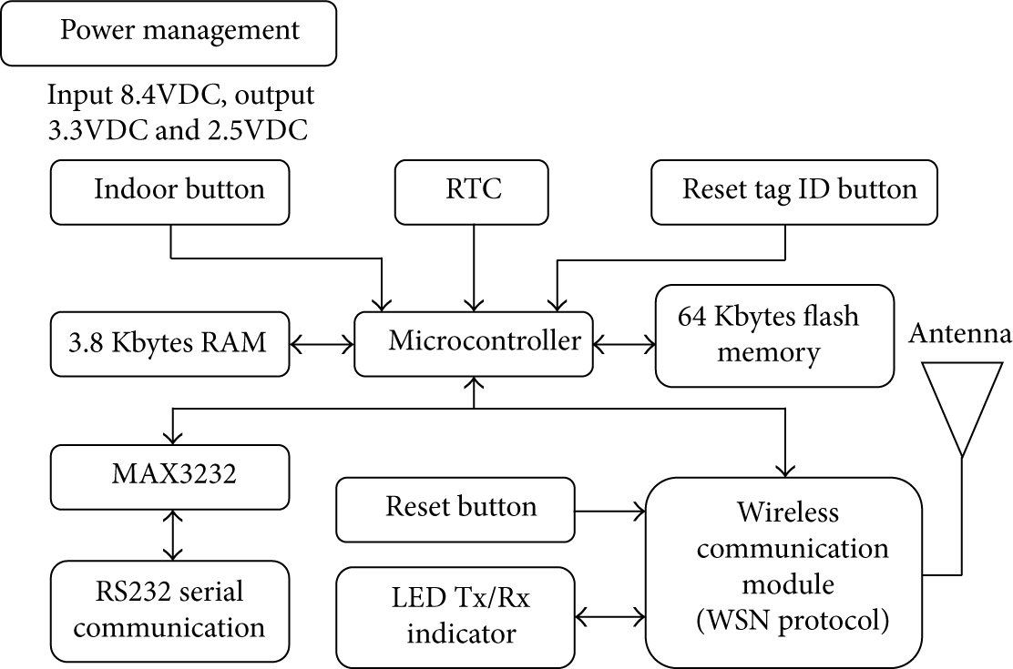
Block diagram of the proposed active RFID reader.
Whenever there is a need to locate items or persons that cannot be detected by the GPS receiver, the RFID reader shall broadcast a command. Each embedded RFID tag received a command and checks whether satellites detect their location or not. If not, the embedded RFID tag will send an acknowledgment and the ID along with RSS value to the RFID reader to indicate their location and distance and turn to sleep mode to reduce energy consumption. If there is a satellites reception, the embedded RFID tag will remain silent (no acknowledgment) and continue with data reception from GPS receiver and periodically send location information to the RFID reader. The RFID RS 232 driver board is added to RFID reader for serial data transmission and reception to or from the computer at the monitoring station and is powered up by a fixed power supply of 9 VDC. All communications in RFID reader system and RFID router are configured in API mode.
3.3. Communication Protocols and Algorithms
The minimization of energy consumptions highly relies on the processing and communication requirements of the protocols and algorithms at various layers of the RFID system. The communication protocol defines how to exchange instruction and data between reader and tag in both directions. The ISO 18000-4 has suggested the usage of RTF protocol in 2.45 GHz active RFID system [21]. The concept of this protocol is that any tag shall not perform data transmission unless it has received and properly decoded the instruction sent by the reader. RTF protocol is identified as one of the solutions for anticollision in multitag communication [22] and is an effective way to reduce energy consumption of the RFID tag [23].
The proposed active RFID system employed multiprotocol communication: RTF and TTF. The TTF protocol is implemented when the tag is having valid location data from GPS receiver. The method of switching from one protocol to another can be many ways. For example, active RFID tag listens to RFID reader broadcast command before switching from RTF to TTF mode [24]. Meanwhile, in [25], the RFID tag is switchable between TTF and RTF mode within a switching time frame based on RFID tag's transceiver configuration. In this work, the automated switching algorithm is based on the data location provided by the GPS receiver. If the location is detected by the GPS receiver, the embedded RFID tag will activate the TTF protocol and send the location data to the RFID reader. If the location is not detected by the GPS receiver, the embedded RFID tag will turn to sleep mode and wake up periodically within certain time frame to sense the incoming signal from RFID reader. At this point, the RFID tag will automatically switch from TTF to RTF mode and wait for interrogation signal from RFID reader asking for the indoor location data. Instead of indoor location monitoring, the RFID reader also used RTF mode to resetting the tag ID from the host computer to a specific embedded RFID tag and thus this function contributes to the M2M communication to change RFID tag's information from the RFID reader. All communications described in this work are assumed in WSN platform; however if the embedded RFID tag is not in the WSN coverage, the GSM communication will be activated. Figures 5(a) and 5(b) show the algorithm flow chart of the active RFID reader and tag with the ability of switching mechanism for indoor and outdoor application.
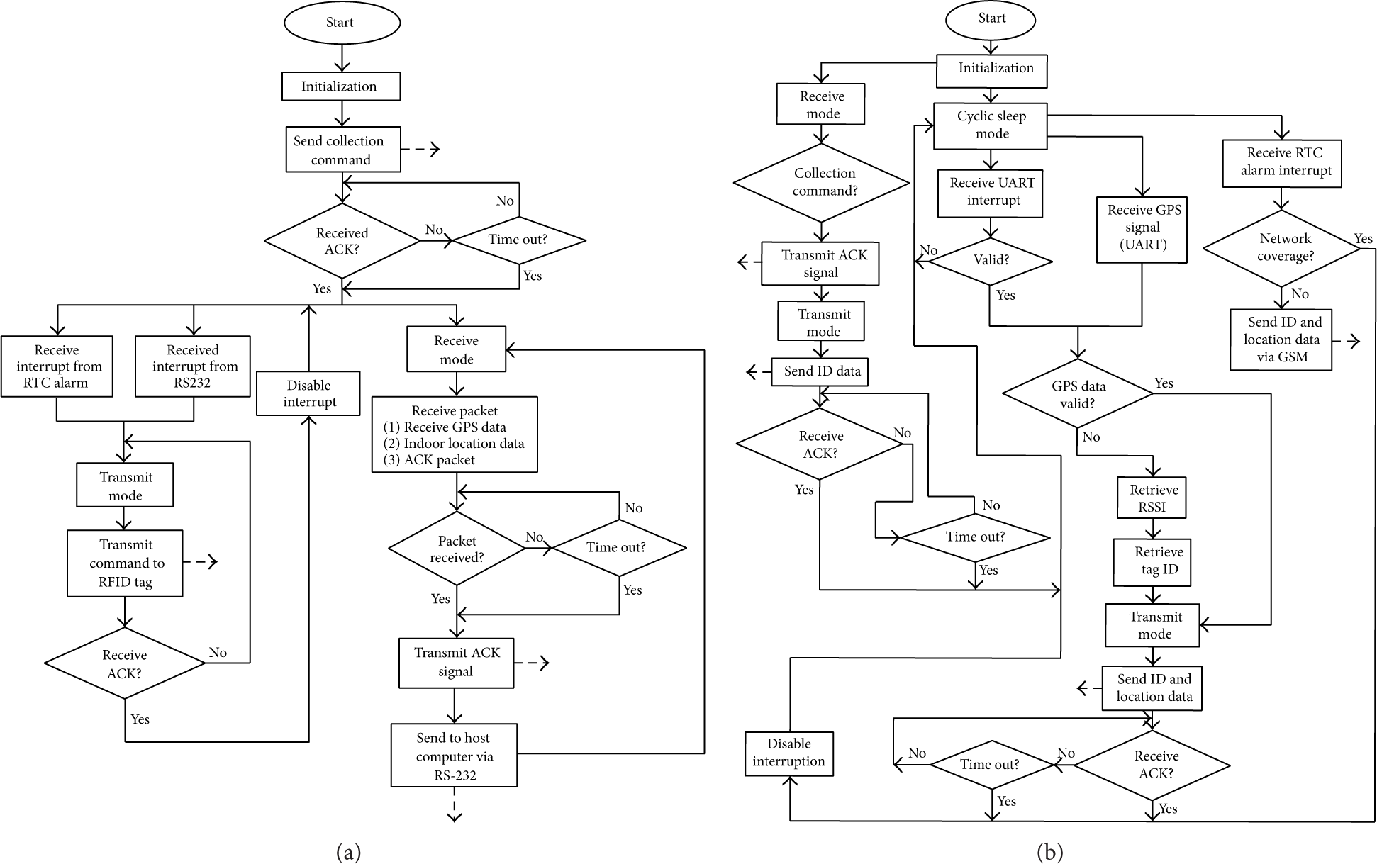
(a) The flow chart of algorithm implemented in the proposed RFID reader. (b) The flow chart of algorithm implemented in the proposed RFID tag.
4. Experimental Study for Propagation Analysis
There are four types of experiments conducted in an indoor environment with line of sight (LOS) direction. The first experiment is to measure the radiation pattern for both existing and proposed RFID system in order to evaluate the performance of the developed system based on automated switching algorithm presented. The second experiment is designed based on DOE method to identify the relationship, interactions, and effects of range, polarization, and angle of propagation based on RSS for both types of RFID system. The third experiment is to find the most significant power level that provides the best variation of RSS for the proposed RFID system to operate in certain range of indoor location. The fourth experiment is designed based on DOE method to investigate the interactions and effects between power level, range, and RSS for both existing and proposed RFID system. All experiments conducted in this work used the same experimental setup as shown in Figure 6. There are two test beds involved for all experiments. First test bed is for nonembedded RFID system (stand-alone system without GPS) which consists of existing RFID reader and RFID tag [19], while the second test bed is for the embedded RFID system which consists of a proposed active RFID reader and RFID tag embedded with GPS. The reader and tag are facing each other at a specific distance which later communicates in a single hop ZigBee network.
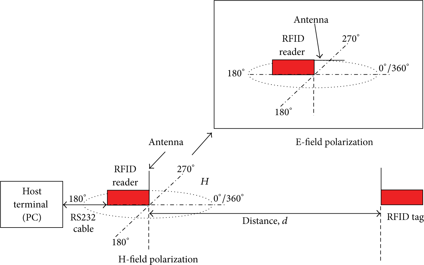
Illustration of polarization measurements.
4.1. Radiation Pattern Measurement
The radiation pattern measurements are done for both existing RFID system [19] and proposed RFID system to evaluate and compare the performance of the developed system based on automated switching algorithm presented at two different distances which are 2 m and 10 m. The far-field distance is obtained by using (1) [26] based on characteristic of the antenna used in this research work. Consider

Figures 7(a) and 7(b) show the comparison of radiation patterns of existing RFID system and proposed RFID system for H-plane polarization at 2 m and 10 m distances, respectively. The result for H-field radiation pattern at 2 m distance is an omnidirectional. It can be seen that the normalized radiation pattern for proposed RFID system is slightly better than the existing RFID system in between 90° and 195° degrees. However, the radiation pattern results for existing RFID system at 10 m distance are better than proposed RFID system by about 0.9 dBm to 6.4 dBm differences. The differences in antenna pattern may be due to the immediate surroundings since actual performance depends on many factors in the environment. Obstructions in the propagation path or other wireless networks or systems will also affect the performance. Figures 8(a) and 8(b) show the comparison of radiation patterns for E-plane polarization at 2 m and 10 m distances, respectively. The normalized radiation pattern for proposed RFID system is better than the existing RFID system at 2 m and 10 m distances. Based on these initial findings, it can be concluded that the radiation for shorter distance is stronger than longer distance in both H-plane and E-plane and the embedded mechanism for RFID system does affect the radiation pattern not more than 15% difference from existing RFID system. It shows that the proposed RFID system contributes to stronger radiation compared to existing RFID system. This may be due to the embedded power management that is implemented in the embedded active RFID tag that provided power stability as mentioned by [27] thus increasing the performance of the system in the network.
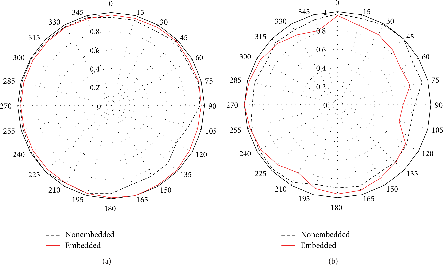
H-plane pattern at (a) 2 m and (b) 10 m distance.

E-plane pattern at (a) 2 m and (b) 10 m distance.
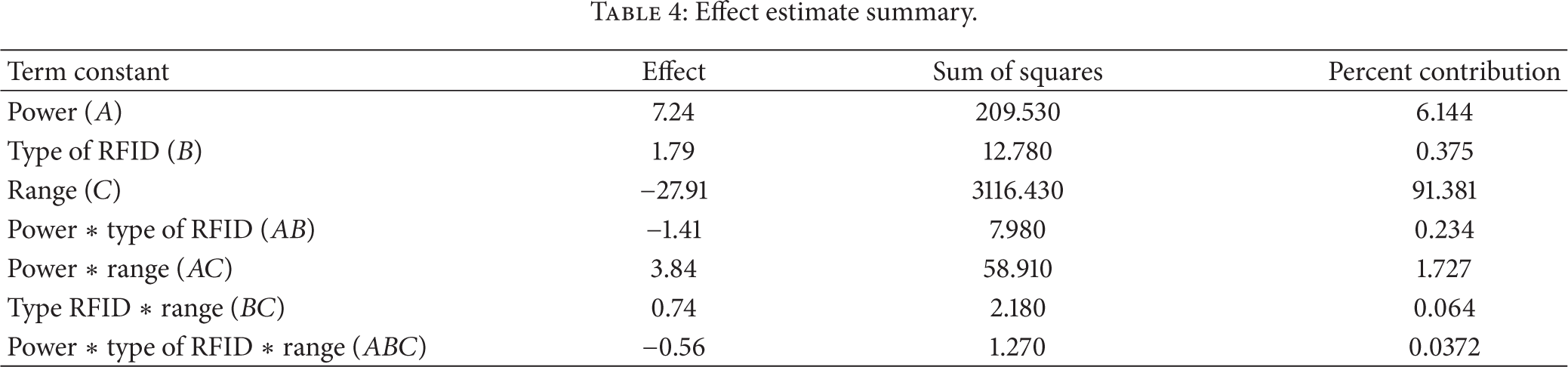
The second experiment is the continuity of the radiation pattern measurement which involved four factors with two levels of treatment, 24. The factors are referred to as type of RFID (nonembedded, embedded), power level (2 dBm, 10 dBm), range (5 m, 10 m), polarization (E, H), and angle of polarization (0°, 90°). The response of the experiment is in RSS and 2 replicates are used in this work to reduce the measurement errors and noise. The order in which the observations are taken is selected randomly so that the design is a completely randomized design. To identify the interactions and effects between type of RFID, range, polarization, and angle of propagation with RSS, a statistical method called analysis of variance (ANOVA) is used as presented in [28] and the effect estimate summaries for the proposed system are shown in Table 2.
Effect estimate summaries.

In this work, the main effect of A really dominates the process, accounting for 63.635 percent of the total variability, whereas the main effect of C accounts for about 7.328 percent, while the AB and BC interactions account for about 8.808 percent and 6.616 percent, respectively; thus it is proved that the RSS value can be used as a prediction method to measure distance and location of tags from reader in WSN platform since the range contributes highly significantly compared to other factors. The ANOVA in Table 3 is used to confirm the magnitude of these effects. From Table 3, it can be seen that the main effects of A and C are highly significant since both of the factors have very small P values (<0.001). For 4-way interaction, the ABCD interactions are also highly significant (low P values); thus it can be concluded that there is a strong interaction between four factors with RSS values.
ANOVA for the radiation pattern measurement.

Figures 9 and 10 show the interactions and main effects plot for radiation measurement that is used to interpret the results from Tables 1 and 2.

Interaction plot for radiation measurement.

Main effects plot for radiation measurement.
The graph shows that the RSS for existing RFID system is better than proposed RFID system at 10 m distance; however the RSS for proposed RFID system is better than the existing RFID system at 2 m distance. In terms of angle, the RSS for 0° and 90° degree proposed RFID system are better than existing RFID system; however the RSS value for 0° degrees is better than 90° degrees for both RFID system. In terms of polarization, the H-field polarization gives more significant values of RSS compared to E-field polarization for both RFID systems. The findings show that the RFID system will have better RSS value if it is located nearer to the reader at 0° degrees direction of propagation with H-field polarization of antenna. This statement is supported by Friis free space equation as shown in [26]


4.2. Power Level versus Range Measurement
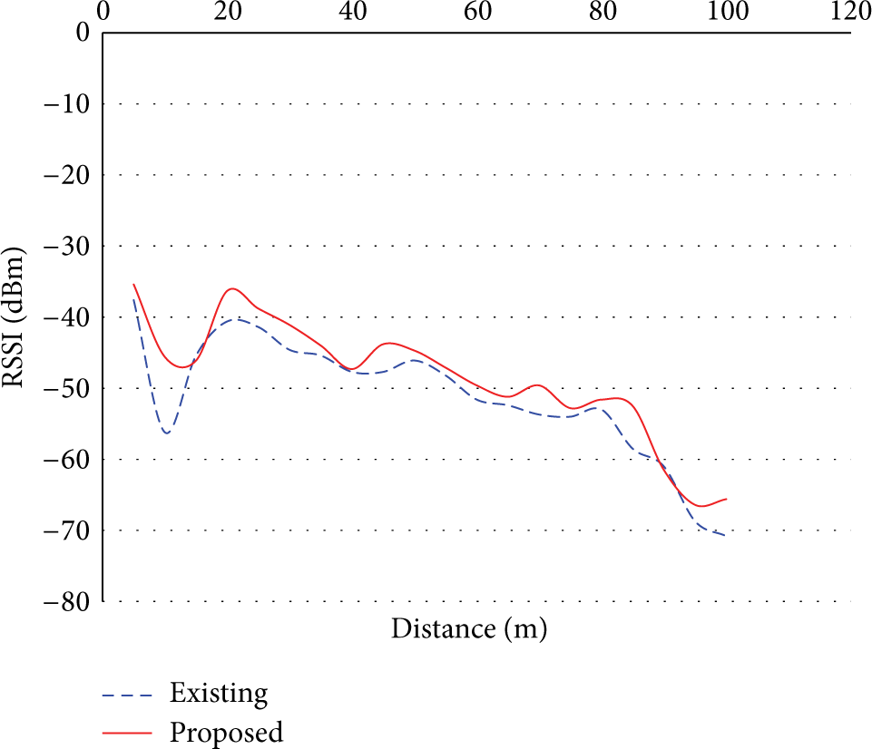
The power level versus range measurement is done for distance between 5 m and 100 m indoors with 5 m increment. The distance is limited due to the building's built-up area which is limited to 100-meter length. The response is RSS values which are measured for existing and proposed RFID system at two levels of power which are 10 dBm (max) and 2 dBm (min). At each point, 10 single values of receiving power are collected to calculate the mean. Figures 11 and 12 show the comparison between RSS values of existing and proposed RFID system based on distance of 5 meters to 100 meters indoors at 10 dBm and 2 dBm power levels. The graph shows that the RSS values are decreased when the distance is increased at both power levels. The existing RFID system gives better RSS values than proposed RFID system at 10 dBm power level while the proposed RFID system gives better RSS values than existing RFID system at 2 dBm power level. To compare the performance of two types of RFID system based on power level and range, the third experiment is conducted based on DOE method with three factors having two levels of treatment, 23. The factors are referred to as type of RFID (nonembedded, embedded), power level (2 dBm, 10 dBm), and range (5 m, 10 m). The response of the experiment is RSS and 2 replicates are used in this work to reduce the measurement errors and noise. The order in which the observations are taken is selected randomly so that the design is a completely randomized design. Later, the statistical method ANOVA is performed using Minitab 16.2 and the results are displayed in Tables 4 and 5 for effect estimate summary and ANOVA for power level versus range measurement. From the effect estimate summary presented in Table 4, the main effect of C really dominates the process, accounting for 91.381 percent of the total variability, whereas the main effect of A and the AC interaction account for about 6.144 and 1.727 percent, respectively; thus the DOE for this experiment also proved that the RSS value can be used as a prediction method to measure distance and location of tags from reader in wireless sensor network platform since the range contributions are highly significant compared to other factors. The ANOVA in Table 4 is used to confirm the magnitude of these effects. From Table 5, the main effects of A, B, and C are highly significant since the factors have very small P values (<0.001). For 2-way interaction, the AB and AC interaction are also highly significant (low P values); thus it can be concluded that there is a strong interaction between two factors with RSS values in this experimental study. Figures 13 and 14 show the interaction and effects plot for power level versus range measurement that is used to interpret the results from Tables 4 and 5. It can be seen that the RSS for embedded RFID system is nearly equal to nonembedded RFID system at 10 dBm power level. However, at 2 dBm power level the RSS for embedded RFID system is better than nonembedded RFID system. In terms of range, the RSS for embedded RFID system is better compared to nonembedded RFID system at both 5-meter and 100-meter range. Based on the results obtained, it can be summarized that for indoor tracking purposes the low power level gives better RSS values for embedded RFID system compared to nonembedded RFID system. This finding can be supported by [29] which stated that the low transmit power is appropriate and sufficient for area with limited range; however if the high transmit power is use in the area with limited range, it will resulting in disturbance that will cause degradation in radiation performance. Thus to design an efficient indoor localization system, these findings must be taken into account as a guideline implementing the full setup for real time location monitoring system in WSN platform.
Effect estimate summary.
ANOVA for power level versus range measurement.


Received signal strength values at 10 dBm in an indoor environment.
Received signal strength values at 2 dBm in an indoor environment.

Interaction plot for power level versus range measurement.
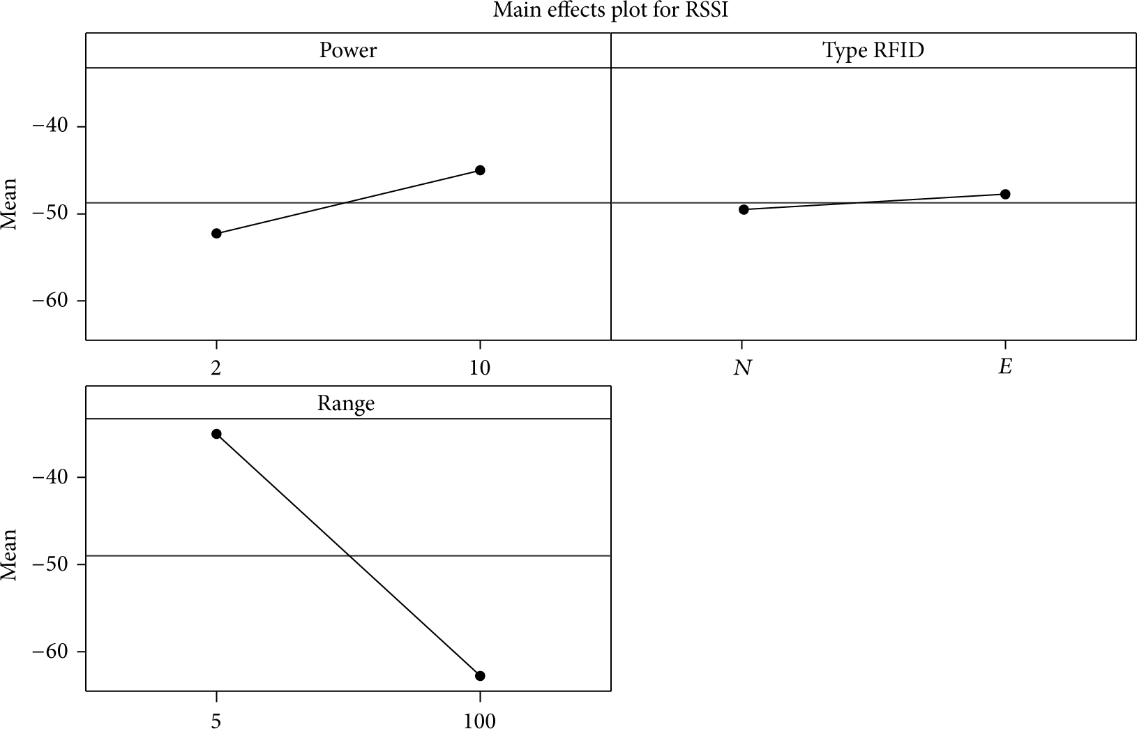
Main effects plot for power level versus range measurement.
5. Battery Life Testing
A single RFID tag requires a minimum of 2.7 V to 3.3 V voltage to operate as a transmitter and receiver in the network. Howver, the embedded RFID tag proposed in this work requires minimum of 5.0 V to power up the embedded devices. Thus, the embedded RFID tag can be powered up using 9 VDC power supply if the tag is located at fixed location or Li-Po rechargeable batteries can be used if the tag is mobile. The tag has been programmed to consume the lowest amount of energy as much as possible since it introduced an automated switching mechanism between indoor and outdoor location tracking and operating in sleep mode at certain time. The RFID tag only sends data if the valid outdoor location is detected by the GPS receiver; however if the embedded RFID tag is located inside the building or the place where the signal from satellite cannot be detected by the GPS receiver, it will turn to sleep mode and wait for the RFID reader interrogation every hour. The GSM modem only works when the embedded RFID tag is out of the wireless network coverage to consume the lowest amount of energy.
The battery lifetime measurement is performed for three systems which are stand-alone RFID tag (A) [20], embedded RFID tag with switching mechanism (B), and embedded RFID tag without switching mechanism (C) in an indoor environment (inside building) where the GPS signals are not available most of the time. The results show that the battery for the tag drops from 8.24 V to 7.11 V in the duration of 8.5 hours for the proposed embedded RFID tag with switching mechanism compared to other systems as shown in Figure 15.
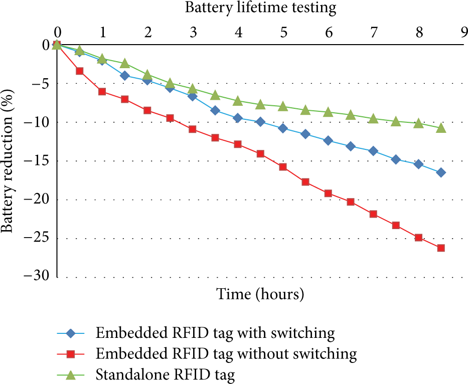
Battery life testing based on three types of RFID designed.
The results for system B are much better than system C due to the switching introduced. However the result for system A is better than system B due to the nonembedded system. According to these real implementation results, the tag will be expected to stop operating approximately in 24 hours when the battery reaches the minimum voltage required, which is 5.0 V. However, this result does not include the situation where the proposed embedded RFID tag is located outside building which might increase the energy usage. The estimation results also did not include other external factors that might reduce the battery life. Thus the tag is estimated to cover the operation for a day without having to recharge the battery until the next day. To reduce the energy consumption and maximize the time of usage, an energy harvesting technology will be implemented later in the embedded RFID tag as our next target.
6. Conclusion
This paper describes the implementation of an automated switching algorithm in the design of a 2.45 GHz active integrated RFID system for indoor and outdoor location tracking utilizing WSN platform. Four experimental measurements based on DOE method are performed in order to validate the performance of the proposed RFID system as well as to study the relationship, interaction, and effects of each factor to RSS values extracted from existing and proposed RFID system. The results obtained from first experiment show that embedded RFID system does affect the radiation pattern, not more than 15% differences from existing RFID system. It shows that the proposed RFID system contributes to stronger radiation compared to existing RFID system. This may be due to the embedded design and improvement of algorithm implemented in the proposed RFID system, which increased the power stability of the system which thus provided higher signal strength [28].
In the second experiment, the results show that the proposed RFID tag has better RSS value when it is located nearer to the reader at 0° degrees direction of propagation with H-field polarization of antenna. In the third experiment, the existing RFID system gives better RSS values than proposed RFID system at 10 dBm power level while the proposed RFID system gives better RSS values than existing RFID system at 2 dBm power level. In the fourth experiment, it can be summarized that for indoor tracking purposes the low power level gives better RSS values for the proposed RFID tag compared to the existing RFID system. The statistical analysis ANOVA proved that the RSS values are significant with range; thus it can be concluded that the RSS can be used as a prediction method to evaluate distance between RFID reader and RFID tag in WSN platform. Based on the experimental study and statistical analysis done for all situations, a conclusion has been made where the proposed RFID system with automated switching algorithm is better than the existing RFID system in terms of performance and variability of the factors. The battery life testing also gives significant findings where the proposed embedded RFID tag with switching mechanism introduced is much better than embedded RFID tag without switching mechanism. To increase the performance of the embedded RFID tag in terms of time of usage, an energy harvesting technology will be introduced later as a part of our next contribution. In terms of hardware costing, the proposed approach is more acceptable compared to the system developed by [6] since the technology used in this work especially GSM communication is much cheaper than satellite communication used in the existing system [6]. In addition, this proposed system does not totally depend on GSM since the communication will be done by RFID which is free as long as the embedded RFID tag is working in the control area of WSN platform. However the existing work [6] did not support long range communication and thus when the tag is moving far from the reader, the satellite communication needs to be used and this will lead to high cost of communication. As a conclusion, the proposed embedded RFID tag provided better signal propagation compared to the existing RFID tag [19] and the battery lifetime for embedded RFID tag with switching mechanism is better than that without switching mechanism.
Footnotes
Conflict of Interests
The authors declare that there is no conflict of interests regarding the publication of this paper.
Acknowledgments
The authors would like to thank Malaysia Ministry of Higher Education (LRGS Fund) for sponsoring the research and developing this project. Also, special appreciation is due to Professor Dr. Mohamad Kamal Abdul Rahim from Universiti Teknologi Malaysia, Head of the LRGS Project, and Associate Professor Dr. Alyani Ismail, Universiti Putra Malaysia, for the support.