
Abstract
In Underwater Acoustic Sensor Networks (UW-ASNs), some key problems have attracted more and more attention, including power consumption, performance of multiple access, and complexity of node. Motivated by finding reduced power consumption and improved performance of multiple access in UW-ASNs, a multilinear chirp-Code Division Multiple Access (MLC-CDMA) scheme is proposed. The differences between single slope chirp signal and multilinear chirp signal are analyzed in the paper. At the receiving end, a new detection technique called mixing-change rate along with fractional Fourier transform (MCR-FrFT) is proposed to detect the multirate chirp (MRC) signal and reduce complexity of node. There are two steps to realize the detection technique MCR-FrFT. By using the MCR-FrFT, the computation of detection can be decreased to 50% compared with direct FrFT. The simulation results indicate that, using the MCR-FrFT technique, the different users' signal can be separated and detected rapidly.
1. Introduction
Underwater Acoustic Sensor Networks (UW-ASNs) call for deployment of multiple autonomous underwater units or sensors can be used for a wide range of marine applications, including oceanography, environment monitoring, undersea exploration, mine reconnaissance, disaster prevention, tsunami warning, equipment monitoring, military oversight, and navigation [1–6]. These nodes are manually or randomly scattered in different depths in underwater environments to collect specific data from deep or shallow water [7]. To enable their collaborative operation in a shared physical channel, multiple access communications must be established [6]. Code Division Multiple Access (CDMA) is the most promising physical layer and multiple access technique for UW-ASNs [1]. As with other spread spectrum methods, chirp spread spectrum uses its entire allocated bandwidth to broadcast a signal, making it robust to channel noise. Further, because the chirps utilize a broad band of the spectrum, chirp spread spectrum is also resistant to multipath fading even when operating at very low power [6]. Additionally, chirp signal and a low Doppler sensitive signal have also been used in underwater wireless communication (UWC) [5]. With the help of multilinear chirp (MLC) signals used in terrestrial sensor networks and because chirp signal modulation technique has been used widely in underwater acoustic communication [8], the MLC-CDMA scheme is proposed for UW-ASNs in the paper.
The technology of multiple access using chirp signals were first referred by Cook [9]. MAI mitigation methods used in common CDMA system can be directly used in this chirp CDMA, while using frequency-shift keying (FSK) may cause undesirable MAI [10]. However, there are some disadvantages of this method. The data rate is limited by the total length of spreading codes, the bandwidth efficiency is low especially for single slope chirp- (LFM-) CDMA [6], and the performance of multiple access is not efficient. In [11–13], multilinear chirp (MLC) signals are used in multiple access technique CDMA. Since these signals can be occupying the same bandwidth, this method is bandwidth efficient [10]. And the differences between traditional chirp signals (LFM) and MLC are analyzed in this paper, including the performance of multiple access. On the other hand, neither simple nor feasible detection method is mentioned in previous papers. In order to make the system more feasible and effective, a novel detection method called MRC-FrFT (multirate change-fractional Fourier transform) is proposed in the paper too.
There are some methods to estimate the parameter of chirp signal. In [14], the method of time-delay frequency mixing (rate reduction) to convert the chirp signal with different chirp rate into MFSK signal is mentioned. In [15], authors present dechirp pulse compression processing technique. The two methods are effective to single slop chirp signal but unsuitable for MLC signals due to numbers of multipliers and no fixed chirp rate. In [12, 16], matched filter receivers are used, and at least 2M-filters are needed (M is the user number). It adds the complexity and power consumption of node. What is more, it is difficult to achieve. In very simple terms, the fractional Fourier transform (FrFT) is a generalization of the ordinary Fourier transform. Specially, the FrFT implements the so-called order parameter p which acts on the ordinary Fourier transform operator [17]. In other words, the pth order FrFT represents the pth power of the ordinary Fourier transform operator. The FrFT presents the best localization performance in a certain FrFT domain, which is fit for the detection and estimation of multicomponent linear frequency modulation (LFM) signals [18–20], and some fundamental properties of fractional Fourier transform can be found in [21]. Some improved algorithms based on FrFT are also proposed, such as EEMD-FRFT [22] and STFT [23], but these methods need 2 different p values to complete the parameter estimation. So for MLC signal, the main drawback of FrFT is heavy computation. To solve these drawbacks, MCR-FrFT is proposed in the paper. The system used in underwater acoustic channel [24] is discussed too, and it shows that the system can be used in underwater acoustic channel normally. The contribution of our work can be divided into three parts: proposing MLC-CDMA system in UW-ASNs, comparing the difference of multiple access performance between single slope chirp and MLC signal, proposing MCR-FrFT to reduce the complexity and computation of the system.
The remainder of this paper is organized as follows. Section 2 introduces the related work and the signals designed for different nodes in UW-ASNs. Section 3 describes the new detection technique of MCR-FrFT. Section 4 analyses the performance of MCR-FrFT with different kinds of received signals, and in Section 5 the simulation results are shown. Finally, in Section 6, we draw the conclusions.
2. Chirp Signal Model
Single slope chirp (LFM) signals are used in UW-ASNs for node localization in our research group. And the multiple access technology using single slope chirp signals is being studied in our group too. Our work indicates that the demodulation is quite complicated when there is not only one node signal received at the same time. One of the reasons is the unfairness between users caused by different time-bandwidth products, and the multiple access using single slope chirp signal is not effective. Based on our work and paper [10, 11], to overcome the deficiency above, we choose the MLC signals instead, where time-frequency characteristic is as shown in Figure 1(b).

The difference in time-frequency characteristic between LFM signals and MLC signals. (a) Time-frequency graph for LFM signals. (b) Time-frequency graph for MLC signals.
Figure 1(a) is the time-frequency characteristic of LFM signals, while Figure 1(b) is the time-frequency characteristic of MLC signals.
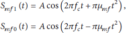
For LFM signals, the mth user's signal could be expressed as


The subscripts “1” and “0” mean bit 1 and bit 0. The subscripts “f” and “b” indicate the first half and second half of the duration of one bit signal. And


The time-bandwidth product
The performance of multilinear chirp is mainly determined by the cross-coherence between the different node signals. Ideally the signals should be orthogonal with zero cross-coherence to cancel the multiple access interference (MAI). The biggest cross-coherence coefficient existed in adjacent node and adjacent signal.
Set

Substituting the corresponding values of

Taking

From (9), ρ has an oscillatory nature as a function of time. Set

The cross-coherence function ρ. (a) As a function of time with
The difference between single slope chirp signal and MLC signal in cross-coherence is shown in Figure 2(a). The empty circle (o) is the cross-coherence coefficient of MLC signal, and the solid dot (·) is the cross-coherence coefficient of single slope chirp signal. From Figure 2(a), when there is the same number of nodes in the UW-ASNs, such as 15, the performance of multiple access using MLC signals is better than the one using single slop chirp signal. For example, when the duration time is 0.01 and that time product is 100, the cross-coherence coefficient of single slop chirp signal is about 0.1 bigger than MLC signal. The time-bandwidth product is 100 in Figure 2(b); here the cross-coherence as a function of node number that is the performance of multiple access changed depend on the number of nodes. At the same time, Figure 2(b) tells us that the performance of multiple access using MLC signal is much better when the number of nodes is the same. So the MLC signals are selected in the paper for chirp-CDMA. And in the next section, the detection method for this kind of MLC signal is described.
3. The Detection Block Diagram
The detection technique MCR-FrFT and its block diagram are shown in Figure 3. The received signal is divided into three branches after mixing with PN Code. The first branch and third branch use fixed local signal,

Receiver block diagram for MLC-CDMA.
3.1. Mixing-Change-Rate (MCR)
The purpose of MCR is to change the set of chirp rates of MLC signal into a new set. It includes two parts, multiplier and low pass filter. The block diagram of MCR is shown in Figure 4.

The block diagram of MCR.
That is,

Consider
3.2. Fractional Fourier Transform (FrFT)
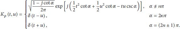
FrFT, which can be expressed as rotating the signal an angle of α to u-axis anticlockwise on the time axis, is a generalized Fourier transformation form and is the linear projection of the signal to the rotary frequency space. The FrFT definition of signal

And the transformation kernel is
Simple component LFM signal with noise is

where

where
From (14), one LFM signal is an impulse function only in the appropriate fractional Fourier domain. Select the right angle of rotation (or p value) to do FrFT for LFM signal, then the amplitude of energy aggregation of LFM signal will show obvious peak. The energy of noise, which cannot show energy aggregation at any fractional Fourier domain and cannot show the peak, distributes on the whole time-frequency plane evenly.
4. The MCR-FrFT for Different Received Signals
In this section, different received signals have been discussed, such as single user's signal and three users' signal. There are two levels of MCR-FrFT at the receiving end. The first level uses the local signal to convert the chirp rates of MLC signal into a new set of chirp rates. The second level adopts the FrFT to estimate the parameter.
4.1. Single Node Signal
Assuming that only the mth node's signal is received, substituting the corresponding value of

Comparing the third branch and the first branch in (16), after MCR, the MLC signal composed of two positive slopes in the third branch is just only a short time duration (less than 1/6 duration time), as shown in Figure 5(b). So the MLC signals for bit “1” can be ignored in the third branch; similarly, the MLC signal composed of two different negative slopes for bit “0” in the first branch can be ignored too.

(a) The new sets of chirp rate by MCR. (b) Show the difference of chirp rates after MCR between the first branch and the third branch with the frequency within about
Substituting the corresponding values μ of (5) and (10) into (16), neglecting the third branch, we get

The
Figure 5(a) is the original MLC with two positive slopes, and after MCR, the slopes are changed as shown in Figure 5(b). At the corresponding branch, we get a new MLC signal with the set of chirp rates, where the two values are opposite, as dashed line shows in Figure 5(b). The solid line in Figure 5(b) is the MCR result at the other branch (no middle branch).
According to Section 3.2, the parameter estimation based on FrFT is not sensitive to noise, and the result mainly depends on the signal. Figure 5 shows that, using the MCR, the set of chirp rates is changed from two different slopes (Figure 5(a)) to a new set of chirp rates, where two slopes are opposite. With the fundamental property of FrFT and DFrFT mentioned in [17] that only one p value is needed to complete the new MLC signal with two slopes opposite while the original MLC signal needs two different p values to complete its parameter estimation, the computation using MCR-FrFT can almost be reduced to 50% compared with direct FrFT without MCR.
4.2. Multipath Underwater Channel
The impulse response of an underwater acoustic channel is influenced by the geometry of the channel and its reflection properties, which determine the number of significant propagation paths, their relative strengths, and delays. Strictly speaking, there are infinitely many signal echoes, but those that have undergone multiple reflections and lost much of the energy can be discarded, leaving only a finite number of significant paths. At this point, the channel impulse response can be expressed as

Assuming that the emission signal is

Take the mth node as an example, and set

After MCR, we get

The signals of different nodes are detected according to the different sets of chirp rates, and (21) shows that the multipath and noise of underwater channel do not change the chirp rate or generate any new chirp rate compared with (17). For fixed M, T, and B, the chirp rates are only determined by m. So the detection result will not be affected by multipath underwater acoustic channel.
4.3. Multiple Users' Signal
From Sections 4.1 and 4.2, we can see that the noise of underwater channel does not change the chirp rate, so it can be ignored temporarily in the process of analysis. When there is not only one MLC signal received, assume that there are three MLC signals received: user 1 bit “1,” user 2 bit “1,” and user 3 bit “0.” Here, two cases are considered: the first one is that all these signals are received at the same time and the other one is that these signals are not received at the same time.
If these signals are received at the same time, substituting the corresponding values of

According to (23), the new sets of chirp rates can be shown in Figure 6(b).

The sets of chirp rates of MLC signal received at the same time. (a) The original slopes of three MLC signals. (b) The new sets of chirp rates after MCR.
The solid line in Figure 6(b) is the MCR result of the solid line in Figure 6(a) in time-frequency characteristic at the third branch while the dot line and circle line are at the first branch.
Above all, taking bit “1” as an example, the MLC signals' rates changed by MCR can be expressed as

Substituting the corresponding values of μ in (3) and
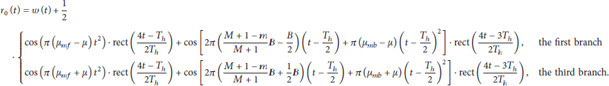
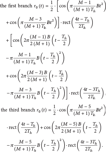
If these signals are not received at the same time, there is relative time-delay between one another; substituting the corresponding values of


Assuming that

The signals of user 1, user 2, and user 3 for bit “1” are not received at the same time. (a) The slopes of MLC signals. (b) The slopes after MCR corresponding to (a).
In Figure 7(b), the dots are the received signal without time-delay, the empty circle is the received signal where the time-delay is less than half of the per bit signal duration, and the solid line is the one where the time-delay is bigger than half of per bit signal duration but less than per bit signal duration.
From the above, the result of MCR of MLC signal is also a MLC signal but the new set of chirp rates is composed of two opposite slope values.
Since the inverse of an FrFT with an angle α is the FrFT with an angle
5. Simulation
The simulation tool MATLAB is used to evaluate the performance of MCR-FrFT. Set the total number of nodes

(a) The waveform of received signal. (b) The result of detection.
Figure 8(a) is the waveform of received signal including only one MLC signal at the SNR that is 0-dB. Figure 8(b) indicates that, using the MCR, the parameter of MLC signal can be detected correctly with the SNR that is 0-dB for AWGN channel. Of course, M times FrFT with different p values have been taken at the first and the third branches, respectively, but only when
In the condition of Section 4.3 the waveform of

(a) The waveform of received signal. (b) and (c) are the result of MCR-FrFT.
From (27), set the time-delay between the first node and the second node that is

(a) The waveform of received signal. (b) The result of its FrFT.
For Section 4.2, set

(a) The waveform of received signal. (b) The result of its MCR-FrFT result.
According to Figure 11(b) and the value of T and τ, those signals where the time-delay is smaller than
According to [13], the relationship between bit error rate (BER) and cross-coherence coefficient of single slope chirp signal or MLC signal can be expressed as


BER for (a) LFM and MLC signals. (b) FSK and MLC FH-CDMA techniques for an AWGN channel.
It can be seen from Figure 12(a) that the BER performance of the MLC signals is better than the single slope chirp signals. The reason is that the cross-coherence coefficient of single slope chirp signals is bigger than the one of MLC signals. And the BER is a monotone decreasing function as cross-coherence coefficient. Figure 12(b) shows the performance comparison of the MLC and FSK FH-CDMA, and the MLC scheme always outperforms the FSK scheme. For example, for 8 users and
6. Conclusions
Code Division Multiple Access (CDMA) is the most promising physical layer and multiple access technique for UW-ASNs. Since the chirp spread spectrum is resistant to multipath fading and is of low Doppler sensitivity, it is used in UW-ASNs widely. And the technology of multiple access using chirp signals was referred to. To improve the performance of multipath access, a new scheme with MLC signal has been proposed in terrestrial sensor networks but not in UW-ASNs. In this paper, the scheme of multilinear chirp-CDMA (MLC-CDMA) used in UW-ASNs is proposed; the comparison of LFM (linear chirp signal) and MLC signals shows that MLC is a better choice. And MCR-FrFT, a detection technique for MLC-CDMA, is proposed too. The MCR-FrFT is a receiver-based scheme, which reduces both the complexity and the computations of the system. The simulation results show that our MLC-CDMA system with MCR-FrFT signal detection technique achieves higher performance of multiple access in UW-ASNs than FSK-CDMA. Further, maybe we can use the detection technique to estimate the time-delay and use it in the location system.
Footnotes
Conflict of Interests
The authors declare no conflict of interests.
Acknowledgments
This work was supported by the Nation Natural Science Foundation of China (61471308, 61001142, and 61301097) and the Fundamental Research Funds for the Central Universities (2013121023).