
Abstract
We present an approach for the modelling and simulating of the modem section of underwater sensor networks. The proposal is based on a specially designed modem architecture and the use of simulation tools and models that represent each of the communication elements: the water medium, physical transducers, electronics, and coding/decoding software. The algorithms can be simulated in the modelling environment; this framework does not require recoding and allows the combination of real and modelled elements. In physical terms, the modem engine provides a decoupled pipelined design of the processing path for the algorithms which allows users to run complex algorithms without requiring a highly demanding specific hardware. The proposal includes a methodology that has allowed us to significantly reduce the effort required in the process, from algorithm development to the effective deployment of the system. As a case study, this paper shows its application and results in the evaluation of a multipath and Doppler-shift correction algorithms.
1. Introduction
Underwater wireless sensor networks (UWSNs) are a fast growing technology focused on the analysis of underwater phenomena which includes water monitoring, disaster prevention, navigation assistance, and fish production monitoring. It can be stated that its goals are similar to those of its terrestrial counterparts yet presenting challenging problems which need to be addressed by researchers.
An active research area in UWSNs is the inescapable need for communication between nodes. When compared with their terrestrial counterparts, underwater communications technology is still at an immature stage of development. As a physical medium, water differs from air; electromagnetic waves are atenuated by water which limits their use. At the moment, the most reliable transmission technique for medium and long range underwater communications is based on acoustic signals.
Compared with electromagnetic transmission, the behaviour of acoustic waves in the underwater medium presents different signal attenuations depending on distance and frequency. In addition, signal spreading is proportional to distance due to expansion of wave-fronts. Signal propagation speed is 1500 m/s, five orders of magnitude lower than in electromagnetic transmission, which makes it an important factor to be considered. This propagation speed is modified by variations in temperature and salinity and the movement of water, which produces a noticeable Doppler effect. As in electromagnetic transmission, there are similar noise and reflection problems that are more evident in offshore waters which are often chosen for the deployment of UWSNs.
Given these medium-dependent problems, it is difficult to provide a universal communication node that provides long battery life and excellent communications performance. If we need, for example, a maintenance-free long life node, then the node could be built around an ultralow power microcontroller at the expense of poor communication speed and flexibility. If we need, for example, to deal with complex scenarios requiring fast communications, then a possible solution would include the use of DSP or FPGA nodes which use substantial amounts of energy.
Our initial efforts were focused on the development of an ultralow power node, which led to the design, construction, and deployment of the ITACA modem [1]. We were able to develop an excellent solution with long node life but with some scalability issues, making it unfeasible for our new oceanographic projects which require greater scalability and flexibility.
Given these issues, we decided to focus our research work on the design of an appropriate modelling methodology that could help develop generic, scalable, and flexible solutions.
The resulting proposal combines specially designed modem architecture, a set of simulation tools, a combination of real and synthetic communication traces, and a workflow that dramatically reduces the time and effort gap between an algorithm proposal and its effective deployment. Compared with other approaches, this approach avoids the interdependence between different areas of development (algorithms, hardware, medium, etc.) so the work on one aspect does not block other lines of work. Also it is focused on ultralow power designs thanks to the specially designed architecture.
Thanks to the modelling proposal, we can easily change any hardware component or algorithm and reevaluate it.
This paper will describe this modelling methodology and illustrate its application to a successful case study presented in [2]. In Section 2 the state-of-the-art in underwater wireless sensor network research is presented. Section 3 explains the proposed framework, including the design workflow. Section 4 describes the proposed modem architecture. Section 5 is a case study applying the proposed methodology showing the obtained results. The conclusions are presented in Section 6 of the paper.
2. Related Work
Currently, there are some acoustic modems in production and available for purchase. Companies include LinkQuest [3], Teledyne Benthos [4], TriTech International [5], Aquatec Group [6], EvoLogics [7], and DSPComm [8]. In addition, there is the open architecture Micro-Modem developed at Woods Hole Oceanographic Institute (WHOI) [9]. However the high cost of the modem (some thousands of dollars) and high power consumption (typical: 0.7–0.8 W in receiving mode, 2 W to 84 W in transmission) make it difficult to develop affordable underwater sensor networks.
Extensive research is currently being conducted at several universities around the world to develop new modems that make real network deployment feasible. The most promising modems have been developed at the following universities: South California [10], California Irvine [11], California Santa Barbara [12], Connecticut [13], and the Massachusetts Institute of Technology [14, 15]. However, although some solutions are relatively inexpensive (below 100$ in some cases [16]), power consumption is still high compared to recent advances in wireless sensor networks [17].
In [1] a completely new approach is explored: a generic architecture based on modern ultralow power microcontrollers that can be extended with specific hardware units to perform certain tasks. The result is a 1000 kbps modem with power consumption below 10 μW in standby mode. The modem includes a state-of-the-art acoustic triggered asynchronous wake-up system [18] that allows ultralow power MAC protocol designs [19, 20].
There are many simulation tools that define different models of underwater acoustic signal propagation; indeed there are almost as many simulation tools for this purpose as there are MAC and routing protocols [21]. Models range from simple ones, based on the Thorp equation [22], to complex ray tracing models such as Bellhop [23] which are used in different tools to simulate networks and protocols. It is hard to compare two different models unless they are implemented on the same platform, and, even in this case, the simulator should be as realistic as possible when simulating real environment conditions; otherwise the results will lack accuracy; these still require empirical testing, at least in scale-down experiments, before releasing the final implementation of the underwater nodes. These constrains reduce the power of simulation tools to predict real network behaviour [21].
To address simulation inaccuracies, a number of studies are moving towards platforms to facilitate UWSNs experiments [24–28]. Experiments on these platforms are limited to high level protocol layer evaluation (MAC, Network, Application, etc.). Lower layers are implemented using existing commercial modems that cannot be reconfigured out of the predefined modem settings.
Integration of previous approaches (accurate simulation and reconfigurable real deployment) would lead to an innovative framework for development of reliable UWSNs. A newly combined framework would allow for significantly faster experimentation, evaluation, and validation. However, as far as we know, this framework still does not exist.
3. IUmote Framework
3.1. Modelling Approach
Figure 1 shows a block diagram of the proposed modelling framework. The framework combines the use of numerical analysis software, simulation models, hardware testbed prototypes, and a specially designed modem architecture.
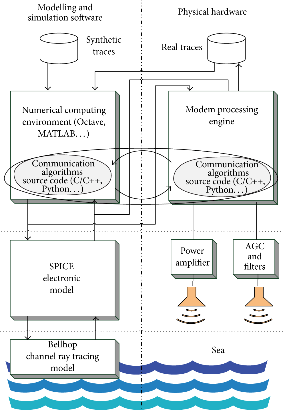
IUmote framework diagram block.
The right side of the diagram represents physical components that make up the modem of an underwater node.
The left side of the diagram shows numerical analysis software and simulation models and tools. For each physical element on the right side there is a corresponding block on the left side. The modules are organized in layers and can be moved virtually from right to left in the work flow that will be presented in Section 3.2.
At the bottom of the diagram is the underwater physical medium, which is the communication channel. It is modelled using the Bellhop [23] ray tracing model. There are implementations of this model for numerical analysis software such as Octave or MATLAB or for network simulators such as ns-3 [29] or opnet [30]. In our case, we have used ns-3 to model the water communication channel [21, 31] where we describe the real conditions under which our UWSNs installation will be deployed.
The next layer contains physical piezotransducers associated with power amplifier electronics for generating sound waves and piezotransducers/hydrophones and their corresponding signal filters and automatic gain circuits for receiving sound. These blocks are modelled using SPICE [32].
In the upper layer we have the computing engine. On the right side it has a microcontroller-based modem architecture that will be described in Section 3 and, on the left side, it is modelled by a numerical analysis software, which is Octave in our implementation.
Communication algorithms can be implemented either in the programming language of the analysis software or in the native language of the processing modem (usually in C/C++ language). In early design stages the higher level language of the analysis software allows for fast prototyping, while final testing algorithms written in the native implementation of algorithms avoid translation mistakes and, thus, enhance reliability.
The data input for the numerical analysis software can either be synthetic traces or real recordings obtained at sea using this infrastructure. Figure 5 shows a synthetic trace sample and its equivalent obtained in water.
The generated sound wave for communications can be redirected from the numerical analysis software to the modem or from the modem to the numerical analysis software when we design a campaign at sea. This mixture of relationships between blocks saves time as sea campaigns enable collecting communication traces for later analysis.
3.2. Workflow
The modelling approach is part of a workflow methodology that is explained in this section. Figure 2 shows a digram of this workflow.

Diagram of the workflow methodology.
The workflow is a closed loop, which can be started in any of the stages assuming there is sufficient past material which can be used to progress through the workflow. For the purpose of explanation we will start in the “proposal” stage. The main stages are described as follows: The “proposal” stage is where a new algorithm or hardware is proposed. In the “implementation” stage, the proposed algorithm o hardware can be developed virtually as a SPICE simulation model or a numerical program, or a real implementation can be developed in the form of a native C/C++ algorithm or a real hardware device that is added to the framework. In the “simulation” stage, the behaviour of the proposed algorithm or hardware can be evaluated using synthetic traces or real traces obtained from sea campaigns or our water tank. In the “real testbed” algorithms and hardware are tested using either the software running under the numerical analysis software or a real implementation running in the modem processor. This stage needs a real water medium either the laboratory water tank or the sea campaigns. During this stage, the sound traces used in other stages are recorded. In the “results analysis” stage, the output of simulations or the real traces are analysed and/or used to run new simulation tests.
Synthetic traces are based on noise models, Doppler effect distortion, and multipath reflections. They can be tuned by mixing previously collected real noise or human-produced sounds such as sonar signals. They represent the best choice in the early stages of algorithm or hardware development.
4. Modem Processing Engine
A modem architecture has been designed to fit this methodology, providing a highly flexible, low power solution which at the same time is able to run very complex processing algorithms without requiring specialized hardware such as DSPs of FPGAs. Figure 3 shows a block diagram of the modem architecture.

IUmote modem implementation diagram block.
The processing engine is an STM32F4x series microcontroller from Stmicroelectronics. This microcontroller is based on ARM Cortex-M4 architecture and provides a rich set of peripherals, a peak speed of 168 MHz, and a hardware-based simple precision floating-point unit.
Software for the processing engine is based on the CheapDAQ [33] open source project. This project is devoted to the implementation of microcontroller-based data acquisition systems and its main objective is to create abstractions of the underlying hardware in order to facilitate the creation of both master-slave and stand-alone systems. This simplifies the effort needed to develop software that can run on both the modelling platform and the modem engine.
Both hardware and software components have been designed in order to provide a set of tightly coupled independent modules, which facilitates replacement of components. Hardware components are those typically found in an underwater modem, that is, filters, automatic gain control and ADC for receiving stage, and a digital power amplifier for the output stage.
The most remarkable aspect of this processing engine is the decoupling of each processing stage using a software pipeline that links modules. This design allows the user to run complex algorithms on a restricted computing platform and facilitates the movement of algorithms between the modelling platform and the physical modem.
To receive acoustic waves, the ADC writes sampled data in a FIFO pool. Collected data can be sent to an external storage or processed internally with a given algorithm. Thanks to the ample size of the FIFO pool, it is not necessary to process data in real-time, which means that the receiving algorithm has no processing time restrictions. For data transmission the same process is followed. Wave descriptions can be programmed externally or generated by an internal algorithm. These waves do not drive the power amplifier directly. Instead, they are compressed and stored and finally played back in an energy efficient way.
The benefits of this processing engine design are summarized below as follows: Optimal use of computational resources. Thanks to the pipelined design, the specific computational resources of each module do not affect other modules. High performance architecture not required. The same pipelined design does not require specific architectures such as DSPs or FPGAs that are needed when using algorithms with time constraints. Native algorithm implementation/simplification. Eliminating the need for specific architectures or timing requirements simplifies code implementation. A basic knowledge of the C/C++ language is usually enough. Energy requirements as a function of the complexity of the algorithms. The same design allows for ultralow power solutions for simple algorithms or higher energy requirements when more complex algorithms are implemented.
The design has also some considerations: There is a delay between receiving a frame and its complete decoding. This delay depends on the complexity of the decoding algorithm. Higher RAM memory is required to allow space for input/output buffers for the software pipelines.
These issues are negligible when compared with the benefits for most scenarios. At any rate, the platform can still be used to evaluate any proposal, for its later implementation as part of a final commercial package.
5. Case Study and Results: Multipath and Doppler-Shift Correction Algorithm
In this section, the design workflow described in Section 3.2 and shown in Figure 2 will be applied to design a new algorithm for a previously existing underwater acoustic modem.
The proposed algorithm is an innovation proposal by the group [2]. This solution is a case study of how the presented framework can be successfully applied to generate new algorithms providing new features. For example, by following the presented methodology, the design phase was significantly shortened from several months for previous designs to a few weeks.
5.1. Proposed Algorithm
The initial proposal was an algorithm that would correct both Doppler-shift and multipath effects. The proposed algorithm had to have low energy requirements to meet ITACA modem initial power consumption constraints.
The first idea is displayed in Figure 4. As discussed in [2], a closed feedback loop is proposed in which a FSK decoder is reused to estimate the deviation caused by the Doppler effect.
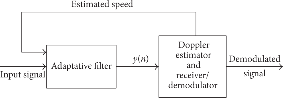
Basic block diagram of the Doppler-shift and multipath effect correction algorithm.

Synthetic and real trace example obtained using the proposed framework.
This algorithm is proposed as an improvement to the already developed ultralow power acoustic modem [1]. Doppler-shift and multipath effects had not been initially handled by this modem but were essential to the goal scenario [2].
The starting point is a coherent-FSK modem that was modelled using SPICE models used for the original modem design [1] and original C code run in the main microcontroller which can be reused for both modulation and demodulation in our framework.
As presented in [1] the key component of the design is the FSK decoder: the Phase Locked Loop or PLL. This block is a control loop and its Laplace transform response is (1)

In (1)
5.2. Initial Implementation
The proposed algorithm block diagram is shown in Figure 6. This diagram is a direct representation of the first prototype used in Octave to run the initial simulations of the algorithm.
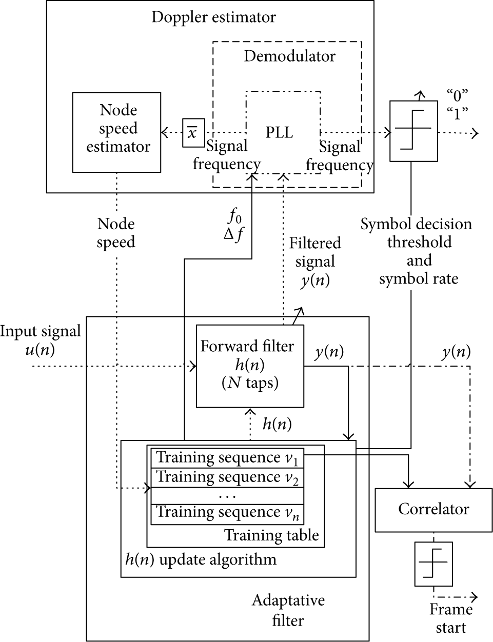
Detailed block diagram of the correction algorithm.
The different blocks are explained in detail in [2]; however, the main details of the solution are as follows: Doppler estimator LMS algorithm correlator


5.3. Initial Simulations
The next stage in the proposed workflow is to provide the simulation environment for the proposal. As stated earlier, modem hardware blocks have been modelled using SPICE, the FSK modem is implemented in C, and an initial approximation of the algorithm is described using a block diagram.
Underwater acoustic channel accurate modelling has proved to be essential in performing useful simulations [21]. The framework is able to embed any of them, including channel dynamics [34].
Models such as the empirical Thorp's formula [22] are quite straightforward to implement. Nevertheless, recent studies indicate a preference for ray tracing models [21]. These models are based on the solution of the ray equations which use the Sound Speed Profile, bathymetry, and floor sediments (which can be obtained from the WOSS database). Of these models, the Bellhop model assumes cylindrical symmetry and the ray equations can be rewritten as (5)
In this example, the scenario is set to a depth of 3 meters and a range of 200 meters. This is the recreation of the final deployment scenario: a small craft marina located near Valencia (GPS: 39.562°N, 0.283°W). Bellhop acoustic model estimation is shown in Figure 7; rays traced to simulate the channel propagation are shown in Figure 7(a), and acoustic field attenuation is shown in Figure 7(b).

Bellhop channel model estimation.
In addition, the time domain signal Doppler-shift due to the relative movement of the receiver and the transmitter is described by (6) [35]. This phenomenon is also simulated by the channel model
5.4. Proposal Evaluation and Algorithm Tune Loop
The main advantage of IUmote framework is its capacity to rapidly evaluate several proposed algorithms or hardware systems. Unsuitable approximations can be discarded before they are implemented in the final system. In addition, some valuable feedback can be reused from previously discarded designs in order to obtain new successful solutions.
The design process starting point is a FSK modem, with no extra correction algorithm. Thus, the very first proposal is the first modem model. The results obtained from the evaluation of this solution are used as feedback for the next proposal.
As shown in Figure 8 (solid line), the modem with no extra correction is not reliable even if there is no relative movement between nodes. Depending on the location, Bit Error Rate (BER) reaches 20%.

Simulation results (
The results for the simple FSK modem show a correlation between modem movement speed and the BER in all proposed locations. Doppler-shift effect is directly related to the modems relative movement [35]. Thus, it was felt that the next proposal would have to implement Doppler-shift correction. This solution improves upon the initial modem performance in most cases (Figure 8 dashed line), but there are still some locations in which performance is still unacceptable (BER ≃ 20%). Nevertheless, if the results of this simulation had shown that this solution was good enough, it would have saved a great deal of designing effort (no more design iterations) and resources (since FSK decoder could be reused as Doppler-shift estimator).
To design an optimal multipath algorithm independently of the Doppler correction algorithm, another proposal is evaluated considering only this issue. The feedback obtained from the evaluation of this solution (Figure 8 dot-dashed line) is very useful in later proposals. Thanks to this proposed framework, the evaluation is performed quickly, with the added benefit of having both the design and the results available for later reuse.
As expected, neither Doppler-shift nor multipath correction algorithms alone are reliable for this scenario. So the final iteration of the loop is the combined multipath and Doppler-shift correction algorithm shown in Figure 6. Results are not shown in Figure 8 as BER is always negligible. All the design work carried out on previous proposals has been reused to obtain this successful solution.
5.5. Native Implementation of the Algorithm
As stated earlier, a given algorithm can be implemented in a numerical analysis software or, directly, in C/C++ language. In this particular example, we started with a numerical implementation and, when the algorithm was adequate, it was translated to C. Thanks to the proposed modelling infrastructure, the translation to C is a straightforward process.
As a sample, we have included the list in the appendix which is part of the transmission functions included in the final implementation of the algorithm. The
The code can run as part of the numerical analysis software or as a stand-alone code in a deployed modem. As mentioned in Section 3, this is achieved using CheadDAQ libraries and conditional code compiling. In simplified terms, the functions in CheapDAQ with names starting with
The generated wave that must drive the piezotransducer is not played immediately; instead, it is stored in the microcontroller side and, when completely generated, it is played. This circumvents both the speed restrictions of the master-slave link and a possible processing limitation of the modem.
5.6. Real Testbed Deployment
Field tests are usually the most time-consuming tasks of the underwater design process. These tests should therefore be optimized in order to reduce them to a minimum but carefully planned in order to obtain actual relevant information. Since final implementation also takes a good deal of time, the proposed IUmote physical modem is used to facilitate this process.
As mentioned in the section explaining workflow (Section 3.2), only the most promising solutions are candidates for evaluation on the real testbed. Thanks to previous simulations the number of experiments needed to find a suitable solution and their evaluation in real scenarios is significantly reduced.
Moreover, the proposed solution can be executed offline in the laboratory and the generated synthetic traces can be loaded in the modem to generate actual signals. The received signal is sampled and stored in real traces that can also be processed offline using the different proposed algorithms. Moreover, the recorded traces can be reused to tune the receiving side algorithms since real traces can now be used as inputs.
Finally, this process allows for an intuitive preparation of a batch of experiments before field testing, reducing experimentation time. The proposed framework can be programmed offline to transmit different generated synthetic traces on the different modems deployed as well as the receiving modems which record the signal on the receiving side. Once programmed and deployed, all the experiments are automatically run, and all the results are stored in different trace files for later processing.
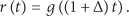
Testbed deployment is summarized in Figure 9. A laptop is used to upload and download modem trace files. Using this setup, experiments can be run in a short time. Coordination between modems is carried out using WI-FI.
Proposed testbed deployment diagram.
As mentioned earlier, the proposed scenario for both simulation and real testbed deployment is a small craft marina. The example of a node of the testbed is shown in Figure 10. An example of the collected signal is shown in Figure 5(b).

Real testbed deployment prototype.
5.7. Results Analysis and Validation
Recorded real traces are now processed using the proposed receive algorithms offline. The results are analysed and can be compared with the simulation.
As expected, recreating simulation conditions is difficult and field tests are used to validate certain cases. To recreate the conditions described in [2], nodes are placed at a distance of 6 meters (high SNR and worst case in multipath scenario) and the receiving node is moved using three different speeds: −1, 0, and 1 m/s to obtain a Doppler frequency shift. Only the initial proposal (no correction) and the final proposed solution (multipath and Doppler-shift correction) are considered. Results are summarized in Table 1.
Experimental mean error rate probability with different algorithms and receiver speed.

The results match the trends shown in simulation (Figure 8): the greater the speed, the higher the BER under no correction conditions. Moreover, errors are always corrected when using the full proposed algorithm.
Finally, the real testbed can be used to recreate modem conditions that cannot be performed under simulation. For example, algorithm convergence depending on the modem state is a critical issue when asessing its reliability under a fixed algorithm training sequence. Using this platform, convergence of the two proposed blocks has been evaluated and the results are shown in Figure 11. Using a long training sequence, convergence of the algorithms is estimated in 30 ms (Figure 11(a)). Later tests using a 31 bit training sequence (@ 1 kbps) have confirmed this assumption.

Doppler-shift and multipath algorithms convergence.
6. Conclusions
A new mathematical modelling methodology for designing underwater wireless sensor networks has been presented. This methodology facilitates the development of generic, scalable, and flexible solutions. The approach is based on specially designed modem architecture, a set of simulation tools, a combination of real and synthetic communication traces, and a workflow.
As a result, the time and effort expended between algorithm proposal and its effective deployment are significally reduced. Thanks to this proposed modelling process, hardware components or algorithms are easily modified and reevaluated.
This proposed workflow has been successfully applied to the design and evaluation of a new state-of-the-art Doppler and multipath correction algorithm, proving its advantages.
Currently we are enhancing testbed deployment. Embedded computers are used to dynamically reconfigure modems and networks remotely.
Footnotes
Appendix
See Algorithm 1.
}
{
}
Conflict of Interests
The authors declare that there is no conflict of interests regarding the publication of this paper.
Acknowledgments
The authors gratefully acknowledge financial support from the CICYT ANDREA: Automated Inspection and Remote Performance of Marine Fish Farms (CTM2011-29691-C02-01), RIDeWAM: Research on Improvement of the Dependability of WSN based Applications by developing a hybrid monitoring platform (TIN2011-28435-C03-01), Valencian Regional Government under Research Project GV/2014/012, and Universitat Politecnica de Valencia under Research Project UPV PAID-02-12. The translation of this paper was funded by the Universitat Politècnica de València, Spain.