
Abstract
Wormhole attack is one of the severe threats to wireless sensor and ad hoc networks. Most of the existing countermeasures either require specialized hardware or demand high network overheads in order to capture the specific symptoms induced by the wormholes, which in result limits their applicability. In this paper, we exploit an inevitable symptom of wormholes and present Pworm, a passive wormhole detection and localization system based upon the key observation that a large amount of network traffic will be attracted by the wormholes. The proposed scheme is passive, real-time, and efficient against both active and passive wormholes. Our approach silently observes the variations in network topology to infer the wormhole existence and solely relies on network routing information. It does not necessitate specialized hardware or poses rigorous assumptions on network features. We evaluate our scheme through extensive simulations of 100 to 800 nodes for various network scales and show that Pworm is well suited for false alarms, scalability, and time delay in terms of activation as well as detection latencies.
1. Introduction
Wormhole attack [1–6] is one of the serious security issues in wireless sensor networks in which attackers tunnel the packets between distant locations in the network through a high-speed link as shown in Figure 1. The wormhole tunnel gives an illusion to two distant nodes that they are close to each other. Thus, wormhole nodes can attract a large amount of network traffic and, as a result, collect and manipulate the network traffic to launch a variety of attacks such as dropping, corrupting, and modifying the packets. Using the wormhole links, the attacker is able to gather enough packets to exploit the wormhole attack as a stepping stone for other more sophisticated attacks, such as man-in-the-middle attack, cipher breaking, and protocol reverse engineering. This paper focuses on detection of passive and active wormholes. For passive wormhole, the adversary passively attracts and forwards the network traffic via high-speed link, while the active wormhole can actively sense the change in network status and adapt its attack policy accordingly. For example, if a network controller intends to gather the network topology for wormhole detection by flooding the whole network with a control packet, the wormhole attacker can perceive the injection of control packet and can cleverly pause its attack. In addition, both passive and active adversaries can capture and impersonate a valid node with its identity. We also observe that the establishment of wormhole attacks is independent of the general security mechanisms employed in the network.

Wormhole attack.
A variety of countermeasures have been proposed to detect wormholes in wireless sensor networks. In general, the existing methods either rely on specialized hardware devices or make strong assumptions on the networks. For example, some approaches are based upon geographical locations of the nodes that required GPS [1, 7, 8] or directional antennas [2, 9, 10] which introduce significant amount of hardware cost, energy, and computational overhead. Some other approaches pose strong assumptions on the network, such as global tight clock synchronization [7, 11], special locater nodes [6, 12], special detection event [13, 14], or use network diagnosis [15, 16]. Such requirements largely restrict their applicability in networks and few methods have been proposed to identify the locations of the two end points of the wormhole. We emphasize that such approaches cannot resist an active wormhole adversary; that is, the attacker can cleverly avoid its detection by temporarily pausing its attacking behavior or purposefully stopping the high-speed wormhole link.
In this paper, we propose a passive and real-time wormhole detection scheme, named Pworm, which can detect and localize both active and passive wormhole attackers in wireless ad hoc and sensor networks. The underlying methodology is based upon the observation that normal nodes in a network try to find the shortest path to the sink node, which leverages the wormhole attackers to attract a large amount of network traffic while introducing a high-speed link between them. As a result, a large portion of path lengths in the infected network would be reduced significantly as compared to path lengths in a clean network. Another attribute of wormhole high-speed link is that the wormhole attackers appear more frequently in network paths compared with normal nodes because a large number of paths pass across them. By exploiting these observations, Pworm counts the frequency of the presence of all nodes and calculates the path length variations to determine and localize wormhole attackers. More specifically, Pworm comprises two major parts: the topology collection and the wormhole detection. During the topology collection phase, Pworm proposes a real-time secure packet marking algorithm to gather the routing information in the given network against packet modification or dropping by wormholes. In the wormhole detection phase, the network controller, say sink, analyzes the changes in collected path information to determine the appearance of wormholes and locates the wormholes accordingly.
Our approach has three key advantages. First, Pworm is a passive wormhole detection scheme. By using Pworm, the active wormhole attackers cannot circumvent the detection because Pworm employs a passive path information collection scheme; that is, it makes use of regular network traffic and does not introduce any special packet to inform nodes about the detection event. Also, the path information is gathered passively at the sink throughout the network routine operation. This way, the active attackers cannot sense the detection event. Second, Pworm is highly friendly on network overhead and computation. In terms of network communication overhead, Pworm only and slightly modifies the packet forwarding pattern of the nodes (i.e., packet marking). For computation, the wormhole detection and localization only happen on the sink instead of resource constraint nodes. In addition, there is no additional hardware required in Pworm. Third, Pworm is a real-time approach which can quickly find wormhole attackers.
The major limitation of Pworm is that it is a probabilistic method. The wormholes may not be detected if they attract little traffic. However, we observe that if less traffic is absorbed by wormhole attackers, less damage will happen to the network. The efficiency of our proposed model becomes better once wormholes sink more and more packets in the network.
We make the following two contributions in this paper:
We propose a real-time wormhole detection and localization approach with minimal network and computation overhead for wireless ad hoc networks. We present Pworm to detect active wormhole attackers which operates in a passive mode to avoid the process detection by the adversary.
The rest of this paper is organized as follows. Related work is discussed in Section 2. We present the system model and design goals in Section 3. Our approach is described in Section 4. We conduct a security analysis in Section 5. We extensively evaluate our system in Section 6 and elaborate its performance in terms of activation and detection latency, time delay, network topology, and scalability for both active and passive wormhole attackers. The paper concludes in Section 7.
2. Related Work
Existing countermeasures mainly rely on the observations based on the symptoms induced by wormholes.
2.1. Approaches Based on Special Hardware
Hu et al. [7] proposed an approach that uses geographical and temporal packet leashes. This approach is limited by the requirement of GPS technology or time synchronization. Čapkun et al. [1] proposed a protocol, called SECTOR, which relies on a special hardware to accurately measure the distance amongst the nodes. In [17–19], the authors have used the beacon nodes which are location-fixed nodes with their positions known in advance, and sensors are position-unknown nodes that need to locate themselves with the assistance of beacons. Here, the nodes having unusual transmission range are assumed to be the wormhole nodes.
2.2. Approaches Based on Strong Assumptions
2.2.1. Time Mismatch
Some approaches are based upon time mismatch between packet transmission and reception. In [20–24], it is assumed that the controller and nodes in a given network can perform accurate time synchronization to calculate the Round Trip Times (RTTs) of the packets to estimate the distance between the source and destination for every packet. By comparing the estimated distance with the valid communication range, wormholes can be exploited. However, these approaches are constrained by accurate time synchronization. Chiu and Lui [25] compared the delay per hop of a legitimate path with the delay per hop of a path that is under wormhole attack. The key assumption is that the delay per hop of the legitimate path is smaller than the one under attack. In their method, they flood the entire network with packets and then find their different paths to destination to calculate and compare the delay per hop in each path.
2.2.2. Neighborhood Mismatch
Some approaches observe the symptom of neighborhood mismatch which is physically infeasible. Hu and Evans [2] used the directivity of directional antennas on sensor nodes to locate the infeasible communication links. Khalil et al. [26, 27] proposed LiteWorp and MobiWorp, in which each node collects information regarding its 2-hop neighbors and selects guard nodes to detect wormhole channels by overhearing any infeasible transmission among nonneighboring nodes during the deployment phase. Choi et al. [28] measured the RTTs between neighbors, identifying that two neighbors which are not within each other's communication range are supposed to be suffering from wormhole attack. Other approaches make use of local and neighborhood information to detect wormholes [14, 29, 30].
2.2.3. Graph Mismatch
Some approaches [12, 31–33] are based upon graph mismatch under network graph models. These schemes, however, make strong assumptions on the network model. The major constraint is the considerable amount of packet transmission and forwarding performed by nodes to investigate the symptoms of graph mismatch, which is not practical for resource constraint nodes. Maheshwari et al. [34] proposed a scheme for wireless multihop networks which uses connectivity information to look for forbidden substructures in the connectivity graph and detects any change that can be the source of wormhole attacks. Dong et al. [13] proposed a topological method to discover wormholes. They explored the fact that a legitimate multihop wireless network deployed on a geometric terrain can be classified as a 2-manifold surface of genus 0, while the wormholes in the network inevitably introduce singularities or higher genus into the network topology.
2.2.4. Statistical Analysis
References [35–37] proposed a method based on path or link statistical information. However, this method is limited for multipath on-demand routing protocols. Buttyán et al. [38] based their approach on the statistic information about the number of neighboring nodes and the distances between each pair of nodes. Thus every node should actively report this piece of information which causes heavy communication overhead.
We emphasize here that all existing works discussed above are only focused on detection of passive wormhole attacks. These methods underline the assumption that wormhole nodes cannot sense any detection event. In contrast, an active wormhole attacker can actively sense the symptoms of detection event and can temporarily pause its attack to avoid the detection [39–42]. To address this situation, we propose a real-time wormhole detection scheme which is well suited for the detection of both passive and active wormhole attackers.
3. System Model and Design Goals
In this section, we firstly describe models of network and adversary capabilities and then present our design goals.
3.1. System Model
3.1.1. Network Model
We view the sensor network as a base for data acquisition, in which source nodes periodically sample data and deliver it to the sink through multihop communication. Our approach deals with networks of various communication topologies such as Spanning Tree.
The life time of a sensor network comprises two phases: bootstrapping and running. In bootstrapping phase, sensor nodes and the sink are deployed by a legitimate user and we presume that there are no wormhole nodes in the network. During the network running phase, wormhole nodes will be placed within the network area.
3.1.2. Adversary Capabilities
In Pworm, wormhole nodes can be divided into two categories: passive and active wormholes. Passive wormholes attract traffic by means of a wormhole link and they cannot detect any wormhole detection event. Instead, active wormholes not only attract the network traffic, but also adaptively determine their attacking policy according to the situation in the network. For example, in [7, 13] to detect wormholes, the sink node floods a command to all network nodes to request the adjacency list of each. This command flooding, however, is an obvious symbol of an wormhole detection event, for which the active wormhole nodes can adaptively adjust their policy accordingly (e.g., temporarily suspend the wormhole link) to avoid such detection.
3.2. Design Goals
In current wireless sensor networks, most sensor nodes are resource constraint on computation and communication. Therefore, an effective wormhole detection and localization scheme should be light-weighted in harmony with communication and computation cost. We observe that any such scheme should meet the following requirements:
Real-time detection: the scheme should detect and localize wormholes during the network running phase with low detection latency. Resilience to active wormholes: it should not depend on particular events or behavior during detection process. Instead, it should be effective at any time of network running so that the active wormholes should not be able to adjust their policy to avoid detection. Resource and computation: it should not introduce tight assumptions in terms of hardware resources, network overhead, topology, computation, or power. The design will be best suited if it is fully operational within existing network resources or brings minimal overheads to it.
4. Pworm Design
We first highlight the chief characteristics of wormholes and the impact of wormhole attack, which is the underlying observation in our scheme. Later we present an overview of our scheme followed by detailed explanation.
4.1. Preliminary Observations
As illustrated in Figure 1, there exists a high-speed wormhole link between two wormholes which is very likely to be involved in routing of other network nodes because the shortcut can effectively reduce path lengths of the normal nodes. As a result, wormhole nodes can attract large amount of traffic in the network and perform attacks. In the following sections, we illustrate two salient features of wormholes which work as basis for our proposed methodology.
4.1.1. Traffic Attraction
Nodes in a wireless sensor network usually choose the shortest path to the sink due to energy and delay concerns. Thus, the shortcut wormhole link which effectively shortens the path lengths will attract lots of packets moving towards the sink. As a result, wormhole nodes can attract large amount of network traffic. To illustrate this, we compare the network traffic passing through a node which acts like a normal node and then as a wormhole node for comparison purposes. As shown in Figure 2(a), a wormhole node can absorb 28% more traffic than a normal node operating at the same physical position in the network that comprises 300 nodes. During our evaluation, we deployed two wormholes in the network which can be passive and active attackers depending upon evaluation scenario. Since large attraction of network traffic means the high capability of wormholes to manipulate the network, the wormholes were positioned at specific places in order to enable them attract as much traffic as possible.

Symptoms of wormhole attack.
4.1.2. Path Length Decrement
Typically, wormhole nodes are wide apart from each other and they introduce a wormhole link to attract more traffic. A packet forwarded through wormhole nodes thereby travels a significantly shorter path than once routed through normal nodes. In essence, wormholes can remarkably decrease the packet path length (number of hops of a path) in the network. Figure 2(b) illustrates the decrement in path length caused by wormholes in different scales of the networks. Overall, we observe that wormhole nodes slightly decrease the average path length of the whole network (not more than 3 hops). Moreover, they significantly reduce the path length of the nodes which select wormhole link as part of their paths. Therefore, we can exploit the feature of path length decrement to detect the wormhole attacks.
4.2. Pworm Overview
We present a real-time wormhole detection and localization approach, Pworm, for running a data acquisition sensor network. Pworm implants minor modifications on each sensor node to mark the routine application packets in a network. As a result, the sink can reassemble a broader status of the network conditions from these small clues. Nevertheless, information from packet marking is quite limited and not sufficiently accurate. Based upon this packet marking, Pworm performs the evaluation of negative symptoms to detect wormholes. These symptoms can be the abnormal network situations such as path length decrement or traffic attraction. The whole architecture is depicted in Figure 3.

Pworm architecture.
4.3. Packet Marking on Sensor Nodes
Unlike an enterprise network, a sensor network has a self-organized and time varying network structure in which no prior knowledge is readily available for the detection method. Also, as the topology of sensor network can be highly dynamic, we need to continuously acquire the network status to maintain the routing information. More importantly, we need a technique to guarantee the integrity of markings to protect them from viable wormhole modifications. To address the stipulated requirements, we design a packet marking algorithm in Pworm which dynamically captures the network topology and ascertains the inner dependencies amongst the sensor nodes. As a result, the marked packets are delivered to detection module at sink, which reconstructs the network topology and extracts information regarding packet paths in the network.
4.3.1. Design Methodology
The main operation of packet marking algorithm is to let sensor nodes stamp their IDs on passing packets. The major challenges we face here are the following: How to design a functional yet efficient scheme that incurs less memory cost and communication overhead. The scheme should address the problem of duplicate markings and mark integrity as per security measures against wormhole vulnerabilities. Most importantly, the packets should be marked in line with size limitation of packet lengths.
To meet aforesaid requirements, we formulate a packet marking scheme based upon set of rules. Our system outputs an attack detection alert at the level of intermediate network nodes. As this alert can either be the result of a wormhole link or be from a change in network topology, therefore for a fine-grained detection, we perform further analysis at sink where overall network topology is reconstructed and analyzed. We first illustrate each aspect of the scheme and then comment on overall operation of the system.
4.3.2. Packet and Cache Structure
Our scheme requires negligible addition to each network packet (Figure 4(a)) and slight memory retention at each node, which we call cache (Figure 4(b)). Illustrated as “original part” in Figure 4(a), we assume that each data packet consists of the following: a source node ID that designates the source of the packet; a sequence number identifying the packet; and a Hopcount recording the number of hops it travels. If an application misses any of these attributes, the marking scheme adds them to the packets. Next, the mark (“mark field” in Figure 4(a)) consists of three parts: the Mark ID which records the ID of a sensor that marks the packet; the preceding ID that states the node ID prior to the node which marks the packet; and a message authentication code (MAC) which guarantees the integrity of all marked fields by using the secret key k shared between this node and the sink against viable wormhole modification (any normal MAC from a cryptographic hash function can be used).

The content of mark and cache.
Each intermediate node maintains a cache as illustrated in Figure 4(b). Each cache entry consists of a source node ID, a list of all past sequence numbers of the packets received from the source node, and the number of hops from the source. Once the source node generates a new data packet, it initializes the Hopcount field with zero, the preceding node ID with its own ID and MAC for the preceding node ID and sequence number. The node cache serves two main purposes. First, it prevents the node to mark a packet more than once. Second, it works like a local check-sum as it correlates sequences number and Hopcount of each packet to its stored values and generates an “Attack Alert” message in case of any manipulation. Since these parameters can be changed either from wormhole attack or because of dynamic changes in network topology, we perceive “Attack Alert” as an initial guess for further calculations at sink.
4.3.3. Neighborhood Proximity Rule
Our design methodology relies on the scheme that packets are marked only once following the neighborhood proximity rule, which serves the issue of inadequate packet length. This is performed by Mark ID in each packet structure. Consider an honest network where the source generates its first packet (
Once
4.3.4. MAC Configuration and Calculation
Each node calculates a message authentication code, MAC, irrespective of whether it marks the packet or forwards it to next node. As MAC calculation guarantees the integrity of all marked fields against viable wormhole modification, we elaborate different configurations of MACs depending upon network conditions. Once a node marks the packet, it calculates the MAC as MAC(k, Mark ID, preceding node ID, Hopcount, original MAC), where k is the key shared between this node and sink. Once a node receives a marked packet, it checks the sequence number and the Hopcount. If the sequence number is consistent and Hopcount is identical, it calculates MAC as MAC(k, sequence number, preceding node ID, original MAC). If the sequence number is consistent but Hopcount is not identical, then an Alert Message is generated and MAC is calculated as MAC(k, mark node ID, sequence number, Hopcount, original MAC). Once a node receives a marked packet, but the sequence number is not consistent, node calculates the MAC as MAC(Mark ID, original MAC, Hopcount).
4.3.5. Illustrated Operation
Having defined various parameters and functions of packet marking scheme, we now illustrate the overall operation from network point of view. As shown in Algorithm 1, upon receiving a packet P, an intermediate node first checks whether the packet has been marked. If yes (Mark ID is not empty), it forwards the packet without any operation. If the Mark ID is empty, the node checks its own cache. If there is no entry for the source node ID of this packet, it marks the packet by filling the Mark ID field with its own ID and calculating the MAC for the Mark ID, the preceding ID, and the Hopcount. Afterwards, it also creates a new entry for this source node in its cache and records the Source ID, sequence number, and Hopcount for the packet. If Mark ID is empty and there exists an entry in the cache for the source node and the sequence number which is consistent, the intermediate node firstly compares the Hopcount in the packet P with the one in the cache. If identical, the node updates cache entry with the new sequence number and increases the Hopcount in the packet P by one. Meanwhile, it records the preceding node ID in P with its own ID and replaces the MAC field with MAC(k, sequence number, preceding node ID). Otherwise, the node replaces the Hopcount and preceding node ID in P with the Hopcount in the cache and its own ID, respectively. Then it marks the packet with “Attack Alert” message and the MAC with MAC(k, Mark ID, sequence number, Hopcount). If Mark ID is empty and there exists an entry in the cache but the sequence number is not consistent, the node marks the packet with its ID in Mark ID and replaces the original MAC with MAC(k, Mark ID, original MAC, Hopcount). Finally, it updates the entry in the cache with new sequence number and Hopcount and then forwards the packet. It should be noted that the original MAC is computed by the preceding node which is prior to the intermediate node. If the network remains static, the packet marking process automatically converges and stops after the routing tree for entire network is constructed. At sink side, the mark parsing module retrieves paths from each source node through analyzing chronologically marked packets and reconstructs the network topology along with the regular data delivery of the system. When network conditions vary such as wormhole link or dynamic path changing occurs, the packet marking process restarts somewhere close to the suspected wormhole event.
(1) (2) Forward packet P; (3) (4) Check cache; (5) (6) Mark P with its own ID and fill in the MAC field with MAC(Mark ID, MAC(preceding node ID), Hopcount); Create entry with Source ID, Sequence number and Hopcount in P; (7) (8) (9) Update cache entry with new sequence number; increase Hopcount in P by 1 and fill in the preceding node ID with its own ID and fill in the MAC field with MAC(ID, Sequence number); (10) (11) Fill P.Hopcout field with cache.Hopcount; mark P with “Attack Alert” message and fill in the preceding node ID with its own ID and fill in the MAC field with MAC(ID, Sequence number, Hopcout); (12) (13) Mark P with its own ID and fill in the MAC field with MAC(Mark ID, MAC(preceding node ID), Hopcount); update cahce entry with new Sequence number and Hopcount;
4.4. Mark Parsing
As marked packets reach sink, it reconstructs the topological diagram based on the marking information. Like nodes, sink also maintains a cache to store the node ID, Hopcount, and sequence number of the packets. Here, we label node IDs as a path which records the node IDs from source to the sink node. The sequence number of the latest packet from the corresponding source is also stored.
As shown in Algorithm 2, once the sink receives a packet P, the mark parsing module extracts the marks and operates as follows: If the sink receives a packet for the first time from a source, it will create a new path entry for the source node and will register the Source ID and sequence number in the cache. If the received packet is not marked and hop number is same, which means that the packet has been transmitted along the same path as before, the parsing module only updates the sequence number of that path. Otherwise, if the packet has been marked, the parsing module will firstly check whether P.MAC is correct or not. More in detail, the parsing module will check two MACs, the first is the MAC(preceding node ID), and the second is MAC(k, Mark ID, MAC(preceding node ID), Hopcount) signed by the node which marks the packet. If either of the two MACs is wrong then it indicates that MAC has been maliciously modified or forged, and the parsing module will generate an attacking report for P.Source ID. In addition, the sink checks whether the mark is “Attack Alert” or not. If yes, it generates an attacking report and locates the attacker to be P.Hopcout-1 of the associated path. If the mark is not “Attack Alert,” the parsing module works as follows: Let d be the difference between the received packet's sequence number and the relevant sequence number in the associated path cache. If network works normally (no wormhole attack or topology change), there will be no packet loss and d should be equal to 1. For such case, since the packet has been signed by the preceding marked node, the only viable reason for packet to be marked is that the route has been changed. Then the parsing module checks whether the P.preceding node ID is identical to path[Hopcount-1] or not. If yes, it generates a route switch report, replaces the path[Hopcount] with P.Mark ID, and clears all nodes ID of the path after path[Hopcount]. Otherwise, it generates an attacking report and locates the attacker to the path[Hopcount-1] on the associated path. If d is not 1, there must be packet loss in packet forwarding process. The parsing module generates a packet loss report and then checks whether path[Hopcount] equals P.Mark ID. If yes, then there is no further operation. Otherwise, the parsing module will first clear all node IDs of the path after path[Hopcount-d] and then replaces path[Hopcount] with P.Mark ID. It finally generates a route switch report as this case only happens when the route varies on the associated path.
(1) (2) Create a new path for P.Source ID; (3) (4) (5) Update the Sequence number of the corresponding source; (6) (7) (8) Generate attacking report on path P.Source ID; (9) (10) (11) Generate attacking report at location P.Hopcout-1 of that path; (12) (13) (14) (15) (16) Generate attacking report at location path[Hopcount-1] of that path; (17) (18) Set path[Hopcount] = P.Mark ID; clear all nodes' ID of the path after path[Hopcount] and generate route switch report; (19) (20) Generate packet loss report. (21) (22) Clear all nodes' ID of the path after path[Hopcount-d]; set path[Hopcount] = P.Mark ID; generate route switch report;
4.5. Wormhole Detection and Localization
After mark parsing, the sink can reconstruct all paths in the network. By monitoring path variations, the sink ascertains the symptoms caused by the wormholes. The sink thereby calculates the following two factors to find wormholes.
Proportion of Changed Paths. As wormhole nodes attract a considerable amount of network traffic, a large number of paths are also changed accordingly. Unfortunately, as the topology dynamics of network can also result in path variations, therefore, Pworm employs a more discrete and fine-grained method to differentiate between path variations caused by the wormholes and the network topology. We differentiate both entities with the key observation that the wormholes incur a considerable number of path variations compared with the topology dynamics. For Pworm, we conduct a comprehensive simulation to illustrate the said difference. As a result, we can set up a proper threshold for the proportion of path changing to distinguish the wormholes from topology dynamics. Details of the threshold settings are presented in Section 6.3.
Length Decrement in Changed Paths. As described in Section 4.1, wormhole attack reduces the lengths of changed paths significantly. In Pworm, we also count this factor for wormhole detection.
4.5.1. Wormhole Detection
The detection algorithm is described in Algorithm 3. Pworm collects the routing information (denoted as U) after the network bootstrapping phase and the real-time routing information (
(1) Compare U with (2) (3) Average deceased length = (4) (5) Wormhole exists; save the network routing info and ready to locate the wormhole node; (6) (7) Topology dynamics and no wormhole existing; (8) (9) No wormhole existing;
4.5.2. Wormhole Localization
As compared to topology dynamics, we make a prime observation that wormhole attack is the main reason of path length decrement, and wormhole nodes should appear in most of the changing paths. Therefore, to locate wormholes, we count the appearance of nodes amongst all the changed paths and figure out two nodes which have the maximum number of occurrences. As a result, we can locate wormholes as these two nodes or nodes within one-hop neighbors of these nodes.
Remark. Wormhole detection in Pworm is based on the proportion of changed paths, but at the same time it is also likely that network dynamics will change a considerable proportion of the paths. This relates to practical scenarios in wireless sensor networks; for example, some nodes run out of energy upon inadequate power. If some nodes stop working in a path, the path will break and packets will be routed through another path to reach the destination. This means that although we set a threshold to distinguish between network dynamics and wormhole attack, still, there may be some situations where network dynamics changes the paths while there is no wormhole in the network. Such a situation can result in false positives in our detection. In Pworm, we solve this problem through leveraging the threshold and resultantly we can restrict false positives nearly to zero. In addition, we find out that if there is no big difference between effects incurred from wormhole attack and network dynamics (which makes relative high false positive), wormholes cannot attract sufficient traffic to perform attacks.
5. Security Analysis
Wormhole attacks can be passive or active. A passive attacker can only receive packets and forward them via high-speed link between wormholes, while an active attacker can adaptively change its attacking policy to avoid detection. For example, an active attacker can temporarily suspend the high-speed link once it observes the symbols of detection event, such as a control command from the sink to collect the adjacency matrix of each node in the network [7] or a probing packet to find the loop in the network topology caused by the wormholes [13].
In Pworm, there is no symbol of detection event as sink passively collects the network path information and performs detection at all times. This results in a passive and real-time detection of both active and passive wormholes even during the network running phase. However, passive and active wormholes can perform certain attacks on Pworm by intentionally interrupting the path collection at sink (through dropping packets), fake packet marking, random packet forwarding, and not participating in marking event. In this section, we analyze the security of Pworm under these attacks.
5.1. Passive Wormhole
For Pworm, we divide the passive wormholes attacks into two categories: the wormholes which mark their IDs and which do not mark their IDs. For the first case where passive wormholes mark the packets, the sink can locate the wormholes accurately as their IDs are visible to the sink. In second case once wormholes do not mark the packets intentionally but try to perform an attack, the sink cannot find their IDs in paths but still can locate wormhole's neighboring nodes as these neighbor nodes appear in gathered paths.
5.2. Active Wormhole
Active wormholes can try to avoid detection by misleading the sink to gather wrong path information through modifying the marks in the packets. As described in Section 4.3, the secure packet marking algorithm protects the marking fields in a packet with message authentication code (MAC) except Hopcount field. Therefore, an active attacker can only modify the Hopcount field in a packet. Otherwise, any other modification will be noticed by the sink during the mark parsing phase. For an attacker to forge a wrong Hopcount in a mark, there are two choices: forward the packet through the path on which other packets are travelling or randomly select another neighboring node to forward the marked packet.
In case of first choice once a wormhole transfers its packet by selecting path of another packet, the attack is detected as the neighboring node, in proximity of wormhole, receives the marked packet and looks up to its cache entry which has record of the packet information. By comparing two Hopcounts in the cache, the neighbor node can find out the inconsistency and will report the probable attack with Attack Alert message.
In second choice, the active attacker randomly selects another neighbor for packet forwarding. Once the packet reaches the attackers neighboring node, it will create a new entry for this packet in its cache as it is not aware of the mark modification. In this case, the sink can discover the modification during the mark parsing procedure. Specifically, the sink will retrieve the order of node from every received path by checking the consistency between path[Hopcount-1] and
Lastly, in case of both passive and active wormhole attacks, if the attacker randomly drops packets to escape from detection, the parsing module can observe the phenomenon of frequent packet losing. Then the sink would locate the sources where packets are lost frequently and will report an alert.
6. Evaluation
6.1. Experimental Setup
During evaluation, we randomly deploy 100 to 800 sensor nodes in a 25 × 25 grid configuration to simulate an experimental network containing the wormholes. Each node is set to transmit one packet per second. As described earlier, passive attackers can only receive and forward packets through high-speed link, while in contrast the active attackers can randomly select a neighboring node for packet forwarding at the entrance or exit of the high-speed link. Since Pworm is a passive and real-time approach, so both active and passive wormholes cannot discover the detection event and will keep performing their attack during the lifetime of the network.
6.2. Metrics
As Pworm is a probabilistic algorithm, it will determine the wormhole existence with some probability of error. We, therefore, employ False Positive Rate (FPR) and False Negative Rate (FRR) to represent probabilities of false decisions, given by

6.3. Experimental Results
6.3.1. False Negative
We investigate the average false negatives for a network configuration that comprises 800 nodes. The results are plotted in Figure 5(a) for active wormholes and in Figure 5(b) for passive wormholes. We observe that false negative is stable under both cases if the threshold (the proportion of changed paths observed by the sink, as described in Section 4.3) is less than 5%. However, the false negative grows sharply as we increase the threshold above 5%. Hence, we can choose a proper threshold within 15% to achieve high accuracy as shown in Figure 5. For thresholds >5%, the false positive remains zero but the false negative increases rapidly. While for threshold <1%, slight network dynamics can falsely trigger the detection process and incur false alarms which means high False Positive Rate and low accuracy. As we mainly focus on the detection rate of true wormholes (i.e., achieving low False Negative Rate), we only plot the False Negative Rate along with threshold in Figure 5. We also observe that as the number of nodes increases, the false negative ratio decreases. This is obvious for 100 to 400 nodes in both Figures 5(a) and 5(b). This reduction is more illustrative once threshold is beyond 5%. We see a rapid drop once node population is increased from 100 to 200. The same noticeable decrease is visible till node size of 400. For higher sizes like 500–800 nodes in both active and passive wormholes, we observe that false negative is nearly consistent regardless of the number of nodes. This is because of the reason that as the nodes increase, the network traffic increases and the chances for a wormhole to attract little traffic or change inadequate path lengths also decreases; that is,

False Negative Rate versus threshold for 100–800 nodes shown for active and passive adversaries.
6.3.2. Time Delay
The time delay in Pworm comprises two types: activation and detection latency. The activation latency is the time required by the sink to collect enough information regarding path changes since the wormhole deployment. The detection latency is the time utilized by sink to effectively locate wormholes after being activated. The results of both time delays are shown in Figure 6 for active and passive wormholes. The results are plotted against various threshold values for a population of 100–800 nodes. To show the impact of network population (the number of nodes), Figure 6(a) plots the results for a sparse network that consists of 100 to 400 nodes while Figure 6(b) shows the results for a dense network that comprises 500 to 800 nodes.

Activation and detection latency versus threshold for 100–800 nodes shown for active and passive adversaries.
Overall, we observe that activation latency increases along with increase in threshold level. The higher threshold means that sink needs more time to collect information of path length change. Since activation latency is mainly incurred at the initial phase of the network lifetime, therefore it can be considered as one-time overhead which would not affect the future detection events. For detection latency, we observe that it is inversely proportional to the threshold. The reason is that under small threshold values the sink is misactivated by reasons like network dynamics, which is not the case for higher threshold. Lastly in Figure 6, we see that detection latency for both active and passive adversaries is less than 8 sec which is quite acceptable for fast wormhole detection.
Because of low network traffic and path lengths for 100–200 nodes in Figure 6(a), the activation and detection latencies have nearly the identical time delays but the trend is same; that is, activation latency increases with threshold while detection latency decreases. However, for node population of 300–400, the activation latency is higher than detection latency. The same results are also observed in Figure 6(b) for 500–800 nodes whereby graphs of both latencies are nearly consistent regardless of the number of nodes. Once we compare active and passive wormholes, we observe that latency values are nearly consistent with passive wormholes always incurring slightly lower values than active wormholes. However, the trend in latency curves is same in both cases. The results in Figures 6(a) and 6(b) show that our system can be effectively deployed and sink can efficiently detect wormholes in affordable time, for both active and passive wormholes.
6.3.3. Scalability
To examine the scalability of Pworm, we set up several network configurations comprising 100 to 800 nodes. For clarity of understanding, we only show the results of false negatives for 1% and 5% threshold values in Figure 7. Figures 7(a) and 7(b) show the False Negative Rate in relation to number of nodes for both active and passive adversaries. We observe that false negative decreases with increase in number of nodes. The reason is straightforward: the wormholes cannot attract much traffic in a sparse network and thus cannot incur enough topology changes to trigger the detection event. As regards the threshold values, the False Negative Rate seems to be consistent for active wormholes once compared to passive wormholes. Moreover, the rate is higher for lower node sizes and rapidly decreases as the node numbers increase from 100 to 400. For node population of 500 and above, the false negative value is negligible and nearly constant for higher population of nodes. The False Negative Rate versus network density is shown in Figures 7(c) and 7(d). The results for active and passive adversaries are nearly the same for similar density of the network. The false negative decreases rapidly as the density of nodes increases and reaches a negligible value for a network density of 10. A sharp decline in the False Negative Rate in relation to increase in network density is quite obvious: more number of nodes will result in higher network traffic and will lead to more path changes, both of which will be easily and quickly detected by the sink.

False Negative Rate versus # nodes shown for active and passive adversaries in (a) and (b), while the False Negative Rate versus network density is shown for active and passive adversaries in (c) and (d).
Regarding time delay, the activation latency is investigated for various network topologies in Figure 8 for both active and passive wormholes. The figure provides a detailed insight into time delay in relation to number of nodes and average path length. The threshold is varied from 1 to 5%. As shown in Figures 8(a) and 8(b), the latency first increases with the increase in number of nodes, reaches its maximum value for 300–400 nodes, and then reduces with a steady decline. The reason lies in twofold: (1) For a small network, there are few paths and thereby the sink can rapidly collect the topology information of the network, which outputs a lower activation delay. From our simulation results, we observe that a smaller network comprises 300 or lesser number of nodes. (2) Considering a dense network that is containing more than 300 nodes, there are more paths compared to a sparse network but path length is reduced. Therefore, the sink can collect the network topology more effectively which decreases the activation latency. Next, Figure 8(c) shows the latency in relation to average path length. We observe that latency is lower once the network is sparse; that is, a low population of nodes will result in lower path lengths and small number of hops. Similar to Figure 8(b), we observe a change in latency once the network topology changes from sparse to dense. We observe similar results in case of passive wormholes in Figures 8(d), 8(e), and 8(f); however the values of activation latency are slightly lower once compared with the results of active wormholes.

Activation latency shown in (a), (b), and (c) for active wormholes while (d), (e), and (f) show the same results for passive adversaries. Simulation is performed for 100–800 nodes while threshold is varied from 1 to 5%. Latency increases as the number of nodes increases till 300, while it observes a decline and remains consistent for higher network configurations (400–800 nodes). The average path length is observed to be lower for sparse network while it increases as the network density and number of nodes is increased.
Figure 9 shows the results of detection latency for both active and passive wormholes. The results are similar to activation latency with slightly lower latency values. We observe that more nodes result in greater network traffic with more path lengths. Under such conditions, the wormholes will attract more traffic in a dense network which will result in more path variations. Therefore, the sink can detect the wormholes more easily in lesser time. In essence, the sink can rapidly collect network topology which results in low activation latency for a sparse network. A dense network will initiate more network traffic and will include greater path variations, which is a favourable situation for wormhole to work. As wormhole attracts more traffic and changes more path lengths, it will be easily detected by the sink which will result in lower detection latency. Similar to Figure 8, the detection latency for passive wormholes is slightly lower than active wormholes while the overall latency trend is consistent; that is, it increases for a sparse network while it decreases once the network becomes more populated.
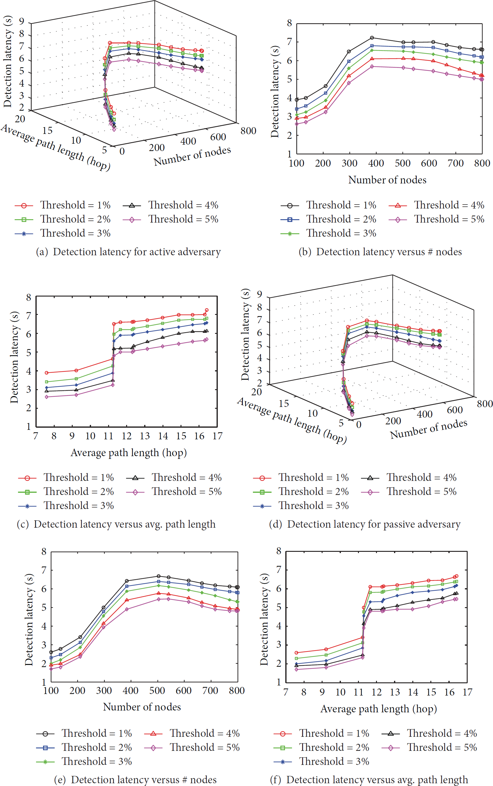
Activation latency shown for active and passive adversaries in (a). Simulation is performed for 100–800 nodes while threshold is varied from 1 to 5%. The results are consistent with the results in Figure 8; however, the overall latency values are lower once compared to activation latency.
Under all cases in Figures 8 and 9, a high threshold value will result in higher activation and detection latency. This is because the sink requires more time to observe the proportion of the changed paths. The trend of both latency values against all thresholds levels is consistent; that is, the latency first increases in a rapid manner for a lower network configuration, reaches its maximum, and then gradually decreases as network becomes more dense. The same is also observed for the case of average number of hops in Figures 8(c), 8(f), 9(c), and 9(f). The latency values are lower for smaller hops which correspond to sparse network. In contrast, the large number of nodes increases the overall latency as well as the average path length, as discussed before.
7. Conclusion
Wormhole attack is a severe threat to wireless sensor and ad hoc networks. Most existing countermeasures either pose strong assumptions on the network or require specialized hardware devices, which restricts their applicability. In this paper, we propose Pworm, a passive and real-time wormhole detection scheme by exploiting the fundamental features of wormhole attack, the path length decrement and the occurrence of wormhole nodes. By detecting the path changes in the network, our approach can detect and locate both active and passive wormholes within few seconds and relies solely on routing information of the network. Our evaluation of various network scales comprising 100 to 800 nodes shows that Pworm achieves superior performance and applicability on false negative, time delay, and scalability.
Footnotes
Conflict of Interests
The authors declare that there is no conflict of interests regarding the publication of this paper.
Authors' Contribution
Li Lu and Muhammad Jawad Hussain have contributed equally to this work and are considered as co-first authors.
Acknowledgments
This work is supported by National Natural Science Foundation of China (Grant nos. 61472068, 61173171) and the project funded by China Postdoctoral Science Foundation (Grant no. 2014M550466).