
Abstract
The structural health monitoring system has made great development nowadays, especially on bridge structures. Meanwhile, most SHM systems reported were designed, integrated, and installed into large-scale infrastructures by professionals and equipped with expensive sensors, data acquisition devices, data transfer systems, and so forth. And it is impossible to install SHM system for every civilian building. For this status, a kind of new idea for structural health monitoring using smartphone is introduced in this paper. A smartphone, with embedded responding SHM software and inner sensors or external sensors, can be used not only as a single wireless sensor node but also as a mini-SHM system. The method is described in detail, and then the swing test, cable force test in laboratory, and cable force test on an actual bridge based on the iPhone were conducted to validate the proposed method. The experimental results show that Mobile-SHM using smartphone is feasible. The realization of Mobile-SHM method using smartphones may be considered as a milestone in making SHM popular in the lives of people.
1. Introduction
Structural health monitoring (SHM), as a kind of emerging interdiscipline, is defined as follows: different kinds of sensors are put in a structure to make the structure have the ability to sense its external environmental loads and respond to these loads, in order to enhance its performance and survivability [1]. Now, SHM becomes more and more important in people's lives, and it has become a common industry standard to arrange the sensors to monitor the health of some major structures so that preventive action can be taken well in advance. However, SHM is only used on some large-scale structures and has to be accomplished with expensive monitoring system by professional staff, leading to less application in medium-mini size structure. It has become an urgent matter to make the system popular in small structures and thus play a more important role in people's daily lives when facing natural disasters (earthquake, hurricane, or floods).
The wireless sensor network and mobile communication technology [2–6] provides a good technical platform and implementation that could solve the above problems of SHM, which also makes the popularization of SHM possible. Compared with a wireless sensor, smartphone's CPU are stronger in the capacity of data collection, processing, and communication. And a smartphone as the wireless sensor with a low power CPU usually works at the free ZigBee radiofrequency band and is more reliable than a wireless sensor. More important, almost everyone has a smartphone, and it is convenient to operate and needs less professional requirements, which makes SHM popular in the lives of people. Now smartphones are broadly used in some application areas, such as remote medical treatment [7, 8], mobile library [9], remote home automation and security monitoring [10], and self-rehabilitation management [11]. Based on these facts, in this paper, a small structure monitoring method (Mobile-SHM) using the popular mobile terminal (iPhone, e.g.,) is presented. The Mobile-SHM concludes two kinds of patterns, which are the inner sensing unit of the iPhone and external sensors board based on the iPhone. In this paper, two patterns are introduced, and the swing test, cable force test in the laboratory, and the cable force test on an actual bridge are conducted to verify the implementation and feasibility of this project.
2. Project Design
2.1. Method Description
The two patterns in an iPhone are shown in Figure 1: inner sensor unit and external sensors board.
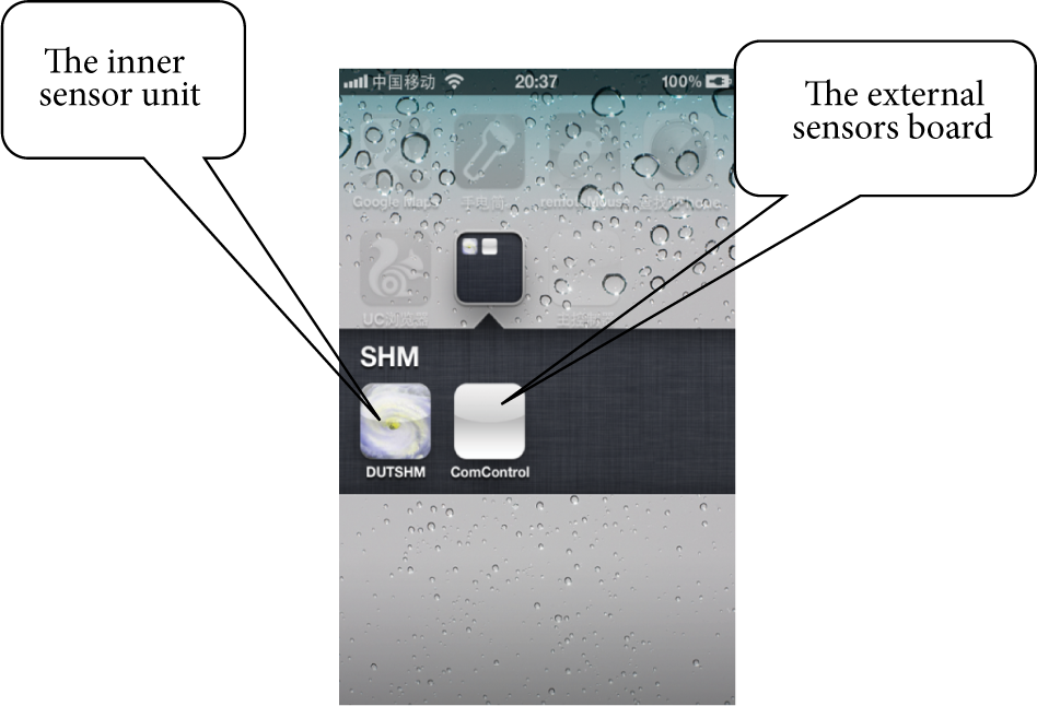
Interface in an iPhone.
The iPhone's inner sensor unit (inclination, gyro, GPS, acceleration, and brightness) is used for extracting the monitoring object's original information, for example, temperature, humidity, acceleration, inclination, or geographical location information. And then the information is processed and analyzed through the self-developed intelligent algorithm embedded in the iPhone. Based on the judgment of the monitored object, the reasonable diagnosis and decision are made considering the state, which will further provide the guidance for people's production and lives.
Usually, a Mobile-SHM is built on a mobile terminal (iPhone) with inner senor unit and intelligent algorithm based on the special application oriented, and it can complete a small-scale structure monitoring and judging. For a large structure, multiphones are used for monitoring. Each iPhone with GPS clock can collect information with precise synchronization, which will provide more accurate time-history data for state analysis of the monitoring object.
In addition to the inner sensors, an external sensors board communicated with mobile phone by a serial port or Wi-Fi interface has been developed, in order to complete a more accurate measurement in case the iPhone inner sensors unit cannot meet the monitoring requirements. The external sensors board is usually with a high performance CPU in our design. The data packet is using MODBUS protocol, and the communication mode between external sensors boards and smartphone is master-slave; the external sensors boards may gather and send the sensor data to the smartphone after the smartphone sends the corresponding code. By this communication mode, more accurate sensor data may be gotten for further structural analysis. The schematic and physical figures of the external sensors board are shown, respectively, in Figures 2 and 3.
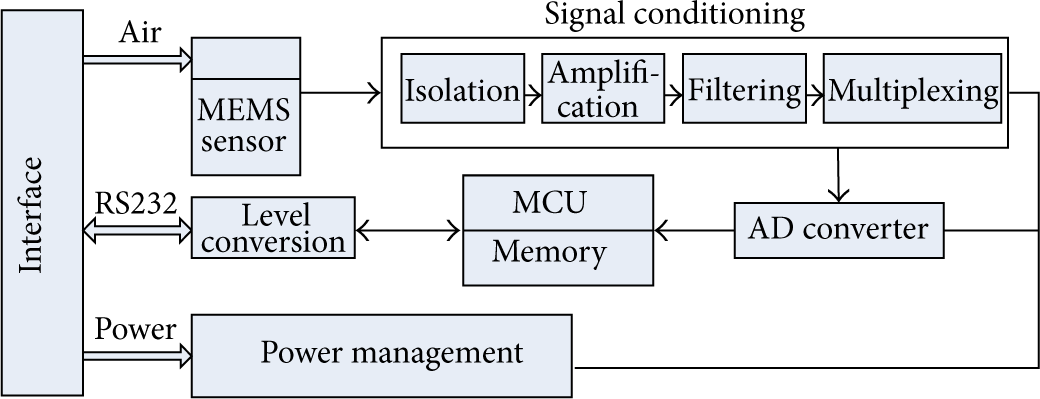
External sensors board schematics.

Physical figure of the external board.
2.2. Application on SHM
During the service period, some structure parameters closely linked to our daily life need to be monitored, such as bridge vibration acceleration, angle, strain, and deflection. A smartphone with emerging sensors can monitor some structure parameters, which can provide us with safety information and give us advice. With our monitoring software, people can do some tests by themselves, which needs less professional requirements. Based on the monitoring information and postprocessing data, the safety security will be provided for the users and reference for maintenance staff.
Moreover, in the event of an emergency (earthquakes, floods, and high winds), by judging structure state based on Mobile-SHM, people are guided to rescue and escape, while, in earthquakes, structural safety is diagnosed by sensors and advanced earthquake evaluation algorithm of Mobile-SHM, and then the reasonable shelters can be provided for people. In the process of earthquake rescue, the GPS unit of Mobile-SHM can be used for initial positioning for the trapped people, and the positioning information can be released to the rescue center by public telecommunication network. Even under the condition without signal for public network and GPS, the wireless local area network unit of the iPhone can communicate with the handheld wireless search device of the personnel for rescue. Then the trapped wireless positioning is built and provided to the rescue center.
In addition, wind power and direction can be determined in gale weather using mobile phone with an external sensors board, which provides reasonable suggestions for the people to resist wind and travel combined with the emergency procedures. In the coming flood, the safety of the dam is also judged quickly and conveniently by means of Mobile-SHM.
3. Experiments and Results
In order to verify the feasibility of the inner sensor of the iPhone and external sensors board based on the iPhone, numerous experiments, both in the laboratory and on an actual bridge, were conducted. The experiments and results are described as follows.
3.1. Experiment Comparison in the Laboratory
There are three experiments in laboratory to verify the feasibility of the inner sensors unit and external sensors board. They are swing test, acceleration comparison experiment on shaking table, and the cable force comparison of a cable model in laboratory. The details are as follows.
3.1.1. Swing Test
In order to validate that the gyroscope of the iPhone has the function of dynamic angle measurement, an inclination measurement comparison test is carried out using the iPhone and a wireless inclinometer in the pendulum experimental device.
Figure 4(a) shows the sensors on pendulum; as Figure 4(a) shows, the iPhone and the wireless inclinometer are placed in the center of the hanging basket of the pendulum for measuring the inclination of the pendulum [12]. The wireless inclinometer sends the real-time dynamic inclination data to the base station and the iPhone collects and stores the data in its own memory for further computation. Figure 4(b) shows the gyroscope collecting interface of the iPhone.
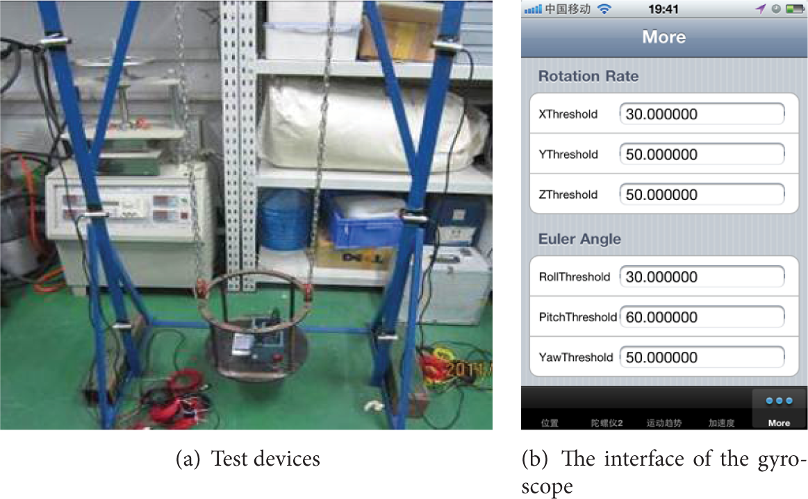
Swing test devices and interface on the iPhone.
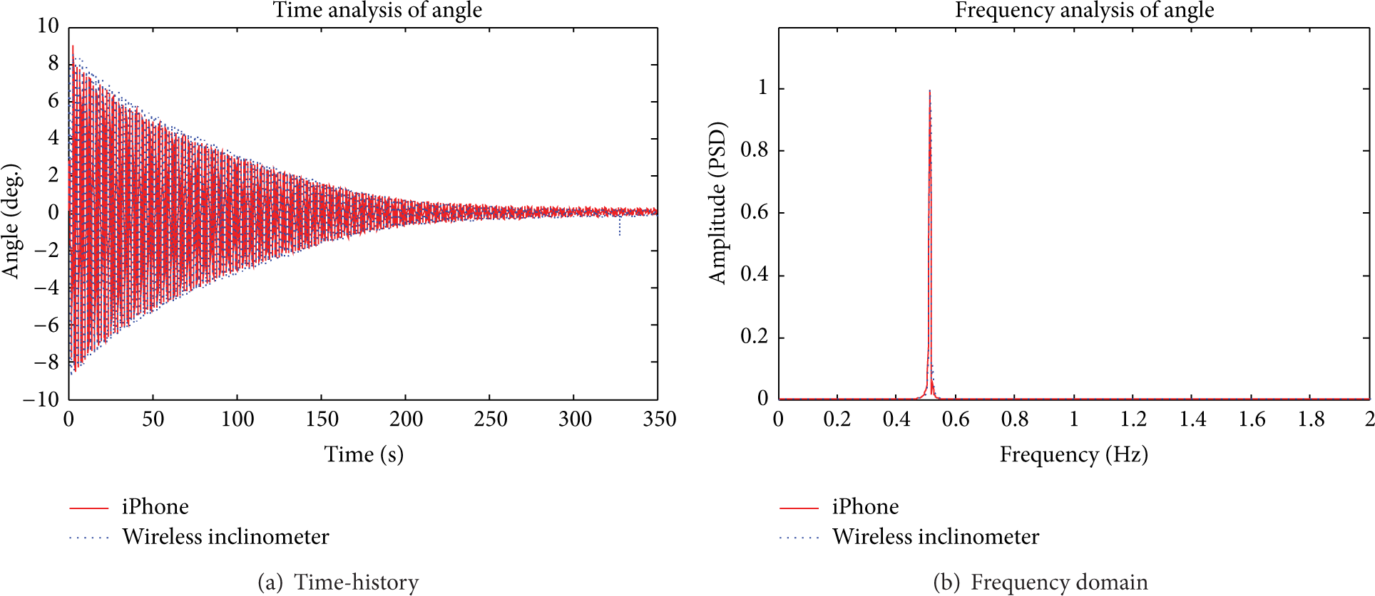
In the experiment, the pendulum's hanging basket is firstly set in equilibrium, and then people will start the Mobile-SHM software on the iPhone for the gyroscope collection function and the inclination acquisition of wireless inclinometer. Lastly, the basket will swing due to an external excitation.
The sample rates of the iPhone and wireless inclinometer are both 100 HZ; they collect angle data simultaneously until the pendulum goes to equilibrium. The experimental results are shown in Figure 5, which illustrates that data waveforms of the iPhone and the wireless inclinometer are coincident quite well in the time domain. On the other hand, the two first-order frequencies are both 0.515 Hz in frequency domain, which are equal to the natural frequency of the pendulum. By the above analysis, it is concluded that the inner sensor accelerometer of the iPhone meets conventional measurement requirements.
Experiment results.
3.1.2. The Acceleration Comparison Experiment on Shaking Table
In order to detect the accuracy of the mobile external sensor based on the iPhone, a vibration comparative experiment was carried out on a three-layer steel frame model with the vibration table shown in Figure 6.
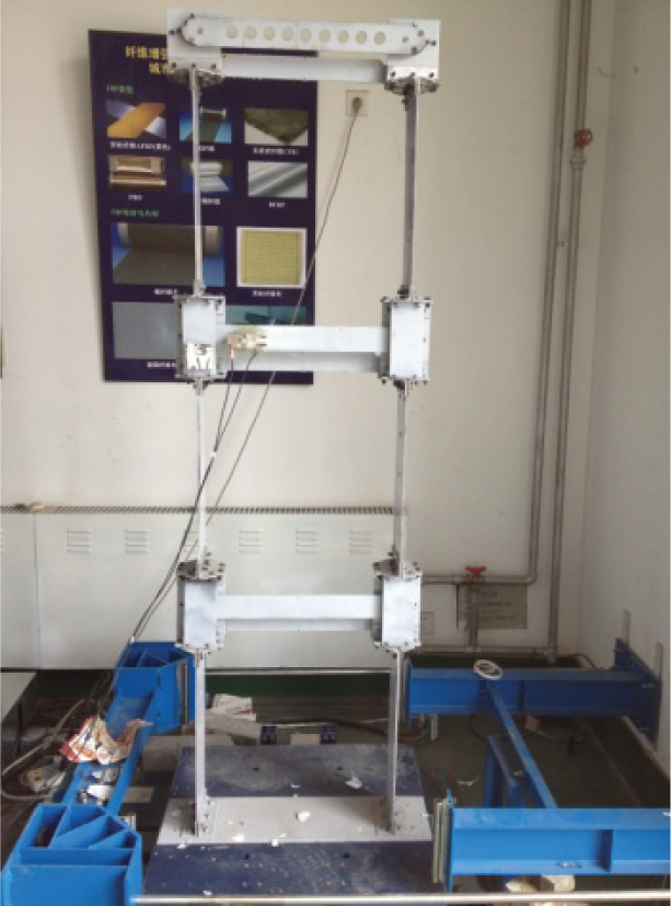
Three-layer steel frame model on the shaking table.
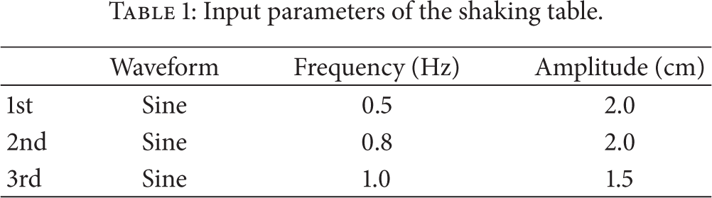
A three-story steel frame model was fixed on the horizontal shaking table, while its three dampers were consolidated. The weight of the steel frame is 50.3 kg, and that of the shelf used for the sensor's placement is 11.8 kg. The damper is 8 cm in diameter. The length, width, and height and thickness of each steel frame are
Input parameters of the shaking table.
The time-domain chart and frequency-domain chart of the 3rd test result selected from the three sets of comparative tests are shown in Figures 7 and 8.
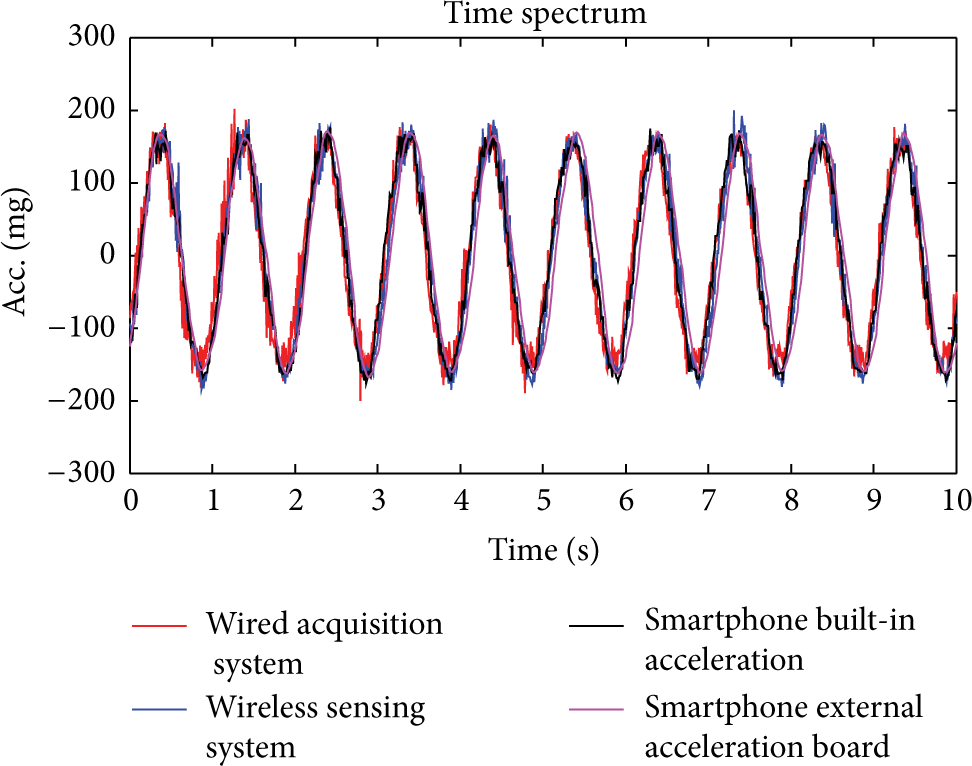
Time-domain comparison chart of the 3rd test.
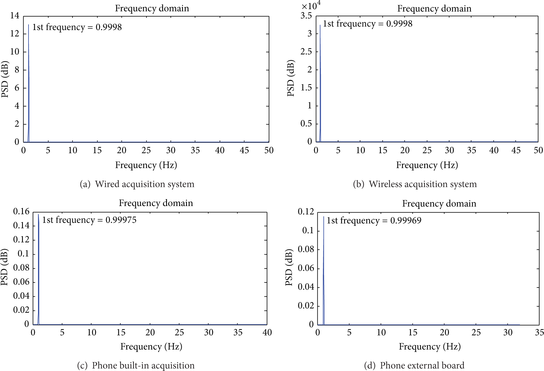
Vibrating frequency comparison chart of the 3rd test.
From the test results of the 3rd test, it can be seen that the time-history curves of four sensors are coincident, and the obtained vibration frequencies of four sensors are the same. Thus the precision of inner sensor and external sensors board can meet the measurement requirement.
The comparison results of the three tests are shown in Table 2.
The comparison results of three tests.
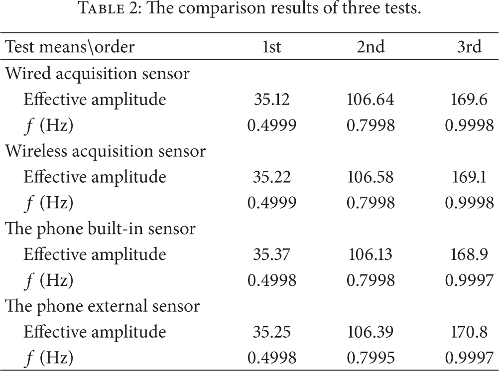
From Table 2, it can be seen that the effective amplitude and the vibration frequency are coincident among different sensors; the built-in sensor of the iPhone and external sensors based on the iPhone can meet the measurement requirement, which can be used in the vibration test.
3.1.3. The Cable Force Test in Laboratory
As the most important component of a cable-stayed bridge, the cable not only bears the bridge load, but also controls the internal force distribution of the entire bridge deck system. Therefore, the cable tension can be used as an important indicator of health status assessment of a cable-stayed bridge.
Cable force is easy to change because of the high concentration of stress corrosion, fatigue of the anchorage zone, storms, and other disasters. Therefore, the monitoring of the cable force is essential for the condition assessment of the cable-stayed bridge. In this test, the cable force is monitored using vibration method based on the iPhone accelerometer.
The vibration method to measure the cable force is widely used in the construction control and health monitoring of the cable structure. Its principle is based on the vibration theory of the tensioned string, and the relationship between the tension and natural vibration frequency of the cable is shown in the following equation [13] (without regard to the influence of stiffness and sag):

The cable model is in the Laboratory of the Institute of Bridge Engineering in Dalian University of Technology; the length l is 15.53 m and the linear density m is 3.95 Kg/m.
In order to verify the validity of the cable force test using smartphones, a force balance acceleration sensor was selected to compare the result of the inner and external sensor of the iPhone. The arrangement of sensors on cable is shown in Figure 9. Three tests were conducted repeatedly, and the results of test 1 were shown in Figures 10 and 11.

Arrangement of acceleration sensors on cable.

Acceleration curves of three sensors in test 1.

Power spectral density of sensors’ vibration data in test 1.
The cable is knocked, and the acceleration is collected by three sensors; the vibration data of sensors may draw out the frequency by FFT; finally the cable force can be calculated according to formula (1).
Figure 10 shows the acceleration curves of three sensors after knocking.
Figure 11 shows the power spectral density of the sensors’ vibration data in a knocking process. It can be seen that the power spectral density peak corresponding to each sensor is very clear, and the frequency interval between adjacent peaks is within acceptable ranges of error.
From Figure 11, the frequency difference can be obtained, and then the cable force can be obtained by formula (1); Table 3 shows the frequency difference and the cable force of three sensors in three tests.
Frequency difference and cable force of three sensors.

From Table 3, it can be obtained that the error between three sensors is small, and the results of three tests show the stability of three sensors. Compared with the mature force balance acceleration sensor, the inner acceleration of the iPhone and the external sensor based on the iPhone can meet the engineering monitoring requirements.
3.2. Cable Force Test on an Actual Bridge
3.2.1. Introduction of the Actual Bridge
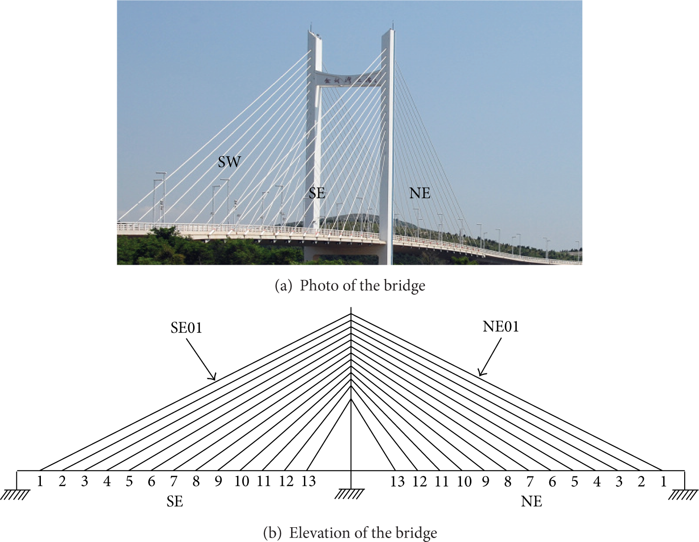
The bridge is a concrete bridge with one tower and double cable plane. The whole bridge length is 900 m, and the width of the bridge is 15.5 m–18.4 m. Each side has thirteen cables, and cables are numbered 1~13 from the longest to the shortest one. The photo of the bridge and the elevation of the bridge are shown in Figure 12.
The actual bridge.
3.2.2. The Test of Cable Force
(1) The Test of Thirteen Cables in the Southeast. As introduced above, there are thirteen cables of each side; in the first test, three iPhones are selected to test the cable force in the southeast. The iPhones are numbered as 1, 2, and 3. There are three people to fix the iPhone on the cable; each person controls an iPhone, respectively; that is, the first person fixed iPhone 1, the second person fixed iPhone 2, and the third person fixed iPhone 3. The parameters of cables and the arrangement of the iPhones are shown in Table 4. Take cable 13 as an example, and the field test photo of cable 13 is shown in Figure 13.
Cable parameters and the arrangement of the iPhones on the cable.

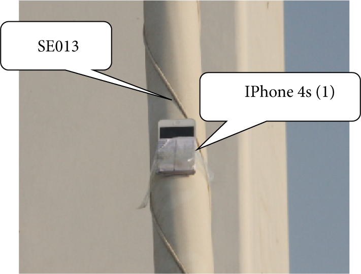
Field test photo of cable 13.
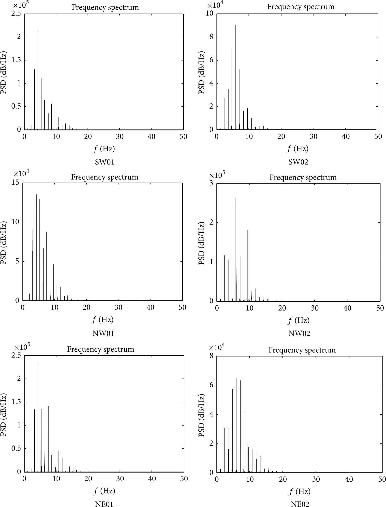
Several minutes are taken to test the cable force; the time-history curves of thirteen cables are omitted because of the length of the paper and the frequency spectra obtained by FFT are shown in Figure 14.

Power spectral density of each cable's vibration data.
From the above frequency spectrums, it can be seen that the frequency peaks of iPhone 1 and iPhone 2 are obvious, but the peak of iPhone 3 is not obvious, because the third person did not fix the iPhone on the cable firmly, which resulted in the third iPhone not being able to vibrate with the cable simultaneously, and the frequency difference is difficult to obtain from the frequency spectrum. Table 5 shows the frequency difference and cable force of each cable; for the above reason, the frequency differences of cable 3, cable 6, and cable 9 are difficult to obtain. But thirteen cables can be tested by three people in an hour; the monitoring efficiency can be improved greatly.
The frequency difference and cable force of each cable.

(2) The Comparison Test. In order to prove the feasibility of the inner sensor and external sensors board of the iPhone on the actual bridge, force balance acceleration sensor was selected to compare with them. The test arrangement was shown in Table 6; the inner sensor of the iPhone and force balance acceleration sensor were fixed on cable 1 in the southeast, and the external sensors board and force balance acceleration sensor were fixed on the cable 2 in the southeast. Take cable 2 as an example; the field test photo of cable 2 is shown in Figure 15.
The sensor arrangement of comparison test.


Sensors on cable 2.
The cables were knocked, and the acceleration was collected by the above sensors. And then the frequency spectrums are obtained by FFT; the frequency spectrums of two tests are shown in Figures 16 and 17.

Frequency spectrum of two sensors on cable 1.

Frequency spectrum of two sensors on cable 2.
The frequency difference and cable force obtained by different sensors of two cables are shown in Table 7.
Frequency difference and cable force obtained by different sensors.

From Table 7, it can be seen that the error between two sensors on a cable is small, and the comparison proved that the inner sensor of the iPhone and the external sensors board can meet the measurement requirements.
(3) The Test of the Boundary Cable of the Other Three Cable Planes. In order to know the force of the cables with the same length, two long cables of each side were selected to test by using the inner sensor of iPhone 1 and iPhone 2, which are the same as iPhone 1 and iPhone 2 in the first group test. In four cable planes, iPhone 1 tests cable 1 and iPhone 2 tests cable 2. The frequency spectrums are shown in Figure 18.
Frequency spectrums of boundary cables.
From the frequency spectrums shown in Figure 18, the frequency peak is clear, and the frequency difference of each cable can be obtained. The frequency difference of each cable is shown in Table 8, and the frequency difference of SE01 and SE02 obtained in test 1 is also shown in Table 8.
Frequency difference of boundary cables.

From Table 8, it can be seen that the frequency differences of the cables with the same length are approximately equal, and each cable plane is in a balance state. The using of the iPhone can get the cable parameter successfully; it is feasible on the application of cable force test. More importantly, an iPhone, as a monitoring tool, does not need any other devices and wires and needs less professional requirements. And the interactive interface makes it is easy to operate; convenience is the biggest advantage for field monitoring.
4. Conclusion
A new idea of SHM is presented in this paper: Mobile-SHM based on smartphones is proposed, which concludes inner sensors unit of the iPhone and the external sensors board based on the iPhone. Some tests were conducted to verify the feasibility of Mobile-SHM; compared with the mature sensors, two sensing patterns can monitor the same structure parameters successfully. Moreover, using them is convenient and effective, and then some reasonable suggestions can be made for reference in judging the security status of bridge and other structures based on the obtained parameters. Moreover, the interactive interface of the software makes it is easy to operate; using it needs less professional requirements. Thus people can obtain some structure parameters by themselves; it can play a guiding role for people's daily lives and promote the widespread application of the SHM system.
For the popularity of smartphones and advantages of wireless long-distance transmission, the system can be used widely in other applications, in addition to being applied in the cable force test. Applications of the method in other applications will be discussed in detail in the future work.
Footnotes
Conflict of Interests
The authors declare that there is no conflict of interests regarding the publication of this paper.
Acknowledgments
Thanks are due to the financial supports of the National Natural Science Foundation of China (51278085, 51221961) and the Key Projects in the National Science & Technology Pillar Program during the Twelfth Five-Year Plan Period (2011BAK02B02).