
Abstract
Industrial wireless sensor networks (IWSNs) can provide wireless communication for the control system and have therefore received considerable attention. However, network-induced delays or packet losses, among other issues, significantly degrade the performance of IWSNs and can even destabilize an entire system. In this study, a predictive compensator, a modified linear quadratic regulator (LQR) compensator, and a combination of both compensators were proposed to mitigate the effects of unpredictable packet loss in an IWSN. The control system applying the three proposed compensators was simulated under various condition of packet loss using Matlab Simulink and Truetime. An inverted pendulum was used as the object of the controller. Simulation results showed that, among the three compensators, the combined compensator works best in compensating for the packet loss in both forward and backward channels of the control system.
1. Introduction
Recent advances in sensor technology have allowed for wireless communication technologies to be introduced not only for use in homes or offices, but also for use in a variety of industrial settings, including in factories, for industrial monitoring, or for control networks. IWSN systems offer outstanding advantages over wired control systems such as greater flexibility, ease of installation, and cost savings. In addition, IWSNs can be installed in environments where the equipment might be exposed to chemicals or vibrations [1]. However, the implementation of IWSNs is subjected to obstacles resulting from the fundamental properties of their wireless medium. Variable packet loss may result in system inconstancy which renders control systems over IWSNs unreliable. Therefore, the control systems that offer adequate performance must provide strict adherence to both real-time and reliability specifications. Otherwise, physical deterioration may result in inadequate operation. As a result, the optimum operation of IWSNs depends on developing a method that can manage packet loss [2].
The operation of wireless networked control system (WNCS) has been analyzed in [3–6]. Reference [3] introduced a short analysis of the basic features of wireless networked control system along with techniques and protocols used to deal with delay induced in the network. Reference [4] presented fundamental ideas for wireless control of an inverted pendulum, which is the representative system that is considered for the methods proposed in this study. In [5, 6], the different control aspects for such a system can be analyzed by modeling the entire system with mathematical expressions. References [7–16] proposed different methods to deal with the packet loss in WNCS. Reference [7] investigated the performance of a PIDPLUS controller over a WNCS. The performance of the PIDPLUS controller was found to be acceptable under moderate packet loss rates, but the performance dramatically decreased at higher loss rates. Reference [8] proposed a time-triggered architecture to manage the uncertainty in the transmission time and to improve the real-time performance of the IEEE 802.15.4 standard. In [9], the issues of controlling multiple plants over a shared wireless network were explored. References [10–15] applied different PID and LQR algorithm for control system over unreliable wireless network link. In [16], the packet loss in the forward channel is compensated by using a proposed predictive compensator. The performance of the control system in [16] was also improved by using LQR algorithm in the feedback loop for generating the optimal inputs for the PID controller. The system was tested in WNCS under a range of packet loss rate and a short discussion on the system performance was given.
So far, the designs and analyses of control systems in existing literatures mainly focused on controlling over wired network. Some studies also tried to solve the problem of packet loss in WNCS but their methods relied on the 802.11, which is not optimally designed for control system as the 802.15.4. In addition, most of these methods only compensate for the packet loss in either forward or backward channel.
In this study, a combination of a predictive compensator and a modified LQR compensator was proposed to compensate for the packet loss in both forward and backward channels of the control system over 802.15.4 IWSN. The predictive compensator was designed to compensate packet losses in the forward channel by suggesting replacement commands sent from the controller. LQR compensator was originally designed for wired network control system without considering the packet loss. In [16], the original LQR was examined in wireless network control system under various condition of packet loss. Since the LQR did not compensate for the packet loss in the backward channel, the system performance in [16] showed its degradation when packet loss happened. In this paper, the proposed LQR was modified to compensate the packet losses in the backward channel. By considering the packet loss rate, the modified LQR estimates the optimal matrix and the plant's state to find the optimal control value.
In order to test the proposed compensators, an unstable and nonlinear inverted pendulum was used as the object of the controller. The simulation was run under various conditions of packet loss rate using Matlab Simulink and Truetime. The results showed that, with the proposed compensators, the control system can tolerate high packet loss rates. It was also shown that, among the three compensators, the combined one yields the best performance.
2. Background
2.1. Overview of Control over IWSN
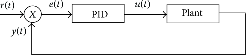
The basic schematic for control over IWSN is shown in Figure 1 [17]. In such a system, sensor nodes are responsible for monitoring parameters including vibration, temperature, pressure, and power quality. These data are then wirelessly transmitted to a reference node that analyzes data from all sensors. A control signal based on the feedback signal is sent to the actuator, which enables the plant to adjust, repair, or replace equipment before efficiency drops or even a complete failure occurs.

The general structure of controlling over IWSN.
2.2. Control Method: PID Controller
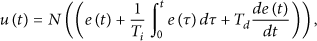
Although PID controllers were described in control theory many years ago, they are still used for current industrial applications because their structure can be easily adjusted to be adopted in different systems. The block diagram of a closed-loop PID control system is shown in Figure 2.
Block diagram of closed-loop PID scheme.
The control command
2.3. Mathematical Model of an Inverted Pendulum
In this paper, an inverted pendulum, a classic problem in control theory, is used for testing the performance of the control system. The diagram of an inverted pendulum is illustrated in Figure 3 [12]. A pendulum rod is assumed to be massless, and its hinge is frictionless. The mass of the cart and the point mass at the end of the rod are denoted by M and m, respectively. The length of the rod is denoted by l.
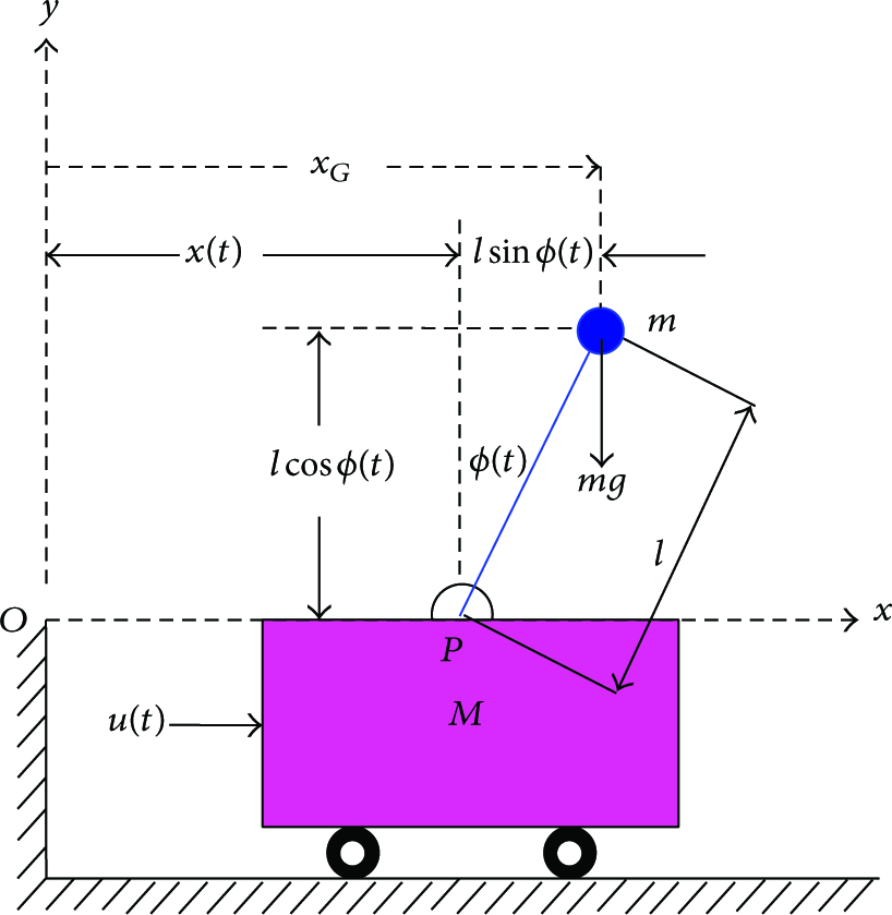
Diagram of an inverted pendulum.
The control objective is to maintain the pendulum in upright position. To do that, the controller needs to move the cart back and forth to generate a torque on the pendulum, thus keeping the pendulum in upright position. Depending on the angular displacement of the pendulum as well as other parameters such as the point mass and the cart mass, the controller will determine the proper force to apply to the cart.
The dynamics of the inverted pendulum is described by (2) [12]. Consider

According to [6], we have a transfer function

3. Proposed Schemes
3.1. System Description
Figure 4 shows the block diagram of the control system over IWSN simulated using Matlab/Truetime. The pendulum cart system was stabilized by using a PID controller while the control and feedback signals are transmitted over the IWSN.

IWSN based control system simulated using Matlab/Truetime.
When a system operates in an IWSN, data packets sent between the sensors, controllers, and actuators may be lost. With such an occurrence, the control system can be broken and an additional entity would have to compensate for the packet loss. Depending on how and when the packet loss occurs, this problem may be difficult to handle.
The issue under study in this paper is how to compensate for the effect of packet loss on control over IWSN. The solution that is proposed here is to overcome packet loss in the network by placing a compensator on the plant side or the controller side of the IWSN based control system. In order to evaluate the performance of the PID controller, the control system simulation was run under various conditions of packet loss.
3.2. The Three Proposed Compensators
3.2.1. Predictive Compensator in Forward Loop
With the uncertainty of the wireless channel, the control command can be lost when transmitted from the controller to the plant. The first proposed compensator deals with the packet loss in the forward channel by suggesting replacement commands in case of packet loss. This compensator can be added to the plant without any changes in the structure of the existing IWSN.
Predictive algorithm has been used extensively for traditional wired networked control systems. In this paper, the predictive algorithm is used for compensating packet loss in IWSN based control system. When packet loss happens, instead of using the last command or a specific constant command, the compensator suggests a replacement command based on historical data of the system.
The block diagram of the controller with the predictive compensator is shown in Figure 5. The feedback

Compensator at a forward loop of the IWSN control system.
The replacement command value is given as

Figure 6 shows the controller with the predictive compensator simulated using Matlab/Truetime. It can be seen in Figure 6 that the feedback

IWSN based control system with predictive compensator simulated using Matlab/Truetime.
3.2.2. Modified LQR in Feedback Loop
It is clear that packet loss can occur at either the sensor-controller side or the controller-actuator side in control system over IWSN. Modified LQR can also be used at the feedback loop to provide another approach that reduces the effects of packet loss. The concept of the proposed method is described in Figure 7. The compensator is placed before the controller. When packet loss occurs in the backward channel, the compensator will estimate the lost feedback value and give it to the controller for generating the command. In Figure 7,

Compensator at backward loop of the IWSN control system.
According to [4, 10, 12, 16], traditional LQR observes the states of the control system and generates the optimal control decisions. However, it does not consider the packet loss rate. In the modified LQR, the packet loss is taken into account when calculating the value of the feedback vector K.
At backward communication, the packet loss can be modeled as follows:

Considering the discrete-time linear system, it can be supposed that

At the compensator based modified LQR, we can get the matrix

The optimal estimated value

Controller produces optimal control value
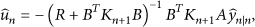
Figure 8 shows the simulation IWSN control system with modified LQR compensator using Matlab/Truetime. Based on the Matlab manual [19], the modified LQR compensator was created by creating a Matlab M-file with specific functions and embedding it to a modified LQR object. As can be seen from Figure 8, the information required for the controller to calculate the control value includes the position of the cart

IWSN based control system with modified LQR compensator simulated using Matlab/Truetime.
3.2.3. Combination of Predictive and Modified LQR Compensator on Both Sides
The final proposed compensator in this paper is the combination of the two compensators described in the previous sections. This proposed combined compensator which includes a predictive compensator at the forward loop and a modified LQR at the backward loop will compensate for packet losses occurring in both channels. Figure 9 shows the block diagram of the proposed combined compensator. As shown in Figure 9, the input for the controller includes the position of the cart

IWSN based control system with combined compensator simulated using Matlab/Truetime.
4. Simulation and Discussion
The control system with an inverted pendulum as the object for the controller was simulated using Matlab/Truetime. Based on [6], the typical parameters of an inverted pendulum were used: mass of the cart (M) set at 0.6 kg, mass of the pendulum (m) set at 0.25 kg, length of pendulum (l) set at 0.3 m, and inertia of the pendulum (I) set at 0.0054 kg·m2. The friction coefficient of the cart and the pole rotation were assumed negligible. The values of PID gains in our paper were chosen between reasonable ranges to yield the reasonable performance of the control system. With the value of P, D, and I ranging between [0~10], [0~100], and [−10~10], respectively, the reasonable performance of the control systems was obtained when
After calculating,
In the modified LQR, the input weighting R is chosen as 1, matrix
In this paper, Zigbee was used for the wireless communication with the following parameters.
Frequency: 433 MHz. Transmission bit rate: 19.2 kpbs. Transmit power: 20 dBm. Receiver signal threshold: −10 dBm.
4.1. System Response
In our study, the packet loss rate (
As explained earlier, when the balance of the pendulum is affected, the controller calculates the proper force to be applied to the cart to make it move back and forth, thus keeping the pendulum in the upright position. When packet loss happens in the wireless forward channel, the actuator will not receive the control value (i.e., the force value) sent from the controller and the pendulum system becomes unstable as a result. On the other hand, if packet loss takes place in the wireless backward channel, the controller will not receive the feedback which is required for calculating the control value and the pendulum system becomes unstable too. With the aid of compensators proposed in this paper, the pendulum system can maintain its stability in both cases of packet loss.
To compare the performance of the controller with the three proposed compensators in different condition of packet loss, a simple reference input was given to the three controllers and the output responses were taken as the cart position. Because bringing the inverted pendulum back to the upright position requires precise movements of the cart, the reference input used for the comparison simply commands the cart to move back and forth to certain positions at certain points of time. The performances of the controllers are evaluated depending on how well the controllers can track the reference commands.
Figures 10, 11, and 12 show the responses of the three control systems with proposed compensators: prediction, modified LQR, and combination of prediction and modified LQR in different conditions of packet loss: 10%, 30%, 50%, and 70%. The same reference input is given to the controllers in the three figures: the cart is commanded to move to the position 1 m ahead and stay there in 20 seconds and then move back to the original position and remain there. The output responses were taken as the position of the cart moving under these commands. It can be seen in each figure that, for the same system, the responses corresponding to different levels of packet loss are different. In addition, for the same level of packet loss, the response of different control systems is different because the compensation mechanisms applied in these systems are different as can be seen in the three figures.
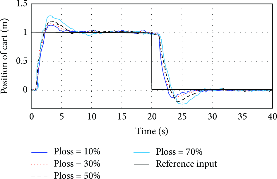
Response of the control system with predictive compensator.

Response of the control system with modified LQR compensator.

Response of the control system with combined compensator.
Figure 10 shows the reference input and response of the controller with predictive compensator at 10%, 30%, 50%, and 70% of packet loss rate. It is shown through the figure that the performance clearly deteriorates as the packet loss rate increases. There are more overshoot and undershoot in the response corresponding to 70% of packet loss than those of 50%, 30%, and 10% of packet losses.
Figures 11 and 12 show the reference input and the response of the controllers with modified LQR and predictive combined modified LQR compensator in 10%, 30%, 50%, and 70% packet loss rate. In both figures, the performance of the controllers degrades when the packet loss increases. In Figure 11, the response at 70% of packet loss is slower than that of 50%, 30%, and 10% of packet losses. The same applied for Figure 12 even though the differences are smaller.
The differences in the performance of the three proposed compensators can be seen through Figures 10, 11, and 12. In Figure 10, the system quickly responses to the reference input, but the overshoot and undershoot are high. In Figure 11, there is neither overshoot nor undershoot. Nonetheless, the system responds very slowly to the reference input. It can be seen that it takes less than 3 seconds for the cart in Figure 10 to reach the target position. In Figure 11, the cart takes nearly 10 seconds to reach to the target position in the case of 70% of packet loss.
The controller with the combined compensator in Figure 12, however, shows the surpassing performance compared to those on Figures 10 and 11. While there is neither overshoot nor undershoot, the cart reaches the target position with small latency. Furthermore, the responses corresponding to different levels of packet losses shown in Figure 12 are close to each other comparing to those in Figures 10 and 11. This is because the combined compensator works more effectively and thus does not make the system performance deteriorate as the rate of packet loss increases.
4.2. Integral of the Absolute Magnitude of the Error (IAE)
In this section, the system was simulated with the control objective to bring the pendulum to upright position. The simulation was run under various conditions of packet loss, and the mean IAE in each condition was calculated. The error was defined as the difference between the reference value and feedback value.
Figure 13 shows the comparison between the three compensators. For a packet loss rate smaller than 70%, the modified LQR compensator yielded the lowest performance with a high IAE because of its slow response. For higher packet loss rates, the mean IAE of both the predictive and modified LQR compensator gradually increased because of the instability of the system. In particular, when the packet loss rate exceeded 90%, the control system with the predictive compensator collapsed as shown in the rocketing increase of mean IAE. While the two remaining compensators can thrive at high packet loss rates, the combined compensator proved to be superior. In all of the cases of packet loss, the control system using the combined compensator remained stable with relatively small increase in mean IAE when the packet loss increased as shown in the figure.

Mean IAE of three methods.
4.3. Response of Cart
For the simulation in this section, the packet loss rate was set at 50%. Figure 14 shows the position of the cart moving under commands from the controller. Because the cart was commanded to move back and forth to bring the pendulum to upright position, the position of the cart would not become stable until the pendulum became stable in upright position. Figure 14 shows that the control system with the three proposed compensators was able to fulfill the control objective at 50% of packet loss.
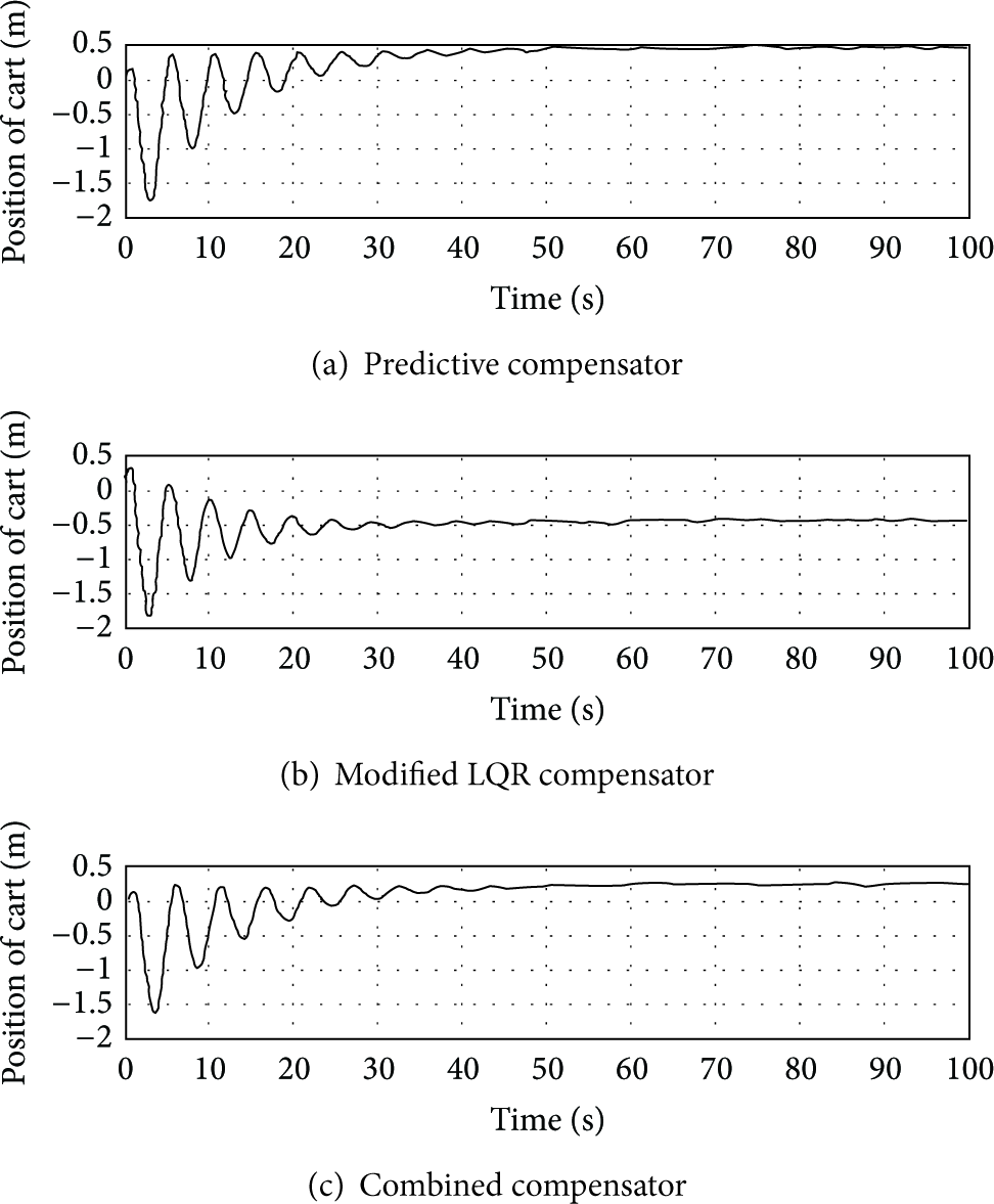
System response corresponding to the three compensators with 50% of packet loss.
With the predictive compensator, the stable position of the cart (i.e., the position of the cart when the pendulum obtained its stability in upright position) was at 0.4 m from the original position as shown in Figure 14(a). With the modified LQR compensator, the stable position of the cart was at 0.5 m as shown in Figure 14(b). The combined compensator demonstrated its superior performance with the stable position cart being at 0.2 m. This simulation provided a clear explanation for Figure 13 which showed that, at a 50% packet loss rate, the mean IAE of the modified LQR compensator is highest while that of the combined compensator is lowest.
Note that in this simulation the packet loss rate was only 50%. At this level of packet loss, the mean IAE of three compensators was different by small margins as shown in Figure 13. Therefore the movements of the cart corresponding to three compensators were quite similar as shown in Figure 14. At higher packet loss rate, the stable position of the cart corresponding to the three compensators would be much more different since the differences in the mean IAE of the three compensators were much larger.
5. Conclusion
Control system over IWSNs should be able to manage unreliable transmission of the control value from the controller to the plant as well as the feedback from the plant to the controller. In this paper, three compensators were proposed to compensate for the packet loss in IWSN based control systems. The first proposed compensator applied a predictive algorithm to generate replacement data for the lost control data in the forward channel. The second proposed compensator used a modified LQR method to compensate for the packet lost in the backward channel. The third proposed compensator is the combination of the predictive and modified LQR compensator which can compensate for the packet loss in both channels. To evaluate the performance of the proposed compensator, we simulate the system using Matlab Simulink and Truetime. The inverted pendulum was used as the object of the control system. The simulation was run under various conditions of packet loss. The simulation results showed that the three proposed compensators all could help the control system thrive at high packet loss. The combined compensator brought about the best performance among the three proposed ones. However, applying the combined compensator might be costly since it required many elements assembled at both sides of the control system.
Footnotes
Conflict of Interests
The authors declare that there is no conflict of interests regarding the publication of this paper.
Acknowledgment
This research was supported by Basic Science Research Program through the National Research Foundation of Korea (NRF) funded by the Ministry of Education, Science and Technology (no. 2012R1A1A2042995).