
Abstract
Radio frequency identification (RFID) provides a contactless approach for object identification. If there are multiple tags in the interrogation zone of a reader, tag collision occurs due to radio signal interference. To solve tags identification collision and improve identification efficiency in RFID system, a flood division anticollision (FDAC) algorithm has been presented. Firstly, the algorithm launches an estimation of the number of tags and according to the estimation result decides whether a flood diversion processing needs to be started or not. Secondly, when the flood diversion processing needs to be done, all tags are grouped and assigned to different models in which the tags are to be processed and identified in parallel. Thirdly, in the identification processing, for reducing data transmission, the reader needs only to send a three-dimensional-vector command to tags, tags respond to the command with part of collision-bit parameters, and stack and queue are adopted to store precious request command and tags' ID to avoid repeatedly transmitting them between the reader and the tags. Simulation experiment results show that FDAC is superior to the dynamic frame slotted (DFS) Aloha algorithm, the binary-retreat tree algorithm (BRT) and the dynamic binary-search tree (DBST) algorithm, in the performances of data bits transmission, identification time delay, and energy consumption by the reader.
1. Introduction
Radio frequency identification (RFID) is an automatic identification scheme which is a contactless, low power, and low cost wireless communication technology. In recent years, a still growing number of articles have developed the RFID in technology and engineering, such as the cooking and dietary management system, the meat freshness monitoring system, the smooth medical service, the equipment management system via the wireless sensor network, the wireless monitoring of household electrical power meter, the system for tracking and behavior analysis of small animals [1–3], the intelligent traffic flow control system, and the building access. In addition, more and more novel RFID sensing systems have been designed to satisfy some special requirements in engineering, and many effective measures have been proposed to improve the technology on RFID [4–7].
An RFID system consists of a reader and one or more tags. Tag is attached to object; a reader recognizes an object by issuing RF signals to the attached tag [8]. RFID tag contains two major parts. One is an integrated circuit for storing and processing information, modulating, and demodulating an RF signal and perhaps other specialized functions. The second is an antenna to receive and transmit the signal. In an RFID system, every tag has a unique identification code (ID) [9]. The length of ID may be different in different RFID standards.
While a tag and a reader are close enough, they can communicate with each other. For such a situation, we say that the tag is in the interrogation zone of the reader. To figure out which tags are within the interrogation zone, a reader initiates an interrogation procedure to request tags to send back their IDs. When multiple tags respond to the reader simultaneously, tag collisions occur and no tag can be identified by the reader successfully [10]. The RFID system will become very low efficient and high power consumption while tag collision occurs frequently [11, 12]. Reducing the tag collisions and signal denoise [13] are often employed to improve efficiency of the RFID system.
How to reduce tag collisions to speed up the identification procedure and lower energy consumption is thus important. There are several tag anticollision protocols proposed for reducing tag collision. To achieve this goal of efficient tag reading, various tag reading protocols have been proposed in the literature. They are classified into two categories: probabilistic protocols and deterministic protocols. Probabilistic protocols are based on the Aloha framework. In Aloha-based algorithms, tags respond to the reader by transmitting IDs in a probabilistic manner. For example, in slotted Aloha algorithms, the whole interrogation procedure period is divided into several time slots, and each tag randomly chooses a time slot for transmitting its ID to the reader. Aloha-based algorithms are simple; however, they have the tag starvation problem that a tag may never be successfully identified because its responses always collide with others [14–17].
Deterministic protocols are based on binary tree framework where each root-to-leaf path represents a unique tag ID. The basic idea of the binary tree-based algorithms is to repeatedly split the tags encountering collisions into subgroups until there is only one tag in a subgroup to be identified. The binary tree-based algorithms do not have the problem of tag starvation [18].
Both of the above category algorithms have their advantages and shortcomings [14]. This paper presents a flood division anticollision (FDAC) algorithm, which uses the flood division idea and integrates the advantages of both Aloha-based algorithm and classical binary tree-based algorithm. FDAC firstly estimates the number of tags and then deals with tags by parallel processing with flood diversion idea according to the estimated result. FDAC makes the reader only send one three-dimensional-vector command, and then tags respond to the command with part of collision-bit parameters, which makes both read-write operations and collision processing work simultaneously and the read-write time can be ignored. We simulate and analyze FDAC and compare it with other algorithms in terms of the performances of data transmitting, time delay, and energy consumption.
The rest of this paper is organized as follows. Some related work is introduced in Section 2. In Section 3, we describe FDAC by elaborating the concepts and mechanism of anticollision in the RFID system. In Section 4, we simulate and analyze FDAC and compare it with related algorithms. And finally, conclusion is drawn in Section 5.
2. Related Work
Almost all of the tag reading protocols are classified into two types: probabilistic protocols and deterministic protocols; the former use probabilistic algorithm and the latter use deterministic algorithm sometimes which may be a hybrid of the two type algorithms [16].
2.1. Probabilistic Algorithm
Aloha-based protocols are classical probabilistic algorithms, which try to stagger tag response times in a probabilistic manner to reduce collisions. There are several variants of Aloha-based protocols, such as classical Aloha (CA) protocol, slotted Aloha (SA) protocol, frame slotted Aloha (FSA) protocol, and dynamic frame slotted (DFS) Aloha protocol [19]. In these protocols, each tag reading round comprises three phases. The first phase is the broadcast phase, where the reader broadcasts the frame size to all tags. Frame size refers to the number of time slots available in a frame [20]. The second phase is the transmission phase, during which each tag randomly chooses a time slot within the frame and transmits its ID number. If more than one tag chooses the same time slot, their transmissions collide and the slot will ultimately be wasted. A slot is also wasted when none of the tags choose it for transmitting their IDs. Only those slots that are chosen by exactly one tag each end up actually being used and such slots are also referred to as successful slots [21]. The third phase is the acknowledgment phase, wherein the reader informs a tag if its transmission was successful or not. While the aforesaid working is common for all the probabilistic protocols, they differ in terms of the way in which they choose the frame size and the way in which they choose the tags that respond in a given round [22].
In classical Aloha protocol, while receiving the reader's interrogation request, each tag in the interrogation zone independently chooses a random back-off time and responds with its tag ID to the reader at that time. If an ID is received by the reader without collision, it can be identified properly and acknowledged by the reader. A tag with acknowledged ID will stop responding to the reader. On the other hand, an unacknowledged tag will repeatedly select a random back-off time to send its ID until it is identified and acknowledged by the reader [23].
In the slotted Aloha protocol, the random back-off time must be a multiple of a prespecified slot time. If collisions occur in a slot, the reader will notify the colliding tags to reselect a response time randomly. As it is shown, the performance of SA is twice that of CA since there is no partial collision of tag ID responses in the former protocol [24].
The frame slotted Aloha protocol is similar to SA. However, to limit the response time, FSA divides the whole interrogation procedure into a set of frames. Each frame has a fixed number of time slots, and a tag sends its ID to the reader in only one randomly chosen slot during a frame period. In FSA, when collisions occur, FSA adopts the avoiding strategy which is waiting for the next round to send response again. The efficiency of FSA very closely related to the number of tags. According to one statistic, lots of time slots are not fully utilized when the number of tags is less than the number of time slots which results in a very low efficiency of FSA. While the two numbers are approximately equal, the maximum efficiency is only approximate to 36.8%. Once the number of tags is greater than the number of frame time slots, collision increases significantly and the efficiency fell sharply [25].
The dynamic frame slotted Aloha protocol tries to eliminate the drawback by dynamically adjusting the frame size according to the estimated number of tags. It has better performance than SA and FSA. But it needs many communication rounds to optimize the frame size before the identification process. Under the assumption that the tag IDs are with the same series in production (i.e., tags have the continuous tag ID numbers), [22] proposed a lottery frame protocol to reduce the number of communication rounds with the help of the geometric distribution hash function. Although DFS improves the tags identification efficiency by dynamically changing the frame time slot, its efficiency has not been satisfactory.
In general, probabilistic algorithms are simple and have fair performance. However, some probabilistic algorithms have the tag starvation problem that a tag may never be identified when its responses always collide with others' or need many data bits transmitted in the communication rounds [26].
2.2. Deterministic Algorithm
Tree-based (TB) protocols are classical deterministic algorithms, which rely on tag IDs to repeatedly split colliding tags into subgroups until there is only one tag in a subgroup to be identified successfully. The query tree (QT) protocol and the binary tree (BT) protocol are two representatives of tree-based protocols [27].
In the query tree (QT) protocol, a reader first broadcasts a bit string S which has a specified length. The tag with an ID whose prefix matches with S will respond with its whole ID to the reader. If only one tag responds at a time, the tag is identified successfully. But if multiple tags respond simultaneously, the responses collide. In such case, the reader appends string S with bit 0 or 1 and broadcasts again the longer bit string. In this manner, the colliding tags are divided into two subgroups. If there is only one tag in a subgroup, it can be identified successfully. The reader keeps track of the request strings needed to broadcast with the help of a stack and perform tag identification procedure until all tags are identified [28]. QT does not have the tag starvation problem and its identification time delay is affected by the distribution and the length of tag IDs. Specifically, if the tags have long and continuous IDs, the request bit string will grow very quickly for identifying all tags. The delay time of the identification procedure will then increase significantly [29].
In the binary tree (BT) protocol, while receiving a reader's interrogation request, each tag responds with the first bit of its tag ID. The reader then records and broadcasts 1 (resp., 0) if the received bit is 1 (resp., 0 or a colliding signal). Only the tags with the first bit being 1 (resp., 0) will respond with its next ID bit; other tags will go into a sleep mode [25]. The above procedure will be repeated bit-by-bit until the last ID bit is reached. The reader can then identify and mute one tag and reset tags in the sleep mode to go through the interrogation procedure from some ID bit position. The bit-by-bit procedure is performed recursively and all tags can be identified. BT requires tags to be equipped with writable on-tag memory so that tags can keep track of the inquiring bit position [30, 31].
In recent reference, there are three improved variants of the binary tree protocol, that is, binary-search tree (BST) protocol, binary-retreat tree (BRT) protocol, and dynamic binary-search tree (DBST) protocol. BST adopts a recursive method to perform tags identification, in which all ID bits of a tag are used as transmitting parameters in the recursive process. And after finishing each tag's identification, the system will repeat sending the command used in the last time identification, where sometimes the command may not be useful. So, the disadvantage of BST is too much information needed for transmission which leads to low identification efficiency [32]. In BRT, the data structure technologies such as stack and queue are used to store and remember the previously used commands which will only be imported from the stack and queue while they need to be used again. So, the use of the data structure technologies, in part, makes BRT reduce the number of times of tags identification and the amount of information that needed transmitting [26]. In DBST, the tag ID is divided into two parts: known part and unknown part. For example, the tag ID has n bits; bit 1 to bit
2.3. Energy Consumption of RFID System
RFID systems consist of a reading device called an RFID reader and a finite number of tags. RFID systems can be divided into two classes: active RFID systems and passive RFID systems. The readers in both active and passive RFID systems have their own batteries. In an active RFID system, all tags are active tags which are provided with energy by their own batteries. In a passive RFID system, all tags are passive tags which have no battery and rely on RF energy transferred from the reader [34]. The energy consumed by the reader and a tag is an important issue that affects battery life time of mobile reader and active tags [35]. This issue has a twofold cause: on the one hand, the radio transceiver implies a higher power consumption compared to the other components of the embedded device; on the other hand, the communication phase is associated with phenomena such as collisions, overhearing (i.e., listening of messages addressed to another node), overemitting (i.e., transmission of data to a node that cannot receive them), and idle listening (i.e., listening to the channel in absence of communications), which substantially reduce the nodes battery [11]. To evaluate and reduce energy consumption, many works have been presented in the literatures [34, 36, 37]. Most of these works are mainly focused on energy evaluating or saving solutions on the level of anticollision protocols. In recent researches [11, 38, 39], Catarinucci et al. had proposed the most effective method by combining new MAC protocols with hardware solutions to further reduce the node's power consumption in wireless sensor networks.
3. The Proposed Algorithm
3.1. Idea of the Proposed Algorithm
Both DFS and BRT have their respective advantages. For example, the DFS algorithm is simple and rapid when tags are less and deterministic, and the BRT algorithm also has good identification efficiency because it utilizes data structure to reduce the number of times of tags identification and the amount of information that needs transmitting. In this paper, we try to utilize the advantages of both DFS and BRT by performing a novel method which is a hybrid algorithm of DFS and BRT. The flood division method is suitable for being used to parallel processing the unidentified tags, especially while the number of tags is large and nondeterministic. We call this method a flood division anticollision (FDAC) algorithm.
FDAC comprises three phases. In the first phase, FDAC first starts a simple estimation with the collision-bits detecting method to estimate the number of collision tags. Then, FDAC judges whether an accurate estimation needs to be done or not according to the simple estimation result. If the number of collision tags is greater than a predefined threshold, an accurate estimation process will be started. In this case, all collision tags are flood-divided and distributed into multiple modules automatically, in which the collision tags are processed in parallel. In the third phase, every module takes process and identification for all assigned tags with stack storage, queue storage, back strategy, collision-bit tracking technologies, and so forth. In the process, the reader only needs to send a three-dimensional-vector command, and then the tags respond to the command with part of the collision-bit parameters. Finally, the IDs of all successfully identified tags will be saved into a data structure-queue, and the operation of read-write for the tags is performed under the control of the processing center. The process of FDAC is shown in Figure 1.
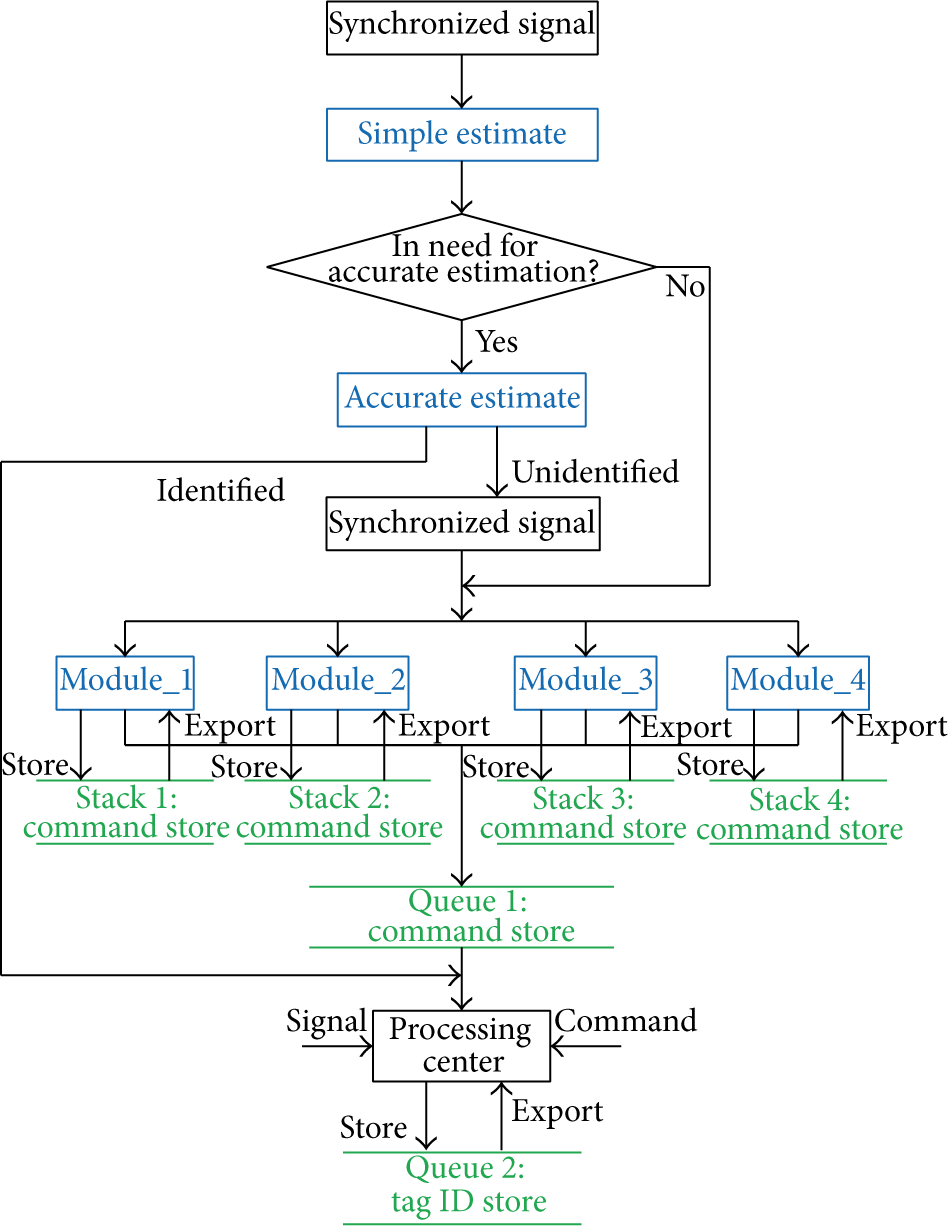
Flow chart of flood division anticollision (FDAC) algorithm.
3.2. Key Terms and Commands Explanation
(1) Division Modules. The modules are divided into several parts: module_1, module_2, module_3, module_4, and so forth, which are labeled, respectively, with module IDs. The thresholds (which can be changed) are set and used to start modules working according to the number of collision tags. For example, if the number of collision tags is in the range of 1–16, only module_1 starts working, when the number is in 17–64, two modules (module_1, module_2) start working, when the number is in 65–521, three modules (module_1, module_2, and module_3) start working, when the number is in 513–2048, four modules (module_1, module_2, module_3, and module_4) start working, and so forth.
(2) Module Labeling. Module labeling is an operation to assign IDs to the started working modules, and the IDs are sequences of 0 or 1. The module labeling operation does not need to be done if the RFID tags are less and need only one module to work. If two modules (i.e., module_1 and module_2) work, the two modules are labeled with 0 and 1, respectively. If three or four modules (i.e., module_1, module_2, module_3, or module_4) work, they are labeled with 00, 01, 10, or 11, and so on when more modules need to work.
(3) Tag Collision Criterion. Tag collision criterion is whether there are collisions between the parameters sent by tags. If only one collision bit is detected, two collision tags can be directly identified without the need for a command from reader. If collision does not happen, we can conclude that only one tag exits in the system which can be identified directly. When a collision tag needs to respond to the reader, only the parameters (0 or 1) of the collision bits (not all bits of the tag ID) are sent to the reader, which can decrease the data transmitted between the collision tag and the reader.
(4) Back Tracking Strategy. After a request command from reader is stored into a stack, it can be called out from the stack while it is in need again. This strategy is also called retrospective strategy.
(5) Parallel Processing. Parallel processing exists in two levels. Firstly, among the modules, all started modules work and process simultaneously. Secondly, in the module, the read-write operation and the collision processing are done simultaneously.
(6) Collision-Bit Tracking. When a reader sends a three-dimensional-vector command to the tags, each tag responds to the command with the collision-bit parameters of the tag ID. The collision bits are basic clue and are used in the process whether the reader sends a command or the tags respond to the command. So, tag collision identifying can be simply named collision-bit tracking.
(7) Request Command. When collision occurs, a request command is to be sent to the collision tags from the reader. For example, REQUEST(B, P, M) is a request command, “B” represents a collision bit, “P” is the collision parameter (0/1) of the collision bit, “M” is a mark of a module in which the REQUEST command exits, and “M” may be NULL when only module_1 works. When collision is detected, the reader will send a REQUEST command again to the collision tag in which the parameter “B” is assigned a value with the highest bit of the collision bits that the collision tag responded to the last REQUEST of the reader with. If no collision occurs, the back tracking strategy will be started by the reader. In the process of the request command, the collision tag does not every time need to send the completed ID to the reader (only in the first time of the REQUEST), and meanwhile invalid commands are avoided as far as possible. So, the data bits that need to be transmitted can be reduced to a great extent.
(8) Answer Command. The answer command is used to answer to the request command of the reader. For example, ANSWER(f) is an answer command in this algorithm and the parameter “f” is a sequence comprised of the other collision bits which is lower than “B.”
3.3. Setting of Tag State
One tag, while it is within the interrogation zone of the reader, always possesses one of the four states: Standby, Silence, Killed, and Ready.
Standby. After having done a response with
Silence. After the tag ID is identified, the tag turns into the Silence state and does not participate in the competition with other tags and waits for writing the operation.
Killed. After completing the writing operation, the tag turns into Killed state and exits from the set of tags.
Ready. After
3.4. Estimation of Tag Number
(1) Simple Estimation. The reader broadcasts synchronization signal to all tags, and after receiving the signal each tag sends its ID to the reader. If collision occurs, the reader detects the collision bits. Let the number of the collision bits be X. The number of tags is
(2) Accurate Estimation. In RFID system, L and n are assumed to be, respectively, the frame size and the number of tags. In practice, it is reasonable to assume that n is not known and has to be estimated based on the observed read results. For an observed read result
Lower bound algorithm was proposed by Harald Vogt, which is obtained through the observation that a collision involves at least two different tags. Therefore, a lower bound on the value of n can be obtained by the simple estimation function nLB
Schoute tag estimation mechanism is based on a prerequisite hypothesis that the system has the maximum throughput rate of tags in a frame. The number of tags is estimated by multiplying the number of collision slots
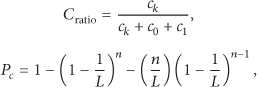
Collision ratio mechanism assumes that the slot collision ratio is equal to the expectation slot collision probability
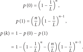
Vogt method is based on the fact that the outcome of a random experiment is most likely somewhere near the expected value. Thus, an estimation function uses the distance between the read result and the expected value vector to determine the value of n for which the distance becomes minimal [43]. In this paper, an improved Vogt method with Chebyshev inequality is used. We suppose the matter in which one tag appears in a time slot subject to a binomial distribution. The probability that r tags appear in a time slot can be computed as in the following equation:

Let
In a frame, the average values of empty time slots, successful time slots, and collision time slots can be represented as

Actually,


Figure 2 shows the mean estimation error of the four methods, which is defined as the mean difference between the real number and the estimated number of tags. The Vogt with Chebyshev method presents the most efficient estimation performance among the methods. So, in this paper, we use this method to estimate the tags in the accurate estimation.

Difference between the real number and the estimated number of tags.
3.5. Identification Algorithm
The process of the flood division anticollision (FDAC) algorithm has been presented in Figure 2. The detailed algorithm is described as shown in Algorithm 1.
(1) //α is the parameter to start accurate estimation; (2) (3) (4) Sort Tag Ids; //In ascending order; (5) Byte_Collision_bits ≔ Detect(Collision bits); //Detect get collision bits from collision signal; (6) Bit_Num ≔ Count(Byte_Collision_bits); (7) (8) { Assign all tags to Model 1; (9) Start (Model_1 (run()); //Model_1 operates the run() to identified tags; (10) Output (List of identified tag Ids); } (11) (12) { Tag_Num ≔ Accurate_Estimation(Tags); //Start accurate estimation; (13) (14) (15) { Assign all tags to Model_1; (16) Start (Model_1(run(NULL)); }; (17) (18) { Make tags into 2 groups; //Set groups in IDs order; (19) Assign Group 1 to Model_1; (20) Assign Group 2 to Model_2; (21) Do in parallel { Start (Model_1(run(1)); (22) Start (Model_2(run(2)); }; } (23) (24) { Make tags into 3 groups; //Set groups in IDs order; (25) Assign Group 1 to Model_1; (26) Assign Group 2 to Model_2; (27) Assign Group 3 to Model_3; (28) Do in parallel { Start (Model_1(run(1)); (29) Start (Model_2(run(2)); (30) Start (Model_3(run(3))}; } (31) (32) { Make tags into 4 groups; //Set groups in IDs order; (33) Assign Group 1 to Model_1; (34) Assign Group 2 to Model_2; (35) Assign Group 3 to Model_3; (36) Assign Group 4 to Model_4; (37) Do in parallel { Start (Model_1(run(1)); (38) Start (Model_2(run(2)); (39) Start (Model_3(run(3)); (40) Start (Model_4(run(4)); }; } (41) ⋯ (42) } (43) (44) Output (List of identified tag Ids); (45)
After being divided into groups, the RFID tags are assigned to the models. The operation that tags are identified in model_i is described as shown in Algorithm 2.
(1) (2) Byte_Collision_bits ≔ Get Byte from Collision Tag IDs; (3) High_bit.Index ≔ Get_Highest_bit_Index(Byte_Collision_bits); //Get the highest collision bit Index; (4) High_bit.value ≔ Get_Highest_bit_Value(Byte_Collision_bits): //Get the value of the highest collision bit; (5) (6) { (7) REQUEST(High_bit_Index, High_bit_value, i); //Reader send REQUEST to the tags; (8) ANSWER (f); //Tags respond with f; (9) (10) { Store REQUEST(High_bit_Index, High_bit_value, i) into the stack; (11) Collision Tags turn into Standby; (12) Store collision information; (13) Assign next high collision bit to the High_bit; } (14) (15) { Tags be identified and turn into the Silence; (16) If need write, wait for write operation; } (17) (18) Call REQUEST(High_bit_Index, High_bit_value, i); //Back tracking strategy; (19) High_bit_value ≔ ~(High_bit_value) (20) } (21) }
An example that tags are processed with Operation run(i) is as follows. We assume that 8 activated RFID tags are grouped and assigned to model_i, and the IDs of the tags are tag_i_1: 10110011, tag_i_2: 11011011, tag_i_3: 10010001, tag_i_4: 11111011, tag_i_5: 10011011, tag_i_6: 11110001, tag_i_7: 11010011, and tag_i_8: 10011001. The reader can detect a signal “1??1?0?1” in model_i, which expresses that collisions occur in four bits: Di1, Di3, Di5, and Di6. The process that the tags are identified with Module_i is as in Figure 3. Finally, all eight tags have been identified. Writing operation, if tags need, can be started after the tags turn into Silence state.
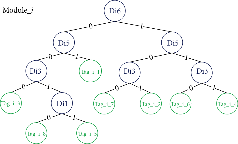
Process of 8 RFID tags identified in Module_i.
4. Simulation and Analysis
The simulation condition is as follows. There is only one reader, and in the field of the reader, the number of tags increases from 2 to 1000. Both tag-to-reader data rate and reader-to-tag data rate are chosen as 40 kbps. The reason is that the middle speed in EPC Class 1 Gen.2 proposed by EPC global to ISO/IEC 18000-6 B is equal to the chosen data rate [43]. There is some iteration overhead because of propagation delay from the channel and latency from the signal processing. Here, the iteration overhead is not considered for the simulation. The IDs are randomly generated.
We simulate FDAC and compare it with the dynamic frame slotted (DFS) Aloha algorithm, the binary-retreat tree (BRT) algorithm, and the dynamic binary-search tree (DBST) algorithm in terms of the number of data bits transmitted by reader, the number of data bits transmitted by tags, and the identification time delay [44, 45]. In the simple estimation of tag numbers, we set the threshold
4.1. Number of Data Bits Transmitted by Reader
DFS needs many communication rounds to optimize the frame size in the identification process and needs the reader to send much more data bits to tags. In DBST, the tag ID is divided into known part and unknown part, and in the search process only the known part needs to be transmitted between tags and reader, which reduce data transmission between the tags and the reader. In BRT, some data structure technologies are used to store and remember the previously used commands which will only be imported while it would be in need again. In FDAC, the back tracking strategy is used to process the REQUEST command which reduces the times of the REQUEST command sent by the reader. And while needing to send a REQUEST command, the reader only needs to send a three-dimensional-vector command, and the tags respond to the command with part of the collision-bit parameters.
Figure 4 shows the amount of data bits transmitted by the reader in varied number of the tags. Although the numbers of data bits transmitted by the reader of the four algorithms nearly increase linearly with varied number of tags, the FDAC has the best data transmitting performance among the four algorithms. The data transmitted by the reader in FDAC is only 26%, 42%, and 63% of that in DFS, DBST, and BRT, respectively, for 1000 tags.

Plot of the data transmitted by reader of the four algorithms.
4.2. Number of Data Bits Transmitted by Tag
As described previously, in DBST, the tag ID is divided into known part and unknown part, and in the search process only the known part needs to be transmitted between tags and reader, which also reduce data transmission from the tags to the reader. In BRT, the data structure technologies are used to store and remember the previously used commands, which reduce not only the data transmission from the reader to the tags but also the data transmission from the tags to the reader. In FDAC, while responding to the request command, the collision tag does not every time need to send the completed ID to the reader (only in the first time of the REQUEST).
Figure 5 shows the average data bits transmitted by each tag. FDAC has also the best data transmitting performance by tags among the four algorithms. The average data transmitted by each tag in FDAC is only 22%, 32%, and 38% of that in DFS, DBST, and BRT, respectively, for 1000 tags.

Plot of the data transmitted by tags of the four algorithms.
4.3. Tag Identification Time Delay
We compare FDAC with DFS, DBST, and BRT in terms of the tag identification time delay, which is the elapsed time for a reader to identify all tags in the interrogation zone. The tag identification time delay Td is defined to be [37, 38]

The notations used in (7) are shown as follows:
In FDAC, the mechanisms that reduce data transmission between the tags and the reader help to save the identification time. More importantly, the parallel processing technology among the modules with the flood division anticollision algorithm mainly contributes to better identification time performance, especially in the case of much more tags.
Figure 6 presents the comparison of the identification time delay between the four algorithms, and FDAC has the best performance of identification time. The identification time delay in FDAC is only 17%, 23%, and 29% of that in DFS, DBST, and BRT, respectively, for 1000 tags.
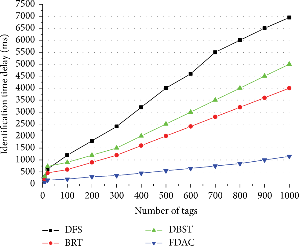
Plot of identification time delay of the four algorithms.
4.4. Energy Consumption of Reader and Tag
We compare FDAC with DFS, DBST, and BRT in terms of the energy consumption of the reader and tags, according to the energy consumption evaluation framework presented by Yan and Liu in [35]. In the evaluation framework, the energy consumed by the reader in a tag collision resolution cycle had been classified as the energy consumed in broadcasting command messages and that in listening to the tag responses, and the energy consumed by the tag had been classified as that consumed in transmitting its modulated signals and in listening to the command messages broadcasted by the reader.
Figure 7 presents the energy consumed by the reader with the four algorithms. The FDAC performs the best, and the DFS consumes much more energy than the other three algorithms. We think it is due to the fact that DFS needs much more communication rounds to optimize the frame size in the identification process and needs the reader to send much more data and that the FDAC reduces the REQUEST command sent by the reader.

Plot of energy consumption of the reader with the four algorithms.
Figure 8 presents the average energy consumed by a tag with the four algorithms. The FDAC needs less energy than BRT and DBST but needs more energy than DFS. The reason why the FDAC needs more energy than the DFS is that the FDAC needs more listening to the command messages broadcasted by the reader than the DFS.

Plot of average energy consumption of a tag with the four algorithms.
5. Conclusions and Future Research
In this paper, we investigated the tag identification problem in RFID system. Firstly, we surveyed the existing algorithms for anticollision of tags. Then, we proposed a new anticollision algorithm based on flood division idea to reduce data bits transmitted and identification time delay. And, we simulate the FDAC and compare it with the DFS, the BRT, and the DBST in terms of the number of data bits transmitted by reader, the number of data bits transmitted by tags, the identification time delay, and the energy consumption by the reader and tag.
The results of the simulation experiment show that FDAC has better performance than DFS, BRT, and DBST, whatever in data transmitted and identification time delay or in energy consumption by the reader. About the energy consumption by a tag, the FDAC shows better performance than DFS but less than the BRT and the DBST.
In the future works, we will improve the FDAC especially in the energy consumption.
Footnotes
Conflict of Interests
The authors declare that there is no conflict of interests regarding the publication of this paper.
Acknowledgments
This research was supported by the National Natural Science Foundation of China under Grant 6074308, the Key Scientific and Technological Projects of Henan Province in China under Grant 142102210045, and the project sponsored by SRF for ROCS, SEM. The authors would like to thank the reviewers for their valuable comments.