
Abstract
In Wireless Sensor Networks (WSNs), disaster management is a crucial issue that focuses on disaster relief and recovery. Mobile sensor nodes support disaster relief and recovery by means of real-time bidirectional communication. For its high data rate requirement, IEEE 802.11 specification can be used for the radio interface of sensor nodes, and the nodes can be equipped with multiple 802.11 radios to utilize multiple channels and link data rates. Channel assignment algorithms can be applied in cognitive radio enabled networks which performs dynamic channel configuration for utilizing multiple channels. For efficient and semireliable broadcast in cognitive radio WSNs, we focus on reducing broadcast latency and achieving 100% delivery percentage. To realize these goals, in this study, we present our design for a novel Channel Assignment Algorithm for a Collision-Reduced Broadcast Tree (CA-CBT). Fundamentally, CA-CBT builds a broadcast tree and then uses several heuristic procedures to allocate collision-free channels to links on the tree. If CA-CBT fails to allocate collision-free channels due to a limited number of available channels, it allocates non-collision-free channels with the smallest number of interfering nodes. Through extensive simulations, we demonstrated that CA-CBT supports lower broadcast latency and higher delivery percentages compared with existing broadcast algorithms.
1. Introduction
Disaster management has been widely studied in wireless sensor networks [1]. Conventional studies primarily focused on disaster detection and efficient reporting from sensing nodes to a sink node; however, recent studies have expanded to cover disaster relief and recovery. For example, mobile sensor nodes, such as those embedded on robots, may be deployed to dangerous environments, including areas afflicted by toxic gas leaks, radiation exposure, and earthquakes. These nodes download data from a sink node such as a gateway or command center and then communicate with nearby sensor nodes to support disaster relief and recovery by means of real-time bidirectional communication. In wireless sensor networks (WSNs), each mobile sensor node can be equipped with multiple radio interfaces to deliver large or small sensing data [2–4].
Designing channel assignment algorithms to exploit multiple channels is similar to the concept of cognitive radio in that multiple available channels are utilized. Hence, our research considers cognitive radio WSNs with multiple channels for transporting large data from a sink node to mobile sensor nodes.
In multichannel WSNs, nodes can utilize multiple channels available within 802.11 specifications via multiple interfaces to deliver traffic in parallel. When the number of nodes increases, nodes require more channels to enable more concurrent transmissions over different channels; however, 802.11 supports only a limited number of channels. For example, 802.11b/g and 802.11a support three and 12 nonoverlapping channels, respectively. Such limitations force nodes to share the common channel, which increases network interference and significantly degrades networks performance. To solve this problem, channel assignment algorithms have been extensively explored [5–11], all of which primarily focus on unicast transmissions.
In addition to multiple channels, off-the-shelf 802.11 devices also provide a multirate function. Depending on the channel condition, a node can transmit its data frame over a wireless link by using multiple data rates. In multirate networks, there is a tradeoff between the transmission range and the data rate (or latency) of links. For example, when the data rate of a link decreases, the transmission range of the link increases. In wireless networks, a packet that is broadcast by a sender can be received by all neighbor nodes within transmission range of the sender (assuming omnidirectional antennas), a phenomenon known as wireless broadcast advantage (WBA) [12]. WBA stems from the broadcast nature of the wireless channel; hence, broadcasting in multirate networks can exploit WBA by controlling the tradeoff between the transmission range and the data rate of links. Although this tradeoff is primarily utilized for unicast transmissions, we can also make use of the tradeoff for broadcast transmissions as [13–19].
To satisfy the requirements, both efficient and low latency broadcasting are critical. To address these requirements, several solutions have been proposed [13–19], all of which assume a proper channel assignment of links. As such, these studies focus on constructing a broadcast tree rather than assigning available channels to links on the broadcast tree.
Therefore, our key research objective was to design a channel assignment algorithm for efficient and semireliable broadcasting in WSNs. Our proposed algorithm assigns channels to links on the broadcast tree by fully utilizing all available channels supported by 802.11 devices. For efficient and semireliable broadcast, we use broadcast latency and delivery percentage as metrics, as defined in [13]. Broadcast latency is defined as the elapsed time between the broadcast source sending a packet and all nodes in the network receiving it. More specifically, the minimum latency broadcast problem has been proven to be NP-hard due to the complexity in multichannel multiradio multirate networks [20].
Delivery percentage is defined as the number of nodes that receive a packet (sent by the broadcast source) divided by the total number of nodes in the network. Improving the delivery percentage is also a challenging problem since the delivery percentage metric reflects the collision degree of broadcast packets on the channels. In particular, 802.11 does not use the retransmission scheme for broadcast packets when the broadcast packets experience collisions caused by the hidden terminal problem, whereas unicast packets take advantage of this retransmission scheme. When transmitting a stream of broadcast packets, the delivery percentage decreases more significantly. Hence, our interest here lies in designing a channel assignment algorithm that makes full use of available channels to reduce broadcast latency and achieve up to 100% delivery percentage.
Given the above, in this paper, we propose a centralized channel assignment algorithm for a Collision-Reduced Broadcast Tree (CA-CBT) in WSNs. CA-CBT builds a shortest path tree by using the path cost metric and Dijkstra's algorithm. Next, CA-CBT traverses each node for the channel assignment of a parent node and its child nodes. CA-CBT attempts to assign channels that guarantee collision-free broadcasting by using three heuristic procedures. When the number of available channels is small, the number of nodes assigned with non-collision-free channels increases on the tree and those nodes can be influenced by interfering nodes. Thus, if CA-CBT fails to guarantee collision-free broadcasting, it then tries to assign channels that do not guarantee collision-free broadcast but have the smallest number of interfering nodes. Further, to improve the delivery percentage, CA-CBT compensates those nodes that could experience collisions by allowing them to receive redundant broadcast packets from one more parent node. In contrast, when the number of available channels is not small, the possibility of assigning non-collision-free channels is small and thus the delivery percentage can be increased. Since CA-CBT fully utilizes all available channels with a limited number of NICs, it is beneficial when the number of channels is larger than the number of NICs per node.
Through extensive ns-2 simulations, we showed that CA-CBT was able to achieve lower broadcast latency and higher delivery percentages as compared with existing broadcast algorithms.
In addition to this introductory section, the remainder of this paper is structured as follows. In Section 2, we survey related work. In Section 3, we define our research objective and provide a system model and several terms used in CA-CBT. Next, we propose our detailed CA-CBT in Section 4. In Section 5, we evaluate the performance of CA-CBT and compare it with existing broadcast algorithms. Finally, we conclude our paper and suggest directions for future work in Section 6.
2. Related Work
Recently, several algorithms have been suggested for broadcasting in WSNs. These algorithms can be classified into centralized algorithms [13–16] and distributed algorithms [17, 18]. In centralized algorithms, we assume a centralized entity, such as a gateway node, collects global WSN information from all nodes. For instance, in [13], Qadir et al. developed a locally parallelized multiradio multichannel weighted connected dominating set (WCDS) tree (LMT) and a parallelized approximate-shortest multiradio, multichannel WCDS tree (PAMT). Both LMT and PAMT build broadcast trees by specifying four tuples consisting of the transmitting node, the receiving nodes, the latency, and the channel. In LMT, the algorithm attempts to decrease the number of contending transmissions on the common channel. In PAMT, the algorithm tries to increase parallelization (i.e., by activating more interfaces).
In [16], Li et al. jointly formulated the broadcast routing and channel assignment problem using a mixed-integer linear programming approach. They then proposed a heuristics-based broadcast algorithm. Conversely, distributed algorithms require nodes to exchange control messages with neighboring nodes to utilize local information regarding the WSN. For example, the multiradio distributed tree (MRDT) approach [17] uses RREQ and RREP messages to calculate a low latency broadcast tree by considering interface, channel, and rate diversities.
In the literature, several algorithms have been proposed that make use of breath-first search (BFS) for broadcasting in multihop wireless networks [20–22]. In the BFS-based broadcast algorithms, receiving nodes may experience packet collisions when a number of nodes are transmitting broadcast packets in a single-channel single-rate wireless network. To combat this problem, a time slot is defined in the algorithms as the time duration between the time when the source node transmits a broadcast packet and the time when the receiver nodes receive the broadcast packet. The algorithms then schedule time slots to minimize the number of such slots required for transmitting broadcast packets.
Our main interest lies in designing a channel assignment algorithm for broadcasting in WSNs. In most of the aforementioned algorithms, the focus has been on the construction of a broadcast tree rather than the channel assignment algorithm itself. That is, after assuming channels have been assigned to available interfaces, they construct the broadcast tree by using available links. Regarding channel assignments, in [13], Qadir et al. concluded that the common channel approach (CCA) is a good strategy for broadcasting among existing channel assignment schemes, which are designed for unicast flows, such as CCA [9], the varying channel approach (VCA) [10], and interference survivable topology control (INSTC) [11].
In CCA, the number of equipped interfaces per node is equal to the number of available channels, and each interface is assigned a distinct channel. Thus, each node has full connectivity to neighboring nodes within its transmission range. For VCA, nodes use one NIC on a common channel to ensure network connectivity, making use of the other remaining NICs on random channels. INSTC performs channel assignments to reduce network interference. According to [13], CCA works well for broadcasting since it is simple and adjacent nodes can utilize a common set of channels; however, when the number of NICs per node is smaller than the number of available channels, the channel diversity of CCA is restricted to the number of equipped NICs, which may lead to low broadcast performance in WSNs.
3. Research Objective, System Model, and Definitions
3.1. Research Objective and System Model
Our research objective was to design a channel assignment algorithm to support efficient and semireliable broadcasting in WSNs. We consider both efficient broadcasting by reducing broadcast latency and reliable broadcasting by achieving up to 100% delivery. To achieve our goals, we developed a channel assignment algorithm that assigns channels to links in WSNs and fully utilizes all channels with a small number of NICs for broadcasting in WSNs.
We assumed a multichannel multiradio multirate WSN in which nodes are equipped with multiple (at least two) IEEE 802.11 NICs. Although our proposed algorithm can be used in WSNs in which the number of available channels is larger than the number of NICs per node, we considered only IEEE 802.11a-based WSNs that support 12 noninterfering channels and data rates from 6 Mbps to 54 Mbps.
We also assumed the mutual interference model for our network interference model; that is, two transmitting nodes A and B interfere with one another if the following two conditions are met: (1) both nodes A and B transmit at the same time on the common channel and (2) the receiving nodes of node A's transmission are in the interference range of node B and vice versa.
3.2. Definitions
In this subsection, we define several terms used in CA-CBT. Fundamentally, CA-CBT constructs a spanning tree rooted at the gateway node that serves as the broadcast source of the tree. Nodes use available interfaces in three distinct ways, namely, a receiving NIC (RI), a transmitting NIC (TI), and a free NIC (FI). The RI is used to receive broadcast packets from one or two parent nodes. The TI is used to transmit the received packet to its child nodes. All remaining NICs except for RIs and TIs become FIs. Further, each node can use one or more TIs and RIs, with TIs and RIs on the same node able to be assigned to different channels. Depending on the channel assignment algorithm, a node can transmit broadcast packets to its child nodes in parallel by using multiple TIs and link data rates. The node can also receive broadcast packets from one or two parent nodes through multiple RIs.
Figure 1 shows an example that consists of a broadcast source (node S), a parent node (node A), and three child nodes (nodes B, C, and D) of node A. Depending on link data rates, links are depicted differently; that is, each link is labeled by the broadcast rate and channel number. For example, links A-B, A-C, and A-D can use 54 Mbps, 36 Mbps, and 12 Mbps, respectively. Each node is equipped with three NICs, and parent node A uses two TIs and one RI. One TI transmits broadcast packets on channel two using 54 Mbps, while the other TI transmits broadcast packets on channel three using 12 Mbps. Here child nodes C and D are associated with one TI on parent node A via link A-C (36 Mbps) and link A-D (12 Mbps), respectively. Fundamentally, the transmission range of low data rates is larger than that of high data rates. Therefore, parent node A uses the broadcast rate for broadcasting to its child nodes, which is the lowest data rate among the data rates of links A-C and A-D.

An example network setup depicting definitions used in CA-CBT.
For channel assignments, we define group
According to channel conditions, we define available channels as either collision-free channels (CF-channels) or non-collision-free channels (CN-channels). If there is no interfering node on a channel when the parent node transmits a broadcast packet to its child nodes in group G, the channel is a CF-channel for group G; otherwise, it is a CN-channel for group G. During channel assignments, the channel assignment algorithm maintains the following information for each group: a set of CF-channels (
4. Channel Assignment Algorithm for a Collision-Reduced Broadcast Tree (CA-CBT)
In this section, we describe the design of our centralized channel assignment algorithm, CA-CBT, in relation to WSNs. We start by describing the centralized operation to gather global network information from nodes in a WSN, which is required for the channel assignment algorithm of CA-CBT. After describing the tree construction algorithm, we then present the main portion of CA-CBT in detail.
4.1. Centralized Operation
Since CA-CBT uses a centralized algorithm, the gateway node gathers network information from nodes of a WSN; such information is required for the algorithm of CA-CBT. Initially, all nodes operate on the common channel by using one of their NICs. To obtain each neighbor node's information, nodes (say node X) exchange HELLO messages with their neighboring nodes (say node Y) within H-hop range. This neighbor's information of node X includes the data rate of link X-Y, the addresses of one-hop neighbor nodes around node X, and the address of interfering nodes within the interference range of node X. Here, H-hop is the ratio between the interference range and the transmission range. Since the H-hop value is small, nodes do not flood HELLO messages network-wide.
After obtaining a neighbor's information, nodes report such information to the gateway on the common channel by using a well-known routing protocol, such as AODV [23]. Once the network information is gathered, the gateway node performs the channel assignment algorithm of CA-CBT that determines the channel of links and routing paths on the broadcast tree. To notify all nodes of the algorithm's results, the gateway broadcasts Advertisement messages on the tree. Then, nodes that received the message are able to assign channels to their NICs and update routing tables accordingly.
4.2. Tree Construction
For broadcast in WSNs, Chou et al. [14] proved that transmitting broadcast packets at a higher data rate is better than at a lower data rate. Moreover, in [13], Qadir et al. insisted that a low data rate link increases broadcast latency over some links, that is, those links that can transmit faster without it. Therefore, we utilize high-rate links instead of low-rate links wherever possible during tree construction.
CA-CBT constructs a tree much like a shortest path tree by using a path cost metric. We adopted a similar approach as that of Dijkstra's algorithm in that each node maintains a measure from the broadcast source (i.e., the gateway node). Here, when link i uses data rate
Algorithm 1 shows the pseudocode of the tree construction algorithm in CA-CBT. We assume that network information is collected by using a centralized operation, as noted above in Section 4.1. Initially, the status of all nodes is set to “not updated” and the path cost value of all nodes is set to infinity (lines 1-2). Next, the algorithm traverses each node from the broadcast source node (i.e., the gateway node) via lines 5–14. Assume that broadcast source node S has two neighbor nodes X and Y as its candidate child nodes. For current node S, if node S provides the minimum
(0) (1) Set the status of all nodes to “not updated”; (2) Set the path cost value of all nodes to “MAX”; (3) curr_node = S; (4) Set the path cost value of curr_node to zero; (5) (6) (7) (8) Update the path cost value and the parent node of cnn; (9) Set the status of cnn to “updated”; (10) } (11) } (12) Set the status of cn to “finished”; (13) curr_node (cn) = get_min_node(“updated”); (14) } (15) }
4.3. Channel Assignment Algorithm
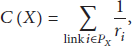
In this subsection, we propose the main algorithm of CA-CBT. Figure 2 illustrates the entire procedure of CA-CBT. After a tree is constructed (i.e., Section 4.2), CA-CBT performs channel assignments for links and determines routing paths on the tree by using the five procedures labeled from P1 to P5. The algorithm uses BFS to traverse nodes on the tree from the broadcast source node to the leaf nodes. The path cost (C) value of nodes determines the traversal order, and at each iteration, the node with a minimum C becomes the first node of the BFS.

The entire procedure of the CA-CBT algorithm.
For each traversal, the algorithm visits the current visited node (say node X), allocating one or more group channels to the group that includes current node X and its child nodes. Since the number of available channels is limited in IEEE 802.11, CF-channels may or may not be available. Depending on the availability of CF-channels, channel assignments fall into one of the following three cases.
Case 1.
When node X can use multiple TIs and there are enough CF-channels for each TI, node X can use multiple CF-channels via TIs for collision-free broadcasting. As a result, parent node X of group
For example, in Figure 1, parent node A has two TIs and three links, that is, A-B (54 Mbps), A-C (36 Mbps), and A-D (12 Mbps).
Case 2.
When node X can use multiple TIs but there is no CF-channel, CA-CBT obtains at least one CF-channel by using up to three iterations of Channel Reassignment (P1), Link Merge (P2), and Range Expansion (P3), each of which is discussed in this subsection. If CF-channels are obtained through these procedures, CA-CBT assigns the CF-channels to group
Case 3.
If CA-CBT cannot obtain CF-channels by using the aforementioned procedures, it assigns CN-channels to group
We describe the five aforementioned procedures below.
Procedure 1 (Channel Reassignment).
Suppose that CA-CBT visits the current node (e.g., node X) and there is no CF-channel for group
The pseudocode of Channel Reassignment is shown as Algorithm 2. We explain this procedure by using the example shown in Figure 3. In this figure, solid lines are the links on the tree and dotted lines are the links not on the tree. Five channels are available, the current visited node is node B, and the dotted circles around nodes B and C represent the interference ranges of nodes B and C, respectively. In Figure 3(a), suppose that node B has no CF-channel for its child node E. Then, Channel Reassignment temporarily changes the CF-channels of the interfering group
(0) (1) (2) Group (3) (4) Group (5) Add the CF-channels to (6) } (7) } (8) Return (9) }
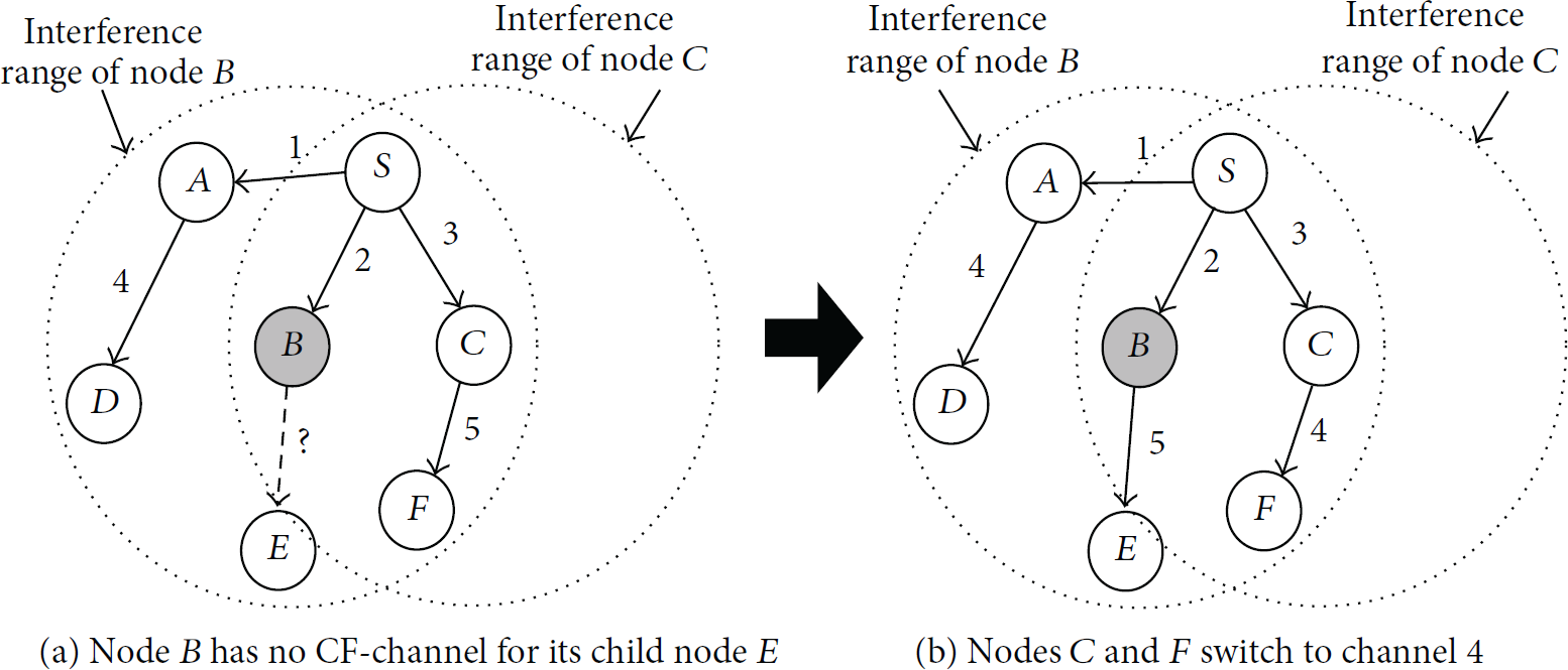
An example illustrating Channel Reassignment (Procedure 1).
Note that Channel Reassignment does not affect interference on group
Assuming that
Procedure 2 (Link Merge).
CA-CBT uses Link Merge when there is no CF-channel for current node X after Channel Reassignment (see Figure 2). The design goal of this procedure is to change the state of interfering groups from multi-TX to single-TX. In other words, CA-CBT requests only the interfering groups in a multi-TX state to decrease their number of assigned group channels in the groups. As a result of Link Merge, some groups in the multi-TX state may change to a single-TX state, and thus the current node X can obtain CF-channels.
Algorithm 3 shows pseudocode for Link Merge, while Figure 4 shows an illustrative example of this procedure in which all nodes on the broadcast tree are depicted by solid links. Dotted links are the links not on the tree. Each link is labeled with the corresponding broadcast rate and channel number. Suppose that the current node is node B and comprises five channels, and the dotted circle is the interference range of node B. In Figure 4(a), node B cannot use any CF-channels for link B-E after Channel Reassignment (P1).
(0) (1) (2) Select two TIs with the minimum broadcast rate; (3) Calculate (4) Perform Link Merge by selecting one of the TIs temporarily; (5) (6) Set the status of the interfering group (7) } (8) } (9) Get the interfering group with minimum (10) Perform Link Merge for the interfering group permanently; (11) Set the state of the interfering group to single-TX; (12) Add the obtained CF-channels to (13) Return (14) }

An example illustrating Link Merge (Procedure 2).
For Link Merge, CA-CBT requests the parent nodes of all interfering groups in a multi-TX state around node B to decrease the number of their group channels. First, the parent node of all interfering groups selects two TIs a and b with the two lowest broadcast rates (line 2). As shown in Figure 4(a), node S uses three TIs assigned to broadcast rates 54, 36, and 18 Mbps, respectively. It temporarily selects two TIs assigned to the two lowest broadcast rates of 36 and 18 Mbps. Second, CA-CBT calculates the delayed cost (
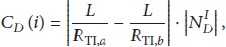
In (2), the delayed cost metric indicates the increased broadcast latency that can be experienced by the descendant nodes of the parent node of group
After calculating the delayed cost (
Once all interfering groups in the multi-TX state perform Link Merge temporarily, CA-CBT then selects the interfering group with the minimum
Link Merge iterates over the interfering groups of the current node for M TIs and K channels. When the average number of interfering nodes is
Procedure 3 (Range Expansion).
CA-CBT performs Range Expansion when current node X has no CF-channels after the Channel Reassignment and Link Merge procedures (see Figure 2). The design goal of the Range Expansion procedure is to decrease the broadcast rate of TIs on the parent node of current node X so that the parent node expands its transmission range to cover more child nodes of node X on the tree. In this procedure, the parent node of current node X assigns existing CF-channels to the child nodes of node X, where the covered child nodes should not be interfered with by other nodes on the assigned CF-channels.
We explain Range Expansion by using the pseudocode of Algorithm 4 and the example shown in Figure 5. In the figure, nodes S, A, and B are on the tree depicted by solid lines, while dotted lines represent links not on the tree. Each link is labeled by the broadcast rate and channel number. Further, the dotted circle represents the interference range of node B.
(0) (1) Select a set of TIs on the parent of node B, which ensures collision-free; (2) Select a TI with the minimum broadcast rate among the selected TIs; (3) Get the min data rate of links between node B and its child nodes; (4) Set the min data rate to the broadcast rate of the selected TI temporarily; (5) (6) Set the min data rate to the broadcast rate of the TI permanently; (7) } (8) }

An example illustrating Range Expansion (Procedure 3).
In Figure 5(a), suppose that the current node is node B and that it has no CF-channels for links B-C and B-D after the Channel Reassignment (P1) and Link Merge (P2) procedures have been completed. In Range Expansion, current node B makes its parent node (e.g., node S) decrease the broadcast rate of TIs on parent node S. If parent node S uses multiple TIs, it selects the TI with the lowest broadcast rate among TIs that guarantee collision-free transmission for the child nodes of node B (lines 1-2). Then, parent node S covers all child nodes of current node B by decreasing the broadcast rate of the selected TI (lines 3–7).
For instance, in Figure 5(a), parent node S of current node B selects the TI assigned to channel two at 48 Mbps, since the broadcast rate of the TI is lower than that of the other TI assigned to channel one at 54 Mbps (line 3). Next, node S decreases the selected TI's broadcast rate to cover all child nodes of node B (e.g., nodes C and D) as follows (lines 4–7). For simplicity, assume that the data rates of links S-C and S-D are 18 Mbps and 12 Mbps, respectively, and channels one and two are CF-channels. Then, the broadcast rate of the selected TI on parent node S is temporarily set to the lowest data rate, that is, 12 Mbps, as shown in Figure 5(b) (line 4). If parent node S can cover all child nodes of node B, it then sets the broadcast rate of the TI to the lowest data rate permanently (lines 5–7). In this way, CA-CBT can assign CF-channel two to child nodes C and D of current node B. If parent node S of node B cannot cover all child nodes of node B, CA-CBT proceeds to the fourth procedure, Forced Assignment, which does not guarantee collision-free broadcasting.
Range Expansion is only performed by the parent node of current node X for M TIs, K channels, and
Procedure 4 (Forced Assignment).
CA-CBT executes Forced Assignment when current node X cannot assign CF-channels for its child nodes after Channel Reassignment, Link Merge, and Range Expansion (see Figure 2). In Forced Assignment, CA-CBT assigns CN-channels with the smallest number of interfering nodes to the current group that comprises current node X and its child nodes. For CN-channel k, we define the total number of nodes in all interfering groups around current node X as
Since Forced Assignment calculates the
Procedure 5 (Redundant Reception).
CA-CBT performs Redundant Reception after all nodes of the tree are assigned CF-channels or CN-channels (see Figure 2). The design goal of Redundant Reception is to increase the possibility of broadcast receptions on CN-channels. Without Redundant Reception, CA-CBT ensures that each node receives broadcast packets from only one (primary) parent node; however, with Redundant Reception, the current node (say, node X) assigned CN-channels joins an additional (secondary) parent node if it has at least one RI for the secondary parent. This causes these nodes on CN-channels to receive, with high probability, broadcast packets from both the primary and secondary parent nodes. To join with this additional parent node, current node X selects the secondary parent node that provides smallest path cost
Figure 6 shows an example of Forced Assignment and Redundant Reception in which all nodes are on the tree. Here, each link is labeled by the channel number. Suppose that the current node is node E and the dotted circle is the interference range of node E. In Figure 6(a), node E receives broadcast packets from its primary parent node B on CN-channel two. To select a secondary parent node, node E considers neighbor nodes A, C, D, F, and H on the tree, as shown in Figure 6(b), excepting primary parent node B.

To select a secondary parent, the algorithm calculates path cost
4.4. Discussion
In summary, CA-CBT traverses each node of the tree by checking whether current node X has CF-channels or not. If there is no CF-channel for group
We summarize the features of the above five procedures as follows. First, Channel Reassignment does not degrade the broadcast performance of CA-CBT since it does not affect any broadcast rates of interfering groups around current node X. Second, Link Merge may degrade broadcast performance of all influenced descendant nodes of current node X, because it decreases the broadcast rate of interfering groups around node X; that is, it changes the state of those interfering groups from multi-TX to single-TX. Third, Range Expansion also degrades the broadcast performance of CA-CBT since the parent node of current node X decreases the broadcast rate of its TI to cover all child nodes of node X.
In short, Link Merge and Range Expansion may degrade the broadcast performance of CA-CBT; however, CA-CBT can guarantee collision-free broadcasting in a WSN through Channel Reassignment, Link Merge, and Range Expansion. Fourth, Forced Assignment cannot guarantee collision-free broadcasting, since it assigns CN-channels that include at least one interfering group; however, CA-CBT reduces interference by assigning CN-channels with the smallest number of interfering groups around current node X. Moreover, Redundant Reception compensates for the nodes assigned to CN-channels by allowing them to receive redundant broadcast packets from both primary and secondary parent nodes, thus increasing the possibility of broadcast receptions on CN-channels.
Complexity of CA-CBT. The tree construction process of Algorithm 1 visits N nodes by iterating over their one-hop neighbor nodes. This requires
Range Expansion (Algorithm 4) is only performed by the parent node of node X for M TIs, K channels, and
Based on our system model, we assume that the number of NICs per node (M) is smaller than that of available channels (K) in a WSN. Since CA-CBT uses these five procedures for each set of N nodes, we conclude that the overall complexity of CA-CBT is
5. Performance Evaluation
In this section, we evaluate the broadcast performance of CA-CBT by using ns-2 simulations [24]. For performance comparison, we considered three recently proposed algorithms for broadcasting in WSNs, that is, LMT [13], PAMT [13], and MRDT [17]. These three existing algorithms assign channels via CCA, which is known to be good for broadcasting in WMNs [13, 17]. For each simulation result, we generated 10 different scenarios, each scenario including a single broadcast source node (i.e., the gateway node) and from 40 to 100.
Broadcast destination nodes were randomly positioned in a network field of 1000 m by 1000 m [13–18]. For the physical and MAC layers, we used default parameters for IEEE 802.11a NICs, and each node was equipped with three IEEE 802.11a NICs. Based on IEEE 802.11a, nodes could use eight link data rates from 6 Mbps to 54 Mbps and 12 nonoverlapping channels. Further, radio propagation was modeled using the two-ray ground propagation model, and we configured distance ranges for different link data rates based on the Cisco Aironet IEEE 802.11a card data sheet [25].
We set the interference range to the transmission range of the basic data rate (i.e., 6 Mbps). For broadcast traffic, we used a single broadcast packet and a stream of broadcast packets. The payload size of a broadcast packet was set to 1000 bytes. For a stream of broadcast packets, the interpacket delay between two successive packets was set to 20 ms. Table 1 summarizes all of the simulation parameters for our evaluation study.
Simulation parameters for performance evaluation.

For a single broadcast packet, we used the following performance metrics: (i) broadcast latency, the elapsed time between the time when the broadcast source node transmits a broadcast packet and the time when the broadcast packet is successfully received by all nodes, and (ii) delivery percentage, the number of nodes that received a broadcast packet divided by the total number of nodes. For a stream of broadcast packets, we used the additional set of metrics from [13]: (iii) total broadcast latency, the elapsed time between the transmission time of the first broadcast packet and the reception time of the last broadcast packet at all nodes, and (iv) broadcast delivery percentage, the number of broadcast packets successfully received at all nodes divided by the number of packets to be sent at all nodes. We averaged each performance metric value over 10 different scenarios for each simulation result.
5.1. Performance with a Single Broadcast Packet
In this subsection, we evaluate the performance of CA-CBT with a single broadcast packet. Figure 7(a) shows broadcast latency with the number of nodes varied in a WSN, with results being averaged from 10 different scenarios. In each scenario, the broadcast source node (i.e., the gateway) transmitted one broadcast packet on the tree. Each node was equipped with three NICs and used 12 noninterfering channels. From the figure, when the number of available channels is not small, we observe that CA-CBT showed lower broadcast latency as compared to LMT, PAMT, and MRDT. For instance, when there were 80 nodes in the WSN, the broadcast latency of CA-CBT was approximately 30.26%, 35.19%, and 33.11% lower than LMT, PAMT, and MRDT, respectively.

Broadcast latency performance with a single broadcast packet for (a) three NICs, 12 channels and (b) three NICs, 100 nodes.
Figure 7(b) shows broadcast latency with a varying number of channels, with each result averaged over 10 distinct scenarios. In each scenario, the gateway node transmitted one broadcast packet. Further, the number of nodes was 100, and each node was equipped with three NICs. From Figure 7(b), when the number of channels was less than six, we observe that CA-CBT showed higher broadcast latency than LMT, PAMT, and MRDT. This occurred because CA-CBT may decrease the broadcast rate of the groups on the tree by using Link Merge and Range Expansion when a small number of channels are available; however, when there are more than six channels, we observe that CA-CBT showed lower broadcast latency than the other algorithms.
Based on the results of Figure 7, we make a number of observations. To reduce broadcast latency, the number of concurrent broadcasts, which is determined by the channel diversity of a broadcast tree, should be increased. In LMT, PAMT, and MRDT, channel diversity is restricted to the number of NICs per node since CCA only utilizes three channels through three NICs. We observe this phenomenon in Figure 7(b), where LMT, PAMT, and MRDT showed the same broadcast latency regardless of the number of available channels. Conversely, CA-CBT exploited all 12 of the nonoverlapping channels by using only three NICs, which definitely increased the number of concurrent broadcast transmissions on the tree, thus increasing the channel diversity of CA-CBT's broadcast tree.
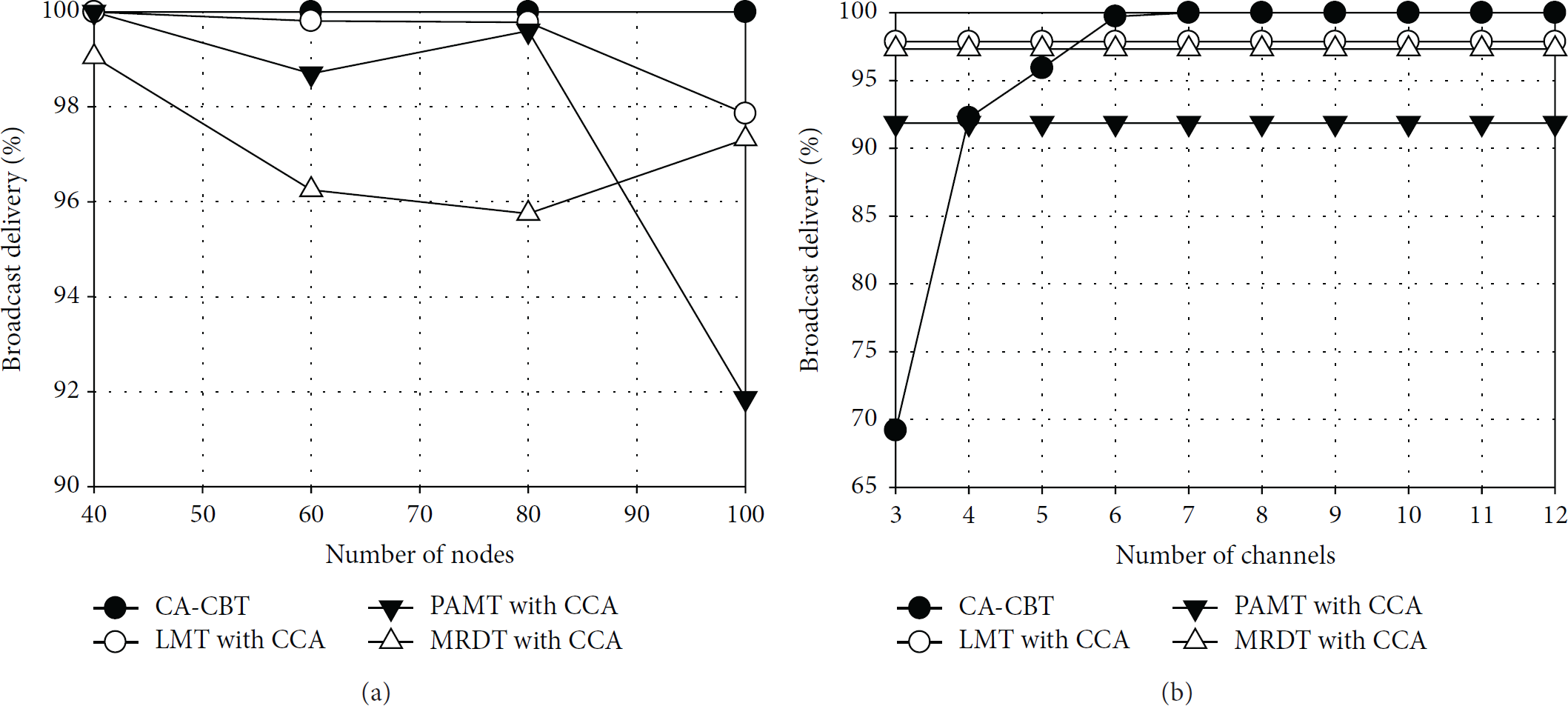
Figure 8(a) shows delivery percentage as the number of nodes increases. Results here are averaged over 10 different scenarios. In each scenario, a gateway node transmitted one broadcast packet. Each node used three NICs and 12 noninterfering channels. From the figure, we observe that CA-CBT showed 100% delivery percentage, whereas LMT, PAMT, and MRDT experienced packet loss due to broadcast packet collisions.

Delivery percentage performance with a single broadcast packet for (a) 3 NICs, 12 channels and (b) 3 NICs, 100 nodes.
Figure 8(b) shows the delivery percentage as the number of available channels was increased from three to 12. As per usual, we averaged results over 10 distinct scenarios. Each scenario included 100 nodes and a single broadcast source node that transmitted one broadcast packet. Each of the 100 nodes was equipped with three NICs. As observed in the figure, when the number of channels was small (e.g., less than five), CA-CBT showed lower delivery percentage as compared to LMT and MRDT. The reason here is that CA-CBT may use Forced Assignment for some groups on the tree, which cannot guarantee collision-free broadcasting; however, when the number of channels exceeded four channels, CA-CBT showed a higher delivery percentage than the other algorithms. In particular, when there were more than nine channels, CA-CBT achieved 100% delivery percentage with no packet collisions.
From the results of Figure 8, we explain the improved delivery percentage performance of CA-CBT as follows. In general, as the number of nodes increased, the number of interfering nodes increased on the common channels. Clearly, this also increased the probability of broadcast packet loss, primarily caused by collisions. To reduce packet collisions, LMT, PAMT, and MRDT attempt to cover many nodes with one broadcast transmission positioned in the transmission range of a transmitting node; however, as observed in Figure 8, they still suffer from collisions among broadcast packets since CCA utilizes only three channels via three NICs. On the contrary, CA-CBT fully utilized all available channels to avoid collisions through CF-channels. More specifically, this was achieved by using the Channel Reassignment, Link Merge, and Range Expansion procedures, which decreased the possibility of utilizing CN-channels that may introduce collision-based packet loss.
5.2. Performance with a Stream of Broadcast Packets
Next, we evaluated the performance of CA-CBT by using a stream of broadcast packets. Figure 9 shows the total broadcast latency for a stream of 100 broadcast packets, averaged over 10 different scenarios. The interpacket delay of the broadcast stream was 20 ms. In Figure 9(a), each scenario included a single gateway node and from 40 to 100 nodes. Each node was equipped with three NICs and used 12 noninterfering channels. In Figure 9(b), each scenario consisted of a single broadcast source node and 100 nodes, with each node using three NICs.

Total broadcast latency performance with a stream of 100 broadcast packets. (a) 3 NICs, 12 channels. (b) 3 NICs, 100 nodes.
From Figure 9(a), we observe that CA-CBT showed a lower total broadcast latency than that of LMT, PAMT, and MRDT, even with a stream of broadcast packets. For example, when there were 80 nodes in the WSN, the total broadcast latency values of CA-CBT, LMT, PAMT, and MRDT were 2011.0 ms, 2020.4 ms, 2023.2 ms, and 2047.9 ms, respectively. In Figure 9(b), when a small number of channels were available (e.g., less than four channels), CA-CBT showed a higher total broadcast latency than that of LMT, PAMT, and MRDT; however, CA-CBT supported lower total broadcast latency than the other algorithms when more than six channels were available.
Figure 10 shows the broadcast delivery percentage for a stream of 100 broadcast packets. Each result here was averaged over 10 different scenarios. We set the interpacket delay to 20 ms. Further, in Figure 10(a), each scenario consisted of a single broadcast source node and a varying number of nodes. The number of NICs per node was three, and there were 12 noninterfering channels. In Figure 10(b), each scenario made up a single gateway node and 100 nodes equipped with three NICs.
Broadcast delivery percentage performance with a stream of 100 broadcast packets for (a) three NICs, 12 channels and (b) three NICs, 100 nodes.
From Figure 10(a), we note that CA-CBT achieved 100% broadcast delivery percentage, whereas LMT, PAMT, and MRDT experienced some packet loss due to collisions. In the figure, CA-CBT showed a lower broadcast delivery percentage than that of the other algorithms when the number of channels was small (e.g., three channels); however, as the number of channels increased, CA-CBT achieved almost 100% broadcast delivery by fully utilizing every available channel in the WSN.
5.3. The Number of Required Channels for Collision-Free Broadcast
When the number of available channels is unlimited, CA-CBT can guarantee collision-free broadcast by assigning CF-channels to all groups on the broadcast tree; however, IEEE 802.11 standards specify a limited number of channels. Thus, we studied the number of channels required for guaranteeing collision-free broadcasting by CA-CBT as the number of nodes increases in a WSN. Specifically, this result indicates the number of required channels for which we would not perform the Forced Assignment and Redundant Reception procedures of CA-CBT. Figure 11 shows results averaged over 10 different scenarios with a 95% confidence interval. Each scenario included a single broadcast source node and from 50 to 100 broadcast receiver nodes randomly positioned in the network field. Each node used three IEEE 802.11a NICs and 12 noninterfering channels.

The number of required channels to guarantee collision-free broadcasting via CA-CBT (with three NICs per node).
In general, the number of interfering groups (or nodes) on the same channels increased as the number of nodes increased. Hence, as expected, we observe in Figure 11 that the number of required channels increased as more nodes were deployed; however, even when there were 100 nodes in the WSN covering a 1000 m by 1000 m field, which can be considered dense mesh router density in WSNs [26], the number of required channels was less than 12 on average. Therefore, if we assume IEEE 802.11a, which supports 12 noninterfering channels, CA-CBT can assign CF-channels to all groups on the tree without performing Forced Assignment and Redundant Reception to assign CN-channels.
5.4. The Number of Groups in the Multi-TX State
As the number of available channels increases, more groups can send broadcast packets in parallel by using multiple TIs. To observe this, we measured the number of groups in the multi-TX state by varying the number of channels. Figure 12 shows results with a 95% confidence interval that were averaged over 10 distinct scenarios. Each scenario consisted of a broadcast source and 50 nodes. The number of NICs per node was three.

The number of groups in the multi-TX state (50 nodes, three NICs).
From the figure, we observe that the number of multi-TX groups increased as the number of channels increased; that is, because CA-CBT can utilize more CF-channels and does not perform Link Merge by using additional channels, CA-CBT fully utilized additional channels for more multi-TX groups such that it reduced broadcast latency and improved delivery percentage.
5.5. Channel Diversity of CA-CBT and CCA
We investigated the channel diversity of CA-CBT and CCA used by LMT, PAMT, and MRDT. Here, we defined a metric called channel used ratio as the total number of channels utilized by each algorithm divided by the total number of channels available in the given scenario. As an algorithm utilized more channels, the channel used ratio increased. Figure 13 shows the channel used ratio of CA-CBT and CCA, averaged over 10 different scenarios. In each scenario, there was a single broadcast source node and from 50 to 100 nodes, each node consisting of three NICs and 12 noninterfering channels.

Channel use ratio as the number of nodes increases for three NICs, 12 channels.
As observed in Figure 13, CCA showed the same channel used ratio value irrespective of the number of nodes. The reason here is that CCA utilized only three channels through three NICs; that is, the channel diversity of CCA was proportional to the number of NICs per node. Conversely, the channel used ratio of CA-CBT increased as the number of nodes increased in the WSN, because CA-CBT utilized all available channels with only three NICs, indicating that the channel diversity of CA-CBT is not restricted to the number of equipped NICs.
6. Conclusion
In this paper, we presented our work on designing a centralized channel assignment algorithm, that is, CA-CBT, for efficient and semireliable broadcasting in WSNs. For efficient and semireliable broadcasting, we focused our efforts on reducing broadcast latency and achieving up to 100% delivery percentage. To realize these goals, our proposed CA-CBT algorithm fully exploited all available channels by using a small number of NICs. First, CA-CBT assigns CF-channels to links on the tree to support collision-free broadcasting. When CA-CBT cannot assign CF-channels, it assigns CN-channels by considering the number of interfering groups (or nodes). Next, the nodes assigned to CN-channels are compensated for by joining both primary and secondary parent nodes to redundantly receive broadcast packets.
We performed extensive ns-2 simulations with a single broadcast packet and a stream of broadcast packets. From our evaluation results, CA-CBT showed lower broadcast latency and higher delivery percentage as compared with existing broadcast algorithms developed for multichannel multiradio multirate WSNs. For our future work, we plan to extend our current CA-CBT algorithm to operate in a distributed way for more practical broadcasting in WSNs.
Footnotes
Conflict of Interests
The authors declare that there is no conflict of interests regarding the publication of this paper.