
Abstract
The most significant shortcoming of implanted devices is the battery life. With advanced technology, implanted devices can have the capability to communicate with other health-related devices, but this also means the energy consumption requirement is greater than ever. Less power consumption would extend the duration of the batteries of implanted medical devices. In this paper, an energy efficient and reliable communication service device scheme that does not require any modification to the existing wireless network structure or the implanted devices under consideration is proposed. The scheme is intended to save a target device's energy necessary for resending communication signals by introducing a neighbor group header node and cooperative (wearable) nodes. The simulation results show that the scheme would result in energy savings of 70 percent with one or two cooperative nodes as compared with the current best approach.
1. Introduction
The implant medical devices such as pacemaker, implantable cardiac defibrillator (ICD), neurostimulator system for deep brain stimulator, and insulin pump [1–4] are normally used to assist patient to maintain normal vital operation. Medical professions may need to monitor the implanted medical devices work as expected on patients; so the implanted devices would constantly transmit physiological signal back to medical data center for diagnosis. Many studies have proposed various solutions for inpatient monitoring and telemedicine [5–9]. The life of wireless implantable medical devices (IMDs) are usually limited by battery life. Additionally, besides supporting vital operation, the rest of the function provided by the implanted device is to handle the transmission of physiological signals. If the physiological signals received by the medial data center were incorrect or invalid, that would lead to incorrect diagnosis. Typically, IMD communicates with a receiver, which is a gateway to a remote server. Medical implant communication service (MICS) is a communication standard for medical and health care devices [10, 11]. An IMD adopts a MICS to communicate with a receiver, and the receiver will use a wired network to connect a server. The server stores long-term remote monitoring physiological IMD data. Medical staff give timely drug administration and treatments to an IMD wearer based on the wearer's stored data in the server. In addition, a medical professional can perform optimal adjustments to the operational parameters and dosages through wireless communication with an implanted device and can reduce the potential risks related to unexpected situations.
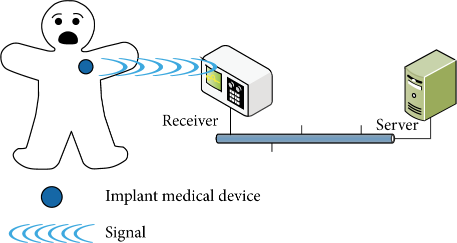
A typical installation that includes a wearer, a pacemaker, a receiver, and a server is shown in Figure 1. Currently most IMDs use an 802.15.6 [12] wireless body area network (WBAN) [13, 14] communication protocol. The 802.15.6 protocol follows the regulations on band definitions and channel requirements of MICS, and the transmission range is around 2 to 3 meters. A comparison between WLAN, WPAN (wireless personal area network), LR-WPAN (Low-Rate wireless personal area network), and WBAN is provided in Table 1.
Schematic overview of wireless technology in the medical application field.

Case of pacemaker.
As an IMD is implanted in human body, wireless signal attenuation problems can occur [17, 18]. In order to solve the wireless signal attenuation problem, a number of solutions have been proposed in research on this topic [19–21]. A comparison between different schemes [15, 16, 22] is shown in Table 2.
Difference schemes for physiological monitoring.

In this research, a new scheme, called
In addition, this proposed scheme adopts the IEEE 802.15.6 and 802.11, which are already equipped with special secure communication capabilities; therefore, the proposed paper only focuses on communication reliability and energy consumption and does not include security issues.
2.
MedRadio Scheme and Mechanism

A
A patient will have one or two wearable devices, which may be in the form of a wrist-ring, a patch, or others. The reliability of communication can be enhanced by group communication, which is built into the mobile nursing cart and the nearby wearable (cooperative) nodes because they have more powerful energy and communication capabilities. The nearby wearable (cooperative) nodes are used to relay the communication signals for the header node and IMDs. The advantage of our proposed scheme is that the implanted device can have longer battery life due to the fact that fewer retransmissions are required. On the other hand, the power consumption of the wearable device is increased because the tables maintained by the wearable devices (W nodes) can be frequently updated. However, this is an acceptable tradeoff because the wearable devices are much easier to recharge as compared with IMDs.
2.1. Assumptions
In order to make the proposed scheme work correctly, the following assumptions are required.
The IMD transmission range is limited to between 2 and 3 meters. Both wired and wireless communication infrastructure are required.
2.2. Cooperative Wireless Network Model
The nodes are divided into the following classes.
I (IMD) node: an implantable medical device. This type of node is for implantation purposes (e.g., stabilizing the heartbeat), and its communication ability is limited to receiving and responding to commands from the receiver. W (wearable or cooperative) node: a wearable device. This type of node is designed to receive/forward messages from/to the I node. It maintains a communication state list of where to send the received message. H (group header) node: A W node elected by other W nodes in a group. Generally it is a node having higher computing and transmission capability. Phase 0 (Algorithm 1) is the initialization phase. In this phase, all W nodes collect information of all neighbors and elect a header node. Phase 1 (Algorithm 2) is the join phase. In this phase, when a W node enters the communication zone, it receives invitations from groups and joins the existing group. Phase 2 (Algorithm 3) is the relay section phase. In this phase, the W nodes forward the message to their H node.
Figure 3 depicts a simplified
(1) Node collects information from neighbors and build a group table (GT); (2) Powerful node ID node number decrease 100; (3) GT = {node 1, node 2, …, node (4) (5) /*serve as the group header*/ (6) set group table flag = true; (7) set H_flag = true; (8) set GID = node ID; (9) invite (table's neighbor ID, self-node ID, GID); (10) (11) (12) /*serve as a cooperative node*/ (13) clear group table; (14) clear GID; (15) clear H_flag; (16) receive invitation and group table form H; (17)
(1) Node receives information from neighbors H and record to itself GT; (2) (3) receive invitation (H_ID, GID); (4) (5) Add H_ID to GT; (6) (7) (8) (9) chose minimum H_ID from GT; (10) send join message and self-node ID; (11) (12) Send leave node ID, Last_GID; (13) (14) set GID = H_ID; (15) set Last_GID = H_ID; (16) (17) Restart Initial Phase;
(1) Receive (W_ID, W_RELI_F, WIMD); (2) (3) (4) update GT; (5) update current allow W(W_ID, W_RELI_F, WIMD); (6) forward physiological signal; (7) chose maximum W_RELI_F from GT; (8) change H; (9) (10) (11) drop message; (12) (13) (14) (15) update GT; (16) update current allow W(W_ID, W_RELI_F, WIMD); (17)

Reliable and diverse transmission route path.
A more complicated scenario is shown in Figure 4. It is possible that

An example of
2.3. Algorithm Description
The proposed scheme includes three algorithms for which flow chart in Figure 5 and a detailed description is provided as follows.

Flow chart of our algorithm.
In phase 0, each node first builds a group table (GT) for itself and then collects neighboring nodes’ information to record the information into GT. After GT is established in each node, then all nodes participate in electing the H node. In this phase, in order to quickly form groups and have a header node to manage the group, GT only contains the ID for W nodes, and GT is sorted by the node ID in ascending order.
The node with smallest ID elected the H node and the node ID is group ID (GID). After the H node election, the elected H node broadcasts GT with its node ID listed on the top to all W nodes within the group in order to synchronize the GT.
After phase 0, which means groups are formed, and the H node is selected in each group, within each group, each W node sends a reliability factor to H node, and H node records all reliability factors from all W nodes into GT. The H node synchronizes GT that contains the W nodes’ ID and reliability factors to all W nodes in the group. Now, the W node with the highest reliability factor becomes the H node and resorts the GT according to the reliability factor in descending order. Then, the H node broadcasts the GT to all W nodes in the group. Selecting the node with highest reliability factor ensures the communication reliability.
In addition, each W node in the group maintains its own WIMD table, which records reachable IMD IDs and IMD reliability factors. All WIMD tables from all W nodes are sent to the H node in the group. When WIMD table is updated, the W node sends it to the H node for synchronization. In summary, within a group, each W node owns a WIMD table and is responsible for maintaining the WIMD table. Each H node owns n (the number of W nodes) WIMD tables and one GT. The H node is responsible for maintaining the GT.
In phase 1, because there is a group, if a node moves into the communication range of the H node, the node waits for an invitation for a time-to-live (TTL) period. If there are multiple invitations, then it selects the invitation from the one with the minimum header ID (H_ID) to join the group. On the other hand, if the node does not receive any invitations, the initial phase will restart again until the node either joins an existing group or becomes a one-node group by itself. Because the group forms an ad hoc network, all W nodes, are either in the initial phase or the join phase.
When an H node leaves or fails, other group members will remove the H node information from the GT, and the second node on the GT will be designated as the new H node of the group. In the worst case, if this newly selected H node still fails, then this group enters the initialization phase to select the H node instead of designating the third node on the GT to be the H node.
In phase 2 (relay selection phase), algorithm phase two is invoked. Two or three W nodes for relaying messages are chosen for the I node. The H node collects information including the ID of the W node (
If the W node's WIMD table is not “NULL,” then the H node checks the reliability factors to see whether the W node's reliability factor can be listed on the top three in the GT. If yes, then the H node updates the W node reliability factor in the GT and resorts the GT based on the value of the reliability factor. The three W nodes listed on the top three in the GT are the nodes selected to relay messages of physiological signal. If no, the W nodes’ messages will be dropped and also the H node updates the W node reliability factor in the GT even W nodes reliability factor without top 3. In addition, if the reliability factor of the W node turns out to have the highest reliability factor, it means this W node is listed on the first in GT, and then the W node is assigned as the header in the group. When the W node becomes the H node, it updates its GT and broadcasts the GT to all W nodes in the group. On the other hand, if the collected W node has an empty WIMD table, then this W node updates its reliability factor to the GT.
Each H node constantly sends message to all W nodes in the group to check availability of all W nodes. If H node does not receive any response from W nodes in TTL (time-to-live) period, H node deletes nonresponding W nodes from the GT and then broadcasts the new GT to all available W nodes. Hence, when a W node moves out of the group communication range that means the W node is not able to receive or respond checking message from H node, so the H node considers this W node is no longer available and deletes it from the GT.
2.4. Reliability Factor
An agent collects the reliability factors of its neighboring cooperative nodes to coordinate the transmission sequence at the cooperative period. In order to choose a reliable cooperative node, the reliability factor plays an important role of selecting proper node to rely signals. Reliability factor 
The W represents the statistical weight (between 0 and 1) and is introduced to avoid the issue of continual transmission error while a node's power and channel are still good.

The power management is assumed to be performed by an agent installed in each node. Referring to Biradar and Manvi [25], the proposed scheme also provides assessments to the surrounding nodes. In addition, the following equation is introduced to assess the signal strength of a communication channel:

At some point in time, the signal strength shows the following equation, where 
3. Example
Figure 6 illustrates how the delivery path for a message is selected. Figure 6(a) shows the IMD sending path. In Figure 6(b), wearable nodes

Illustrates how our scheme selects a message delivery path. (a) IMD sending path; (b) cooperative relay path; (c) reliability message path.
As shown in Figure 7, the same information will be forwarded from the I node. In the H node, an agent coordinates the delivery sequence by referring to a group table for each independent diversity path. In a steady state, H node uses a control message to exchange the group table with wearable nodes. In phase 1, wearable nodes receive data from I node. And wearable nodes forward data to header node in phase 2. The path for an IMD sending a message to the W or H node can have at most three possible independent paths, and vice versa, for the medical center sending control messages to the IMD. This implies that the cooperative nodes require only half-duplex communications, but dual antennas can be used to send and receive messages simultaneously.

Reliable and diversity transmission route path.
4. Performance Evaluation
In order to make a comparison with the conventional ad hoc, a ward environment with a patient who is implanted with an IMD is simulated using NS2. The parameters are bandwidth 455 kbps, frequency 402 MHz, shadowing deviation 4 dB, and area
4.1. Reliability
We use 
In Figure 8, the simulation results show that the proposed scheme exhibited higher reliability than the conventional ad hoc scheme by over 11.7%, when there were more than two nodes in an IMD's range. Therefore, two or three cooperative nodes are enough to fulfill the reliability requirement of wireless communication. In our simulation, the results indicate that the best result is achieved when an IMD is surrounded with more than three W nodes.

The impact of cooperative nodes is diversity and reliability.
4.2. Power Consumption
Figure 9 shows the power consumption for different paths when there are three cooperative nodes in the range of an IMD. The proposed scheme consumes 1 unit of power but the conventional ad hoc consumes 0.6 units more than the proposed scheme due to signal retransmission. In the simulated cases, the proposed scheme reduces energy demand by up to 70% in the best case.

Power consumption rate for different schemes in 3 nodes.
5. Conclusion
In medical and healthcare environments, IMDs are usually suitable for signal delivery rather than for information processing. By using the reliability factor to select a highly reliable cooperative node for relaying signals, the proposed scheme significantly reduces the number of signal retransmissions as compared with the conventional ad hoc network technology. In addition, a hierarchical multipath and cooperative communication technology are used to overcome insufficient bandwidth and delay problems. The simulation results suggest that 1 to 3 cooperative (relay) nodes are sufficient. Therefore, the proposed scheme helps IMDs consume less power and improve IMD battery life.
Footnotes
Conflict of Interests
The authors declare that there is no conflict of interests regarding the publication of this paper.
Acknowledgment
The research was partially supported by National Science Council, under Project NSC102-2221-E-006-138.