
Abstract
Wireless Sensor Networks (WSNs) must face the challenge of producing a vast plethora of applications from the least possible number of distributed sensors. In this paper we describe the Neuromorphic Sensor Network (NSN) platform, which implements a bioinspired approach to the development of growing applications in WSNs. NSNs follow an analogy with the neurophysiology of vertebrates, compressing the information coming from sets of sensors in wireless nodes and processing it by means of a set of processing units (PUs) that perform individual general purpose functions. Applications are then constructed through specific connections of these PUs, generating application pathways that allow the reuse of the same distributed NSN to give response to any desired output, thus achieving an application scalability. We illustrate the detailed process of growing applications using the NSN platform through an object tracking tool that mimics the behavior of the vertebrates visual system to detect and track objects. Finally, we describe a real implementation of the NSN platform in a road traffic monitoring and information system currently in operation in the cities of Madrid and Seville (Spain).
1. Introduction
Wireless Sensor Networks (WSNs) are one of the hot topics for the research community in the past decade [1]. This popularity is mainly due to the plethora of applications that WSN is able to address from an ambient intelligence point of view, that is, producing knowledge about the environment.
WSNs were traditionally designed to implement a highly dense surveillance of their surrounding environment in order to collect the information needed to provide a specific service.
Consequently, the first concern of the scientific community focused on developing technologies to handle networks with a large and growing number of distributed sensors [2] in an energy efficient way [3]. This strand of research is currently mature and has contributed to the field with platforms like SenseWeb [4], P2P Bridge [5], Hourglass [6], or GSN [7] among others. These platforms are able to connect and manage thousands of sensors spread around different locations. Hence we can state that we have achieved the desired scalability of WSNs.
Despite the previous assertion, is this the only scalability we could achieve in WSNs?
The access to big data provided by WSNs is currently becoming a reality in smart cities [8]. Sensors deployed throughout the city can be interconnected and managed, forming a set of WSNs each of which is tailored to provide a particular service. However, to actually build a fully functional smart city, these WSNs should be capable of sharing information with one another so that we could enhance the resulting knowledge. The processing of this shared information could reside in a centralized system, which would access every piece of data, but obviously this is not the best approach. At present, the processing of data retrieved by WSNs frequently relies on the cloud computing paradigm. Although cloud computing could be understood as a centralized system given that data are always pumped into a unique entity, the cloud, it is actually a complex and distributed network of processors that are coordinated in order to share resources and achieve synergies.
To move from specific WSNs implementing specific functions towards a real smart city where we can grow applications on existing WSNs, we need to be able to connect any set of distributed processing elements to perform tasks that can evolve. Thus, each of these specific connections could eventually be used by other processing elements to generate further levels of meaning. This is what we call application scalability.
Some existing technologies like the semantic web or the Android [9] operating system explore different approaches to connect processing elements. The former describes the available information and services through ontologies [10] that represent data and knowledge in an interoperable way, allowing a program or intelligent agent to automatically process them. On the other hand, Android makes use of the Thread class [11], defined as a concurrent unit of execution, to link different applications for achieving new purposes. In addition, formal declarative languages have also been developed for WSNs. Works like SNACK [12] and DSN [13] provide software components to build WSN applications. These components are abstractions of the physical elements in the sensors, thus easing the development of tasks like routing, data retrieval, or localization, among others.
These technologies show two essential capabilities: (i) constructing sequences of processing elements and (ii) defining abstractions of physical sensors. However, in order to achieve the desired application scalability in WSNs, we require a novel approach that integrates these two strands of work. We need to dynamically connect series of elements to provide evolving information and knowledge. To establish these connections in a generalized and automated way, we need to use a single abstraction to represent any of these elements, which can be then considered as an information producer regardless of whether it captures the information from the environment (sensor) or generates it as a result of a particular process (processing element).
The actual implementation of this change of perspective is not evident from the point of view of traditional engineering techniques. Consequently we need to look for new sources of inspiration. Fortunately, animal sensory systems carry out a processing paradigm based on pathways that are built and reused to conform different functions. This optimally fits our requirement specification. In fact, we have previously used this same biological approach in order to construct an activity-dependent clustering method for organizing large arrays of artificial sensory receptors [14].
Hence, we use neurophysiology as a handbook for setting up the basis of a distributed processing and sensing system able to meet the requirements of application scalability needed in modern WSNs. Based on this inspiration, we propose the Neuromorphic Sensor Networks (NSNs) as a bioinspired approach to scalable applications in WSNs and provide a NSN platform that implements this approach allowing their actual development.
2. A Bioinspired Approach to the Solution
2.1. Visual Pathways and Growing Applications
To actually construct a workable large scale WSN that is not dedicated to a single function, we have drawn inspiration from a system that has been performing similar tasks for hundreds of millions of years. The vertebrate sensory systems consist of a distributed array of actuators and sensors and have a processing system that is often called a central system but is in fact also quite distributed and relies significantly on parallel computation [15]. The nervous system of such creatures holds many clues to the design of a workable artificial sensory system. For explanatory purposes, let us focus on the functionality and operation of the visual system as an illustrative example.
The visual system in vertebrates is a sophisticated distributed processing system. It consists of an array of sensor devices and a processing and communications network built within the retina itself to produce preprocessed data output based on the visual input. The brain receives stimuli based on both image intensity and a set of inputs from functional processing blocks that transform the data into related events which convey more easily digestible information about the image.
The nervous system must use dedicated network circuitry to perform computation. For this reason, to understand the processing function of a neural system, it is necessary to follow the pathway of excitations and try and associate each pathway with some kind of function [16]. The pathways constitute not just a flow of information but also information extraction and transformation processes. These pathways perform basic functions and they often merge together to form more sophisticated functions [17]. The result is a network of information flows and processing elements. Viewed from a particular perspective, the flow appears to be a hierarchical structure. For example, from the retina moving towards the brain, there appears to be a hierarchical arrangement [18], but a similar structure is observed when following the functionality from brain to retina [19].
The analogy with WSNs is obvious; thus we will now take a vertebrate sensory system as inspiration to build a NSN approach to designing and operating WSNs in order to achieve application scalability. We must then develop growing applications able to reach an overall objective through a set of functions that process the data in a series of levels of increasing meaning. The key to implement this kind of application development is the decomposition of the overall objective into a set of subobjectives and using specific functions to reach them. Analogue to the pathways of a sensory system, a particular sequence of functions will result in a specific application. Intermediate functions can be specifically developed for a certain application or taken from the already existing set. Note that an application can be further integrated as a function in another chain of a new application to reach a more complex purpose, thus generating growing applications.
2.2. Logical and Physical NSN Architectures
From a software development perspective, the NSN approach implies the creation of interacting processing units (PUs), each of which is capable of performing a specific function. The inputs to every PU can be data monitored from the environment or the outputs of other PUs. Thus, PUs can be structured in different processing levels that are hierarchically interconnected.
Using this architecture, we can develop a particular application by just selecting the PUs and the pathway required to obtain the desired output.
This logical NSN architecture is composed of two systems for monitoring and processing the data. The monitoring system collects data from the environment whilst the processing system extracts meaning from them through specific pathways of PUs.
This logical architecture must be embedded into physical devices that could host one or a set of PUs and sensors. The resulting physical architecture includes sensors, which compile measurements from the environment, aggregating devices such as motes, which gather the information from the sensors, process it, and transmit it, base stations (BS), which act as data sinks coming from motes, process them, and bridge them to different networks, and any other device with computational capabilities like PCs or microcontrollers.
Consequently, sensors are both physical and logical entities, whilst PUs can be seen as SW modules that can reside in motes, BS, PCs, microcontrollers, or any other computational device.
Figure 1 shows a schematic architecture model of a generic NSN.

NSN architecture.
Processing in NSNs is performed throughout their different logical and physical components, thus reaching the well-known benefits of in-network computing [20]. Consequently, NSNs are able to solve the traditional issues in WSNs making use of application pathways to provide a growing number of services in an efficient way.
3. The NSN Platform
We must now face the issue of constructing a platform that allows the development of scalable WSNs using the NSN approach. We have built a NSN platform that provides the capability of reusing already existing PUs in order to construct new application pathways as its key contribution. Thus the NSN platform allows the interconnection of PUs, the information sharing among them and its storage, the bridge between different technologies, and the interaction with the end user. This section is devoted to the description of the required modules that fulfill these needs.
3.1. NSN Platform Design
We have designed the NSN platform as an event-based distributed system. This allows us to decouple the data from their specific source. We aim to manage information in a transparent way, that is, independent of the type of source (sensors, PUs, or databases) that produced it. Consequently, we treat any new data obtained by a sensor, generated by a PU, or stored in a database as an event. This design principle perfectly fits the requirements imposed by a smart city paradigm, characterized by multiple sources of information that must be accessed to retrieve and share their data.
Each time an event is generated, it must be sent to every PU that needs it for performing its specific function. In order to efficiently implement this information transfer, the NSN platform includes a dispatcher. The dispatcher sends the relevant information to every PU following a subscription strategy. The inherent multicast communications preserve the NSN from being overloaded with transmissions of data that would be eventually discarded by the PUs that were not interested in them.
In addition, in order to provide the required interoperability, the NSN platform includes the bridge server, a specific module that connects devices based on different technologies with the NSN.
On the other end, the interaction between the end user and the NSN is performed by the object server, which builds and uses virtual instances of the devices.
Finally, given the distributed nature of the NSN, a network manager is needed to control the elements. Figure 2 shows a generic NSN platform.

NSN platform.
3.2. Implementation of the NSN Platform
Given the event-based nature of the NSN platform, we need to employ programming tools for distributed computation. Specifically we used ZeroC Ice [21] technology, which provides the infrastructure required to manage distributed objects. Ice is an open-source object-oriented middleware faster and simpler than CORBA or SOAP, supporting many software platforms and languages such as C++, .net, Java, Python, Ruby, and PHP. Ice defines its own specification language, Slice, which helps in the definition of data types and interfaces. Ice performs the communications among objects within a TCP/IP network in a transparent way by defining the corresponding stubs and skeletons for each object. The piece of software that implements the functionality is called a servant object. A servant object has to be wrapped into a class that extends an automatically generated stub class.
Each module represented in Figure 2 publishes a set of interfaces (facets in this approach) to access the data and/or configuration they provide. Thus PUs in an application pathway use these facets to collect the data required for their specific function and return back the processed information through the dispatcher.
In addition, under this programming paradigm, each time the user accesses the system for data retrieval, a virtual instance of the target object is returned. We access the devices through their proxies which are locally instantiated and represent the real device running in a remote host.
Figure 3 shows the modules of the NSN platform and their public interfaces. Each module can make use of any of the public interfaces to perform its task. All the modules in the platform include a management facet. This facet allows us to access them directly and interact with them to change their working parameters or retrieve the required information.

Modules and interfaces in the NSN platform.
3.3. Object Server
Let us now start from the lower layer of the NSN logical architecture responsible for monitoring the environment. Following the design principle we established, any device in the NSN has its virtual representation on the NSN platform. In order to retrieve data, the user interacts with the device through the object server. This server provides connections to the physical devices.
The object server is an Ice application that instantiates the set of devices it manages. The list of devices is stored in a database. The object server has
During the process of connecting a new device to the NSN, the object server performs the following set of tasks: (i) it establishes the connections with the devices and configures them to provide the required functionality; at this stage, the server defines the regions of operation of each set of devices and their bridge server; (ii) it discovers the dispatchers; the object server is able to generate events in the system as a result of actions performed on the devices; these actions are encapsulated as events and posted in the corresponding dispatcher components; (iii) it registers an event listener of some type of events; in this case, the object server can listen to management events in which the configuration parameters can be modified; and (iv) it listens to connections from other applications or users.
The definition of the object server can be observed in the snippet in Listing 1.
interface Device { /∗∗∗∗∗∗∗∗∗∗∗∗∗∗∗∗∗∗∗∗∗∗∗∗∗∗∗∗∗∗∗∗∗∗∗∗∗∗∗∗∗∗∗∗∗∗∗∗∗∗∗∗∗∗∗∗∗/ /∗ Persistent data ∗/ /∗∗∗∗∗∗∗∗∗∗∗∗∗∗∗∗∗∗∗∗∗∗∗∗∗∗∗∗∗∗∗∗∗∗∗∗∗∗∗∗∗∗∗∗∗∗∗∗∗∗∗∗∗∗∗∗∗/ string getID() throws ObjectMissingException; string getName() throws ObjectMissingException; string getType() throws ObjectMissingException; double getX() throws ObjectMissingException; double getY() throws ObjectMissingException; double getZ() throws ObjectMissingException; /∗∗∗∗∗∗∗∗∗∗∗∗∗∗∗∗∗∗∗∗∗∗∗∗∗∗∗∗∗∗∗∗∗∗∗∗∗∗∗∗∗∗∗∗∗∗∗∗∗∗∗∗∗∗∗∗∗/ /∗ General Command interface∗/ /∗∗∗∗∗∗∗∗∗∗∗∗∗∗∗∗∗∗∗∗∗∗∗∗∗∗∗∗∗∗∗∗∗∗∗∗∗∗∗∗∗∗∗∗∗∗∗∗∗∗∗∗∗∗∗∗∗/ ResultSeq getParameter(ParameterTypeSeq parameterNames) throws ObjectMissingException, :: es:: upm:: etsit:: dmati:: znet:: interfaces:: bridgeserver:: RequestTimedOutException; int setParameter(ParameterTypeSeq parameterNames, ArgSeq values) throws ObjectMissingException, :: es:: upm:: etsit:: dmati:: znet:: interfaces:: bridgeserver:: RequestTimedOutException; ResultSeq CommandSync(CommandSeq commands, ArgSeq values) throws ObjectMissingException, :: es:: upm:: etsit:: dmati:: znet:: interfaces:: bridgeserver:: RequestTimedOutException; void CommandAsync(CommandSeq commands, ArgSeq values) throws ObjectMissingException ; };
3.4. Dispatcher
The dispatcher is key for the application scalability of the NSN. It notifies events to other interested modules.
The dispatcher is an Ice application, that is, a server that includes three facets. These facets are defined in the snippet in Listing 2. Each object producing events must instantiate the EventPoster facet in the dispatcher; thus it must get the EventPosterPrx object to invoke the postEvent
/∗ ∗ The EventPoster interface allows a client to post an event to the ∗ dispatcher, who will then broadcast it to all registed listeners. ∗/ interface EventPoster { void postEvent(Event evt); void postEventSeq(EventSeq evt); }; /∗ ∗ The Registration interface allows a client to register a listener ∗ on the dispatcher. ∗/ interface Register { void addListener(EventListener∗ listener); void removeListener(EventListener∗ listener); }; /∗ ∗ The Management interface provides general control functionality. ∗/ interface Management extends:: es:: upm:: dmati:: management:: interfaces:: basetools:: BasicManagement { Statistics getEventStatistics(); Statistics getEventSeqStatistics(); };
The dispatcher also implements the Register interface, which allows other components to subscribe to a certain type of events. Whenever they are required, specialized dispatchers can be defined to handle events of a specific type; then PUs producing this type of events would post them into the dispatcher using the EventPosterPrx.
3.5. Bridge Server
The bridge server provides interoperability between the core system and a NSN of a specific type connected to it. It links the NSN with a generic IP network decoding the messages coming from the NSN translation following a specific protocol and reformatting them into IP packets. Thus each bridge server is built to implement a connection to a specific type of NSN considering its underlying technology.
The bridge server is an Ice application presenting several facets as shown in the snippet in Listing 3.
interface Scanner { void discoverNetwork() throws RequestTimedOutException; bool refresh(string id) throws RequestTimedOutException; MeasureSeq getMeasures(); }; interface Control { ResultSeq getParameter(string id, ParameterTypeSeq parameterNames) throws RequestTimedOutException; int setParameter(string id, ParameterTypeSeq parameterNames, ArgSeq values) throws RequestTimedOutException; ResultSeq CommandSync(string id, CommandSeq commands, ArgSeq values) throws RequestTimedOutException; void CommandAsync(string id, CommandSeq commands, ArgSeq values); }; interface Management extends:: es:: upm:: dmati:: management:: interfaces:: basetools:: BasicManagement { AddressSeq getGatewayList(); AddressSeq getBeaconList(string gateway) throws:: es:: upm:: dmati:: management:: interfaces:: serverProperties:: ElementMissingException; AddressSeq getMobileList(string gateway) throws:: es:: upm:: dmati:: management:: interfaces:: serverProperties:: ElementMissingException; };
The control interface allows the system to perform requests directly to the bridge which are then translated into instructions to the NSN. On the other hand, the server must instantiate the EventPosterPrx object from the dispatcher to post the events coming from the sensors. The bridge servers retrieve information from the sensors and publish it in the NSN. That task is specific of the server and does not need to be specified by a given interface.
3.6. Network Manager
The network manager provides mappings between a service name and its address in the network; that is, it is a registry entity system or naming service. In this way, it acts similarly to a Domain Name System (DNS). The network manager scales following the same approach as DNS servers. Thus, a hierarchy of network managers can be deployed whenever the already existing servers cannot handle the whole address resolution.
The network manager allows an easy insertion of a new module in the NSN by simply registering the IP address where the server is located and the service name. The network manager can also perform load balancing among multiple modules offering the same service (e.g., multiple dispatchers) to avoid overloading.
3.7. Processing Units
As we stated in Section 2, the PUs perform specific functions. PUs publish their own interfaces to interact with other modules. The particular definition of a PU includes its operation, the inputs required from devices or other PUs, and the outputs generated.
4. Growing Applications in NSNs
In order to illustrate the development of growing applications in NSNs, let us describe through an example how they are designed, built, and operated to achieve the desired scalability.
4.1. The NSN Analogy
Let us start describing a general analogy between a neurological system and the NSN architecture. For the sake of clarity, we will use the vertebrates visual system that we took as an example in Section 2 to make this analogy concrete. The retina forms the base level of the system. It is composed of several layers of interconnected neurons. Rods and cones are photon intensity detectors distributed across a spatial grid. These sensors report their outputs through bipolar and amacrine cells to ganglion cells. Amacrine cells regulate bipolar cells and associate different ganglion cells. Ganglion cells represent the final stage of information processing within the vertebrate retina and connect it to the central nervous system. Different ganglion cells become selectively tuned to detect surprisingly subtle “features” of the visual scene, including color, size, and velocity of motion. These are called “trigger features” and they represent event information related to the visual image. The processing of this generated information that is required for a specific output takes place in the pathways between the ganglion cells and the brain. These pathways in some sense define the process of the computation that is performed. The pathways are typically built in terms of a tree of processing elements.
The analogy between a neurological system like the vertebrates visual system and the object tracking NSN can be observed in Table 1.
Correspondence between visual system and NSN elements and functions.

In addition, the visual system pathway that is built for a specific purpose corresponds to the logical tree that must be constructed connecting different sensors and PUs to perform a particular application pathway of a NSN.
4.2. Problem Statement and NSN Architecture
Let us consider the following problem: within a certain defined area (the monitoring region, denoted by
We address the problem of building a NSN capable of performing the desired object tracking application. Its logical architecture is structured as a tree that forms a
The physical architecture of this NSN is schematically shown in Figure 4. It consists of a single BS and a set of motes capable of communicating directly with the BS. Each mote is responsible for a region containing several optical sensors that can only communicate directly with their parent mote. Mote-to-mote and mote-to-BS communications are both wireless. For the sake of simplicity we use a regular square region and without loss of generality we also assume that the motes are uniformly distributed in the region and the sensors are uniformly connected to each mote.

Network deployment over a monitoring region. Base stations, motes, and sensors are represented by blue, red, and empty circles, respectively. Solid lines indicate wired (sensor-to-motes) and wireless (mote-to-mote and mote-to-BS) communication links.
Each optical sensor measures the light intensity in a certain position. The sensors detect whether there is an object covering them or not, operating in an on/off decision mode. In addition, we assume that a sensor only detects light from its own surrounding area and not from areas of other sensors.
For explanatory purposes, let us assume that PU
The BS hosts PU
It is important to note that the described procedure implies a layered processing (partial edges, complete edges, objects, and motion) that only uses binary and local information, therefore being easily scalable.
4.3. Formal Description
We now proceed to provide a formal mathematical description of the stated problem. First, we introduce the notation and basic definitions which will be used throughout the rest of the section.
We consider
Let
The four nearest neighbors (up, right, down, and left) of a sensor form its neighborhood. The neighboring sensors of sensor
4.4. Partial Edge Detection
As said, a single mote can only achieve a partial edge detection through the function performed by PU

Illustrative example of the object detection pathway. (a) Objects in monitoring region. (b) Sensor states (full and empty circles express active and inactive sensors, resp.). (c) Partial edge detection in every mote from local information (red crosses represent uncertain edges). (d) Complete edge detection after intermote communication. (e) Information about detected objects.
Let us provide a formal description of the algorithm that performs partial edge detection. Let
(1) (2) (3) (4) (5) (6) (7) (8) (9) (10) (11) (12) (13) (14) (15) (16) (17)
4.5. Complete Edge Detection
In order to complete the information, motes communicate the detected partial edges to their neighbors and request the data needed to resolve the ambiguity. This way we can implement a complete local edge detection.
Let
(1) (2) (3) (4) (5) (6) (7) (8) (9) (10) (11) (12)
In the example in Figure 5, when the complete local edge detection has finished, the set of identified edges is showed in Figure 5(d). Note that, depending on the position occupied by the uncertain edge (lateral or corner), the mote will have to communicate with one or two motes.
4.6. Object Detection
Once the motes have their complete edge information they send the positions of the obtained local edges to the BS, to trigger the next PU to perform its object detection function. Note that PU
Since the detection is restricted to rectangular objects, a simple tour through the edge positions allows the determination of the object's features. PU
(1) (2) (3) (4) (5) (6) (7) (8) (9) (10) (11) (12) (13) (14) (15) (16) (17) (18) (19) (20) (21) (22) (23) (24) (25) (26) (27) (28) (29) (30) (31) (32) (33) (34) (35) (36) (37) (38) (39) (40) (41)
4.7. Motion Detection
Finally, PU
Let
(1) (2) (3) (4) (5) (6) (7) (8) (9) (10) (11) (12) (13) (14) (15)
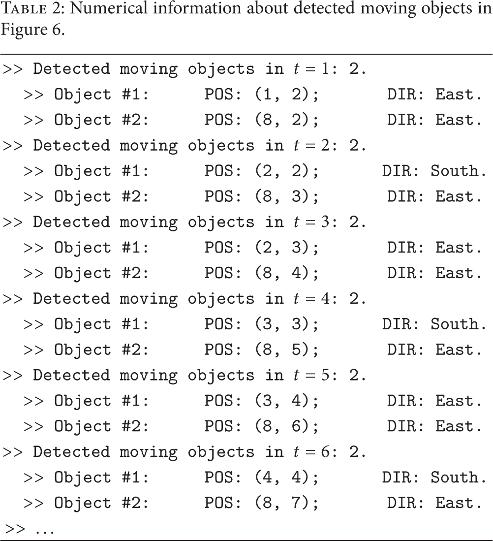
To illustrate its operation we will again use a simple example. Consider a square moving diagonally (from the upper left to the lower right corner) and a smaller square moving East. The complete application pathway for the object tracking (including partial and complete edge, object, and motion detection) is graphically and numerically shown in Figure 6 and Table 2.
Numerical information about detected moving objects in Figure 6.

Illustrative example of the object tracking application.
The observed results show that the NSN approach is a viable proposal to achieve application scalability in WSNs. It shows how applications can be constructed in a hierarchical, distributed, and scalable way in order to reuse already existing processing units in many different applications within a set of existing WSNs.
5. Real Deployment of the NSN Platform
We have implemented the NSN platform described in Section 3 in a real application deployed in the cities of Madrid and Seville (Spain) which monitors road traffic based on detecting Bluetooth devices.
5.1. Bluetooth-Based Vehicle Detection
Novel intelligent transportation systems (ITS) include automatic vehicle identification (AVI) platforms capable of detecting a vehicle in different points of a road or a city. These AVI systems provide detailed information like travel times (TTs) of road segments, origin-destination matrices, and so forth, highly useful for traffic managers, municipalities, and drivers.
In collaboration with Sociedad Ibérica de Construcciones Eléctricas (SICE), worldwide leader in ITS, we developed an AVI system based on detecting the Bluetooth device embedded in every modern vehicle. The system collects the identifiers of the Bluetooth devices and the time stamp of the detection. Then it looks for consecutive detections of the same vehicle, eliminates outliers, and generates its TT in a specific stretch. For a certain time slot, the system finally calculates its most representative TT, by processing the set of collected TTs produced by the different vehicles. This information is available for the end user on a web page.
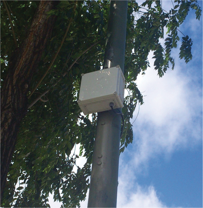
We deployed a first phase of this system in the cities of Madrid and Seville (Spain). Figure 7 shows one of our Bluetooth detectors installed on a streetlight. We are currently extending the system in Madrid to a broader area, following a grid deployment of the Bluetooth. This new setup will require growing the existing applications in order to tackle problems like building origin-destination matrices among others.

Bluetooth detector.
5.2. Real NSN Implementation
This system implements the NSN platform described in this paper. The sensor detects Bluetooth devices and sends the relevant data (identifier and time stamp) through the bridge server, which currently uses a 3G dedicated link. Each time a new Bluetooth detection is performed, the dispatcher posts an event to a PU devoted to matching individual time stamps. Once this PU finds two consecutive time stamps of the same vehicle it generates an output with this information that is then consumed by a second PU responsible for eliminating outliers; this PU compares the received TT with the TT profile of the preceding valid detections; if it fits with the TT profile, it publishes this information; if not, it discards it. The last PU takes all the valid TTs generated during a specific time slot and calculates its representative TT measurement. Finally, this information is fed back to the outlier removal PU in order to update its TT profile and the corresponding algorithm.
The user interacts with the system in two different ways depending on the user profile. The NSN managers access the system through the object server in order to configure a set of parameters: device identifier, location, and transmission power. The actual implementation of the object server relies on a web service that provides geographical functionalities to the NSN managers. On the other hand, the drivers or any other interested user can access the TT information provided by the corresponding PU through a web page that displays it both as a color (green, yellow, red, and black) of the stretch and a dashboard. Figure 8 shows the web interface for drivers and users.
NSN traffic monitoring and information web page.
5.3. Evolution
The neuromorphic nature of the NSN we have built for traffic monitoring and information allows us to evolve it in the very near future. Apart from the extensions in size we have previously mentioned, we will deploy a second set of sensors to monitor environmental variables such as temperature, humidity, noise, and pollution. These parameters will then be correlated with traffic measurements in order to construct the empirical impact of traffic on the city. The main contribution of this new type of information will be its spatial density (much larger than the one reached by the current meteorological stations) and its continuous monitoring in time.
6. Conclusions
WSNs can currently use many different clustering approaches in order to group together their sensors in a hierarchical and more efficient way to scale in size and number. However, the application scalability, that is, developing a growing set of applications that can be performed by a single WSN, is yet unresolved.
The operation of vertebrate sensory systems, which creates pathways to build specific functions, provides an optimal approach to achieve this goal. The processing architecture and communications in a WSN can be designed to mimic this operation. Consequently, we have constructed a NSN platform that provides the capability of creating pathways of already existing PUs to perform specific functions and reach the desired application scalability.
This NSN platform is currently implemented as the basis of a traffic monitoring and information system, deployed in a real scenario in the cities of Madrid and Seville. Following the NSN principle, the NSN platform allows us to construct new applications on top of the already existing physical sensor network to create the empirical connection between traffic and environment in a city.
Footnotes
Conflict of Interests
The authors declare that there is no conflict of interests regarding the publication of this paper.
Acknowledgments
This research was partially funded by projects COMPAS (IPT-2012-0497-390000) and PLASMA (RTC-2014-2158-4) funded by the Spanish Ministry of Economy and Competitiveness (INNPACTO and RETOS).