
Abstract
IEEE 1609.4 defines MAC layer implementation in a vehicular ad hoc network (VANET). In IEEE 1609.4 multichannel operation, the control channel interval (CCHI) and the service channel interval (SCHI) are defined such that service channels cannot be utilized during the CCHI, and vice versa, which leads to poor utilization of scarce spectrum resources. In this paper, we propose a multi-schedule-based channel switching mechanism to improve channel utilization and uniformly distribute channel load. In our proposed mechanism, four schedules are defined to switch between the control channel and service channels. Therefore, service channels can be utilized during the CCHI, and the control channel can be utilized during the SCHI. Moreover, control channel load is distributed throughout the whole sync interval. We compared our proposed MAC protocol with IEEE802.11p for wireless access in the vehicular environment using the OMNET++ 4.5 network simulator. In the simulation results, we determined that utilization of the service channel increased and contention on the control channel was reduced, compared with the legacy standard, especially in slow motion and high-density VANETs.
1. Introduction
Day by day, the number of vehicles in use worldwide is dramatically increasing, which creates a greater potential for traffic accidents. The US government officially announced that intelligent transportation systems [1] related especially to vehicle-to-vehicle (V2V) research must turn into action. V2V technology can minimize many potential traffic hazards and prevent many accidents by exchanging crucial information between vehicles which is obtained by sensing a vehicle's situation, driver's health condition, road condition, surrounding vehicles, and so on. V2V communications use the dedicated short-range communication (DSRC) 5.9 GHz [2] frequency band, which is a limited spectrum source. In the DSRC band, seven channels are defined, and each bandwidth is 10 MHz wide. Among these channels, the one dedicated to safety messages is called the control channel (CCH), and the remaining six channels are dedicated to infotainment services, each called a service channel (SCH).
Under IEEE 802.11p for wireless access in the vehicular environment (IEEE802.11.p/WAVE) multichannel operation [3, 4], time is divided into 100 ms, each of which is called a sync interval that has a control channel interval (CCHI) and a service channel interval (SCHI) of 50 ms lengths. The CCHI transmits safety messages, and the SCHI transmits nonsafety messages. Safety messages are categorized into routine messages, which in our proposed mechanism we call beacon messages, and real-time occurrence messages, which we call emergency messages. For instance, nodes need to frequently advertise their presence to nearby nodes. For this purpose, nodes periodically broadcast a beacon message, which consists of the node's current situation, velocity, location, and other information. Obstacles on the road, driver's unstable condition, or sudden vehicle breakdowns and so forth generate an emergency message. All messages have priority access to channels depending on their type. For instance, safety messages have a higher priority than nonsafety messages, and emergency messages in particular have the highest priority. The legacy IEEE 802.11p/WAVE standard uses an enhanced distributed channel access (EDCA) [5] mechanism to manage message priorities, known as access categories (AC).
All nodes need to switch between the CCH and SCHs every 50 ms. During the CCHI, nodes transmit or receive safety messages on the CCH, but the other six SCHs are not utilized and vice versa, as shown in Figure 1. The multichannel operation design displayed below is not an efficient usage of scarce spectrum resources. In V2V communication networks, to improve traffic safety, large amount of sensing data such as road surface situation, vicinity traffic condition, driver's liability, and vehicle's stability, is needed to be delivered and disseminated to vehicles. Hence, channel resources must be used smartly and in an efficient way.
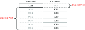
Channel switching and usage of the CCH and SCHs under the conventional standard.
Many existing studies have worked on ways to overcome this drawback and to improve channel throughput. For instance, Zhang et al. [6], Bejaoui [7], and Yao et al. [8] focused on increasing channel throughput by adopting an adaptive CCHI depending on network density and a time division multiple access (TDMA) mechanism. However, there is still channel waste because SCHs are not utilized during the CCHI. Wang and Yu [9] and Hafeez et al. [10] implemented a cluster-based scheme to improve channel utilization.
When the CCHI starts, all nodes try to access the CCH to transmit safety messages, which causes congestion on the CCH, especially in high-density networks. During the SCHI, nodes prepare their beacon messages periodically, which become congested in the EDCA queue. Other researchers [11–13] mainly focused on reducing congestion on the CCH by adopting dynamic contention window size and transmission power. However, these methods have their own limitations. For example, in cluster-based networks, processes are needed for choosing cluster heads and for handover between clusters, which are not suitable for fast-changing vehicular networks. And congestion-control-mechanism-based approaches do not lower channel idle time. Therefore, we worked on a way to improve channel utilization, to distribute channel load uniformly and to mitigate channel congestion.
In this paper, we propose a novel multichannel medium access control (MAC) mechanism by adopting multiple schedules to switch between the CCH and the SCHs. In our proposed mechanism, four separate periods of time are defined to access the CCH. In other words, four different time schedules are defined for switching between the CCH and the SCHs. Therefore, not all nodes try to access the CCH at the same time, as in legacy IEEE802.11p/WAVE. As a result, we can mitigate congestion on the CCH. Besides, due to nodes having different time schedules to switch between the CCH and the SCHs, when some nodes are on the CCH, other nodes are on an SCH. Hence, there will be no channel waste, unlike under the conventional standard.
The rest of this paper is organized as follows. In Section 2, the proposed mechanism is demonstrated in detail. In Section 3, the process of propagating emergency messages and data transmission on the SCHs is demonstrated. In Section 4, we introduce our simulation environment, the proposed mechanism is compared with the conventional standard, and simulation results are provided. Finally, Section 5 concludes this paper.
2. Multi-Schedule-Based Channel Switching Scheme
In this section, we present our proposed multi-schedule-based channel switching (MSCS) mechanism in detail. Figure 2 shows usage of channels during the sync interval in our mechanism, where SCHs are utilized during the CCHI and the CCH is utilized during the SCHI, unlike the conventional standard as depicted in Figure 1.

Usage of the CCH and SCHs under the proposed mechanism.
In our proposed protocol, the concept of phase is the same as group of nodes. Four phases are defined, each having a different time schedule to switch between the CCH and the SCHs, which allows use of the channels all the time. Which phase a node is going to use depends on when the node first accessed the CCH. We will explain this procedure in the following subsection. Then, the process of synchronizing the presence of neighbor nodes will be presented. After that, we will demonstrate the process of selecting a service channel.
2.1. The Process of Defining Phases of Nodes
As we mentioned, in our system, four phases are defined, and each phase has a schedule for channel switching. The schedule determines when to switch between the CCH and the SCHs. Nodes determine their phases based on the time they first accessed the CCH. In the IEEE 802.11p/WAVE standard, a sync interval has a CCHI and a SCHI, and the length of each is 50 ms. The CCHI and SCHI are equally subdivided into two parts, and the length of each part is 25 ms. When a node joins a network for the first time, it tunes to the CCH and tries to access it. After accessing the CCH, it determines its “phase” by calculating the time it accessed the CCH using the algorithm given in Figure 3, where ms indicates the last two digits of the milliseconds of the actual coordinated universal time the node accessed the CCH.
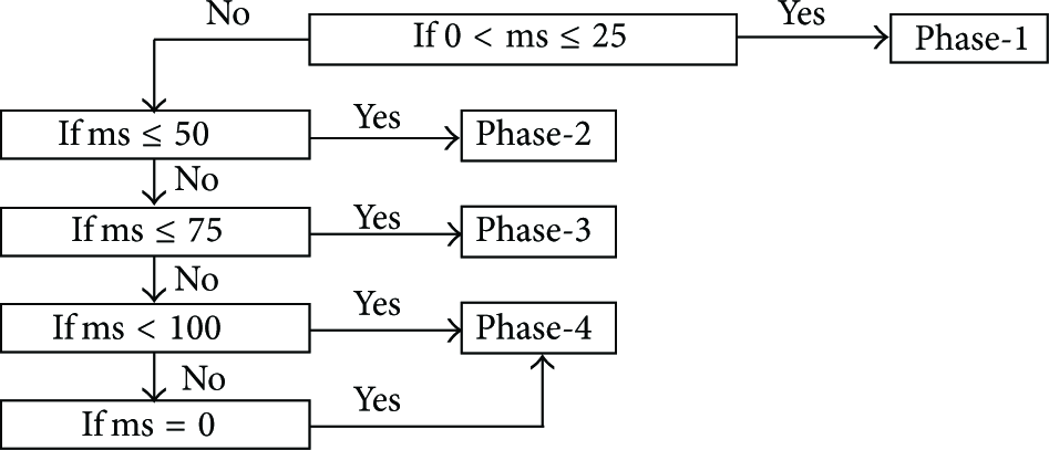
Algorithm for determining phase.
If the access time of the node is during the first 25 ms of a sync interval, it becomes a member of phase-1, and if the access time is between 25 and 50 ms, it becomes a member of phase-2. The same concept applies to membership of phase-3 and phase-4, as illustrated in Figure 4.

Process of defining phases and an illustration of the CCH's utilization of phases.
Another simple method that we could implement in the process of defining the phase is when the number of nodes within communications range is little; then, we can simply assign phases uniformly to nodes without using the algorithm given above. The main idea of this proposed mechanism was inspired by the concept of the above algorithm.
After a node determines its phase, it will include this information in a beacon message and it broadcasts it. Once the node knows its phase, it will follow its phase's channel switching schedule, which is illustrated in Figure 5.

Channel switching intervals of the phases.
2.2. Synchronizing the Presence of Neighbor Nodes
A node senses its vicinity traffic condition by accumulating routine messages from nearby nodes. In other words, nodes periodically advertise their presence by broadcasting beacon messages, and all nodes within communications range receive them. However, in our proposed scheme, when some nodes broadcast their beacon messages on the CCH, other nodes are on an SCH, as illustrated in Figure 5. Hence, they cannot receive those beacon messages. In other words, they cannot sense theirs surrounding traffic situation. Therefore, we implement a procedure that can synchronize the presence of surrounding nodes by using relay and piggyback mechanisms. We can conclude from Figure 5 that a phase is a period of time to utilize the CCH, the length of which is 50 ms, and we can see that some phases overlap, but some do not.
As illustrated in Figure 4, a phase is subdivided into listen and access periods, each with a length of 25 ms. When some nodes are in the listen period, other nodes are in the access period. Splitting the phase into listen and access periods allows them to transmit and receive beacon messages with fewer collisions, because nodes in the listen period only listen, while nodes in the access period broadcast their messages. When nodes broadcast their beacon messages, they piggyback other beacon messages that were received from other nodes on the CCH during the access period, as depicted in Figure 6, where

Illustration of synchronizing the presence of neighbor nodes.
In Figure 7,

Circle of synchronizing the presence of neighbor nodes.
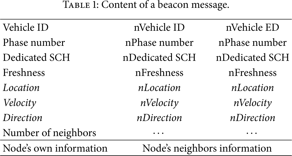
When a node broadcasts its beacon message, it includes its phase number and its dedicated service channel number in addition to the vehicle's current velocity, position, number of neighbors, and other information. A beacon message is depicted in Table 1. Attributes in normal font are mandatory information, whereas attributes in italics are optional.
Content of a beacon message.
2.3. The Process of Selecting Service Channels
In the IEEE802.11p/WAVE standard, seven channels are defined. One of them is the control channel and the remaining six are service channels. All nodes have to choose one SCH on which to transmit infotainment data during the SCHI, which in our protocol we call the dedicated SCH. A node chooses only one SCH as its dedicated service channel from among six SCHs. The process of selecting dedicated SCHs depends on the node's purpose. When a node chooses its dedicated SCH, it will consider two aspects of the SCHs. The first is how many current users it has, and the second is how much the SCH is being utilized at the current time. If the node's purpose is to achieve high throughput, then it will consider the utilization of SCHs and select the SCH being used the least. If the node's purpose is to disseminate its data to a lot of nodes, then it will evaluate the number of current users of SCHs and pick the SCH that has the most users. After selecting a dedicated SCH, when a node broadcasts its beacon message during the access period on the CCH, it includes its dedicated SCH information in the message, as shown in Table 1. Therefore, neighbor nodes become aware of theirs dedicated SCH. All nodes have a neighbor information table that contains necessary information about their neighbor nodes, such as usage information of the SCHs. When a node receives a beacon message, it will store the essential parts (such as dedicated SCH) in its neighbor information table, as illustrated in Figure 8. Therefore, nodes can easily evaluate the characteristics of SCHs from their neighbor information tables.
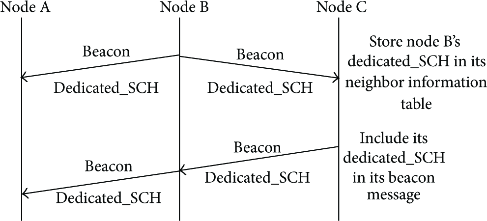
Illustration of broadcasting and storing the dedicated SCH.
3. Propagating Emergency Messages and Nonsafety Data Transmission
In V2V communication networks, sensing emergency data is crucial to providing traffic safety and reducing potential traffic accidents. Therefore, emergency data needs to be immediately delivered to surrounding nodes after it is initiated. Emergency data message is urgent event information created by a node in real time. In other words, emergency messages can be initiated by any node at any time; hence, we have to implement dissemination of an emergency message differently, depending on when it was initiated.
There are three types of scenarios based on the period in which emergency message was initiated. The first scenario is an emergency message triggered during the access period of the CCHI; the second scenario is an emergency message initiated during the listen period of the CCHI; another scenario is an emergency message created during the SCHI.
3.1. The Process of Propagating Emergency Messages
As mentioned in the previous section, when some nodes are on the CCH, other nodes are on SCHs owing to their use of different channel switching schedules. In other words, when a node broadcasts an emergency message on the CCH, nodes that are on SCHs cannot receive it, and vice versa, which means some nodes cannot sense emergency data. Therefore, we need to implement a procedure that can disseminate emergency messages to all surrounding nodes regardless of the channel they are working on. Employing this kind of procedure, all nodes in the communication range are able to sense emergency data right away.
Scenario-1, where the emergency message is initiated during the access period of the CCHI, is shown in Figure 9, where

Propagating emergency messages on the CCH during CCHI.
In Scenario-2, the emergency message is initiated during the listen period of the CCHI. In this case, the initiator will wait until the access period starts because, during the listen period, nodes are not allowed to transmit any messages, and the rest of the procedure is the same as in Scenario-1. After the initiator broadcasts its emergency message on the CCH and the access period is finished, it switches to its dedicated SCH and rebroadcasts the emergency message. Thus, nodes that are listening on the same SCH will receive it, as shown in Figure 10, where
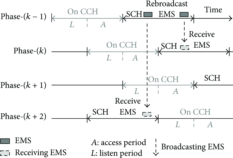
Propagating emergency messages using the dedicated SCH during CCHI.
In Scenario-3, the emergency message is initiated during the SCHI. In this case, the initiator immediately broadcasts the emergency message on its dedicated SCH. After that, it switches to the SCH that has the most users and rebroadcasts its emergency message. Then, the initiator switches to another SCH that has the second highest number of users and rebroadcasts its emergency message. This process will continue until the emergency message is broadcasted on all SCHs or until SCHI ends. Examples are shown in Figure 11.

Illustrations for propagating emergency messages on SCHs.
In Figure 11, N1 is the initiator, and its dedicated SCH is five, which means the initiator will first broadcast its emergency message on SCH5. Then, it will estimate which SCH has the most users from its neighbor information table. In this case, that SCH is SCH1, because N2, N3, and N5 are using SCH1; hence, the initiator will switch to SCH1 and rebroadcast its emergency message on SCH1. After this, the initiator will find the SCH that has the second highest number of users, which in our example is SCH3. Because N4 and N7 are using SCH3, the initiator will switch to SCH3. If there is still time until the switch to the CCH, then the initiator will switch to the next SCH, based on the same concept. When more than one SCH has the same number of current users, the initiator randomly chooses an SCH. After the SCHI finishes, the initiator switches to the CCH and waits until the access period starts, because nodes are not allowed to broadcast any messages during the listen period, as illustrated in Figure 12. Once the access period starts, the rest of the procedure is the same as that demonstrated in Figure 9.

Illustration of propagating emergency messages on SCHs.
3.2. The Process of Nonsafety Data Transmission
Nonsafety infotainment data transmission is an important function in VANETs. Infotainment data transmissions take place on SCHs during the SCHI. Under the conventional standard, to transmit infotainment data, nodes must exchange request to send (RTS) and clear to send (CTS) packets on the CCH during the CCHI, which is not a highly efficient solution in high-density networks because of congestion on the CCH. Therefore, we came up with the dedicated SCH concept, which means a node receives nonsafety data on only one SCH and discards the RTS/CTS scheme. When a node needs to transmit nonsafety data to another node, the sender will use the receiver's dedicated SCH. Every node has its dedicated SCH, and neighbor nodes have this information. If one node has data for a certain node, the sender will switch to the receiver's dedicated SCH and transmit them. After a receiver successfully receives nonsafety data, it will send an acknowledgement (ACK) packet on its dedicated SCH, as illustrated in Figure 13.

Illustration of data transmission on an SCH.
Another case of nonsafety data transmission on SCHs is that a node, which we call the receiver, initiates infotainment data transmission by sending a data request packet. First, the receiver will switch to the sender's dedicated SCH and transmits a data request packet to the sender on the sender's dedicated SCH. After the sender successfully receives the data request packet, the sender will transmit the requested nonsafety data to the receiver on its dedicated SCH. Subsequently, after the receiver successfully received the data packet, it sends an ACK packet on the receiver's dedicated SCH, as demonstrated in Figure 14.

Illustration of data transmission on an SCH with a data request packet.
The process of nonsafety data transmission on an SCH illustrated in Figure 14 is only attempted between overlapped or same-phase nodes. This process is inapplicable to a scenario where infotainment data transmission is between nodes that are not members of overlapped phases. Nodes that are not members of overlapped phases can transmit nonsafety data employing a smart routing and forwarding mechanism. We will develop this in future work.
4. Simulation Environment and Results
In this section, we explain our simulation environment. As mentioned in the abstract, our proposed mechanism is suitable for slow-motion and high-density congested networks, such as an urban traffic jam or big intersections. During rush hour, traffic congestion often occurs at a certain point. We used network simulator Omnet++ 4.5 to experiment with our proposed mechanism. In our simulation network, all nodes move in one direction with one lane at a different speed. Our simulation road is rectangular with a 1 km length on each side and no obstacles on the road. Every node's position is randomly chosen. Speed of the nodes is randomly chosen from a range between 20 kmph and 72 kmph, depending on how much of the road is congested, and does not change during the simulation. For instance, if there are fewer than 50 nodes within communications range, which is 500 meters, speed will be chosen between 57 kmph and 72 kmph. If there are more than 100 nodes, then the range is 32 kmph to 64 kmph, and if there are more than 150 nodes, the speed will be chosen from between 20 kmph and 36 kmph. All messages have the same transmission range; for instance, beacon messages and emergency messages have the same transmission range. In Table 2, the parameters used for the simulations are given.
Parameters used for simulations.

We compared our multi-schedule-based channel switching (MSCS) MAC protocol against the IEEE802.11p/WAVE standard. We analyzed the performance of the channels (for instance, utilization, success rate of receiving packets and collision probability, etc.). In our proposed system, as introduced in the previous section, by adopting MSCS, we can utilize the CCH and the SCHs regardless of the current interval. In other words, during the CCHI, all SCHs can be utilized, and vice versa. Therefore, channel idle time is greatly reduced and channel load is uniformly distributed throughout the channels. This is analyzed in Figure 15, which shows the comparison of patterns of broadcasting periodic safety messages in IEEE802.11p/WAVE and under the MSCS protocol. In the legacy standard, the space between patterns is huge which means, in that period of time, the CCH is not utilized. Meanwhile, under MSCS, patterns are uniformly distributed which indicates that load of CCH is distributed throughout the time of utilization.
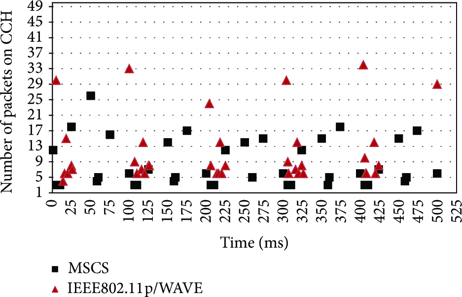
Safety message broadcasting pattern.
In Figure 16, utilization of the SCHs has been compared. As we can see, when the number of nodes in communication range is low, the load on SCHs is not much; however, utilization of SCHs increases as the number of nodes in communication range increases. In our proposed protocol, the utilization of SCHs is about doubled compared with that of the conventional standard. In the conventional standard, nodes utilize SCHs only during the SCHI, whereas, under MSCS, nodes utilize SCHs during whole sync interval, which leads to improving service channels throughput and utilization.

Channel utilization of SCHs.
In Figure 17, the collision probability of SCHs has been analyzed. In our proposed protocol, the collision probability of SCHs is much lower than that of the conventional. The reason is, in legacy systems, nodes utilize SCHs only for half of the sync interval, whereas, under MSCS, nodes utilize the SCHs for the whole sync interval. Hence, the load on the SCHs is uniformly distributed throughout the whole sync interval. That is why, in our proposed protocol, collision occurrence is much lower than with the conventional standard.

Collision probability of SCHs.
In Figure 18, the collision probability of the CCH has been analyzed. You can see that the legacy standard is lower than MSCS. In our proposed scheme, nodes broadcast their beacon message during its access period, the length of which is 25 ms; therefore, collision could occur more comparing with conventional standard. Another reason that impact on collision on the CCH is piggybacking mechanism that we implemented. As we mentioned in an earlier section, some phases do not overlap each other, and, hence, we implemented a procedure that synchronizes neighbor awareness by piggybacking received beacon messages. In this procedure, nodes include a neighbor node's information in its beacon message and then broadcast the message, which could lead to increasing beacon message packet size. Therefore, as network grows, nodes piggybacking message size increases and increased packet size can be a cause of additional collision.

Collision probability of the CCH.
In the previous section, we mentioned that some phases do not overlap. So, we used the process of synchronizing an awareness of neighbors and analyzed how adequately it works. The result of the process is depicted in Figure 19. As shown in the graph, when the number of nodes within communications range is more than 20, the result of the process is promising. However, when the number of nodes within communications range is less than 20, we have insufficient candidates to relay packets. Hence, a node cannot synchronize with another phase's members. In other words, a node possibly might not be aware of the presence of its surrounding nodes. This is the reason that our proposed mechanism is suitable for a dense network.

Percentage of neighbor awareness.
5. Conclusions and Extensions
In conclusion, we propose a multi-schedule-based channel switching MAC protocol for dense networks, and we analyzed our system. We adopted four schedules to switch between the CCH and the SCHs in order to improve utilization of channels and reduce channel overload. In the simulation results, we showed that our proposed protocol outperforms the conventional standard in a high-density network. In our proposed mechanism, utilization of the SCHs is surprisingly increased, the collision rate is lower, and the packet loss rate is also reduced, as illustrated in the previous section.
Our proposed mechanism has some limitations. As explained, some phases do not overlap; for example, when phase-1 is on the CCH, phase-3 is on the SCHs. As a result, if a member node of phase-1 wants to transmit infotainment data on SCHs to other nodes of phase-3, the phase-1 member has to change its phase or use a smart forwarding packet mechanism. Unfortunately, in this simulation, we could not develop this kind of mechanism, but we will develop this improvement in our future work.
Footnotes
Conflict of Interests
The authors declare that there is no conflict of interests regarding the publication of this paper.
Acknowledgments
This work was supported by the Inha University Research Grant. This research was supported by Basic Science Research Program through the National Research Foundation of Korea (NRF) funded by the Ministry of Science, ICT and future Planning (NRF-2014R1A2A2A01002013). This research was supported by the MSIP (Ministry of Science, ICT and Future Planning), Korea, under the ITRC (Information Technology Research Center) support program (NIPA-2014-H0301-14-1042) supervised by the NIPA (National IT Industry Promotion Agency).