
Abstract
This paper presents an intelligent power outlet system that can be controlled wirelessly and that has been specifically designed to monitor electrical events in low-current loads. Each power outlet of the system embeds a microcontroller, a 2.4 GHz ZigBee interface, RFID (Radio Frequency Identification) reader, a relay, and a current sensor. The main features of the system include the remote control of the power outlet, real-time monitoring of the current consumption, the customization and programming of the power supply time schedule, the automatic interruption of vampire currents, and the prevention of certain types of electrical fires and electrocutions. A prototype with such features has been implemented and tested in a simple home automation network in order to validate its functionalities. The results show that the system reacts fast and avoids overconsumptions and electrocutions, being able to make the next generation of homes safer and smarter.
1. Introduction
Modern homes provide electricity to electrical devices through the last element of the power supply chain, the power sockets, which have been regarded traditionally as a mere junction. In fact, power sockets have not evolved as fast as other everyday devices, although they seem to be one of the best positioned candidates to be improved as smart homes are becoming increasingly popular.
In the last years, different functionalities have been added to power sockets, like wireless control or current consumption monitoring, but there are still many others that could make such devices smarter. This paper addresses some of the most common problems that arise when interacting with power sockets and shows a novel approach to two of them: the prevention of electrical fires and the avoidance of electrical shocks.
Regarding electrical fires, they are described as fires that begin because of some type of electrical failure or malfunction. The National Fire Protection Association (NFPA) [1] latest report states that, in 2011, just in the USA, there were 47,700 home electrical fires that resulted in 418 civilian deaths, 1,570 civilian injuries, and $1.4 billion in direct property damage [2]. In the same report it is also stated that, of all the electrical fires whose cause could be determined precisely, the vast majority were caused by short-circuits.
A similar situation occurs with electrical shocks. According to the Electrical Safety Foundation [3], in North America each day nearly 7 children are treated in hospital emergency rooms for electric shock or burn injuries caused by tampering with a wall outlet. In the same region, fires and burns are the third leading cause of unintentional death among children aged 14 and under.
In order to address the two issues previously mentioned this paper presents a smart power outlet system that has the following features:
It is able to detect overconsumptions that might lead to overheat in low-current systems and, therefore, to an electrical fire. It prevents electrocutions, since it only supplies power when it identifies a valid appliance. It can be controlled remotely using wireless sensor network technology. It is able to monitor in real-time and make available to external devices (e.g., PCs connected to the Internet, smartphones, and tablets) current consumption data. It can disconnect the power supply when a vampire current is detected (a vampire current is a current that arises when an appliance consumes power when it is in stand-by mode or when it claims to be switched off).
The next sections of this paper are structured as follows. Section 2 reviews the most relevant state-of-the-art smart power sockets developed with academic and commercial purposes. Section 3 details the design of the system and gives an overview of the communications architecture. Section 4 focuses on the description of the two main components of the system: the gateway and the smart power socket. Section 5 describes the functionalities and setup of the system implemented. Section 6 shows the results for different experiments that demonstrate the capabilities of the system. Finally, Section 7 is devoted to the conclusions.
2. State of the Art: Academic and Commercial Smart Power Sockets
2.1. Academic Developments
In the last years researchers have enhanced power outlets by adding different smart functionalities. For instance, [4] presented an outlet system that can be controlled remotely by using Bluetooth and GSM wireless interfaces. The system can switch every outlet on and off remotely by sending an SMS (Short Message Service). An improved version of the system is presented in [5], and it includes ethernet support and the capability of measuring current consumption. Furthermore, in [6, 7] almost the same authors of [4, 5] describe a similar outlet system with PLC (Power Line Communication) module. In the case of [7], the system is aimed at controlling remotely UPS (Uninterruptible Power System).
One of the first examples of wireless sensor networks applied to a power outlet system is described in [8]. The system proposed uses ZigBee to switch on and off remote outlets and to measure their current consumption.
A different approach is taken in [9]: the authors make use of a data acquisition system to control the state of the outlets and to monitor current consumption.
Another power socket system that uses ZigBee is detailed in [10]. Such a paper proposes communications architecture that allows for switching off a socket where an appliance in stand-by mode is plugged in.
Like in [6, 7], PLC interfaces are embedded into the designs proposed in [11, 12]. Both power outlet systems can switch on and off outlets and monitor current consumption, but the latter is especially interesting: it is able to use different sensors to monitor living patterns and then optimize the energy savings of a home.
The authors of the electrical outlet described in [13] embedded an ethernet module for a smart power grid in order to control the loads autonomously. Their system can switch on and off the power outlets, it is able to monitor current consumption, and it has been explicitly designed for working in a network where a large amount of the power comes from renewable sources.
Finally, [14, 15] present power outlet systems based on ZigBee and PLC, respectively. Such systems can control the state of the outlets and monitor current consumption, but the system detailed in [15] includes an additional feature: it is able to issue warnings about possible power overloads.
2.2. Commercial Smart Power Sockets
There are smart power sockets already available in the market (e.g., [16–22]), although, in general, they are a step behind the ones developed by researchers.
For instance, the WeMo switch from Belkin [16] is a WiFi-based power outlet that can switch on and off the power from an outlet. The MeterPlug [17] is similar but uses Bluetooth and it can also monitor current consumption. MyPlug, from Orange [18], has ZigBee transceiver and GSM interface, but it is only able to control the state of the power socket.
The SafePlug [19] is probably one of the most advanced off-the-shelf developments: it can switch on/off the power, monitor current consumption in real-time, and identify appliances to prevent fires and electrical shocks.
Finally, it is worth mentioning three other solutions: PlugWise [20], Modlet [21], and SmartPlug [22]. They all have very similar functionalities (they can switch on/off the outlets and monitor energy consumption), but while PlugWise and SmartPlug use ZigBee, Modlet seems to use a proprietary wireless technology.
2.3. Analysis
After analyzing all the references previously mentioned, it can be stated that the enhancements performed over power outlets have been mainly focused on the ability to control them remotely, by using wired [6, 9, 11–13, 15], wireless [4, 7, 8, 10, 14, 16–22], or hybrid interfaces [5]. Most of the wireless power outlets only carry out point-to-point communications (e.g., [4, 5, 7, 16, 17]), using technologies like Bluetooth [4, 5, 7, 17], GSM [4, 5, 7, 18], or WiFi [16].
However, in the last couple of decades, different alternatives were proposed in order to substitute point-to-point networks for sensor networks. The first sensor networks were initially used in environments where there had to be a strict control of specific parameters like temperature, humidity, or the presence of toxic gases. These kinds of networks could either use independent wired infrastructure (e.g., KNX [23] or LonWorks [24]) or the already existent infrastructure (e.g., X10). Other alternative communication technologies that have achieved certain degree of success on the market are BACnet (Building Automation and Control Network) [25], DALI (Digital Addressable Lighting Interface) [26], EnOcean [27], Z-Wave [28], DASH7 [29], and Wireless HART [30].
The latest evolution of sensor networks is Wireless Sensor Networks (WSNs), which have been thoroughly studied for their application in different fields [31], from wearable computing [32] to the management of the power grid [33], or even to musical activities [34].
Currently, ZigBee is arguably the most popular technology for creating WSNs and it has been included in the latest generation of wireless power outlets [8, 10, 14, 18–22].
Although ZigBee is a well-established technology, it is worth mentioning that the ZigBee Alliance has been working recently on an open alternative (ZigBee IP [35]) that includes IP connectivity through 6LoWPAN (IPv6 over Low-Power Wireless Personal-Area Networks) [36]. There are several manufacturers that are already selling ZigBee IP-compliant platforms. Such IP connectivity seems to be one of the keys for the future Internet of Things (IoT) [37] and will enable the interaction among the increasing amount of IP-enabled devices present in modern homes (e.g., smart televisions, home entertainment equipment, and remotely controlled appliances).
Besides WSNs, energy efficiency is probably one of the most studied topics in the field of intelligent homes, and some of the smart power outlets previously cited have been presented with the objective of monitoring energy consumption [17, 19–22].
Related to home energy efficiency is the problem of vampire currents. Surprisingly, just a few smart power outlets [10, 17] automate the detection of vampire currents and are able to disconnect appliances after they have been in stand-by for a certain amount of time.
Regarding electrical fires and electrical shocks, there is barely any commercial or academic smart power outlet specifically addressed to tackle them. The exception seems to be SafePlug [19]. However, after analyzing all the academic and commercial devices, it has been found that none implements all the functionalities offered by the system presented in this paper.
3. Design of the System
Traditionally it has been stated that, for the protection of electrical installations and people, there is a well-established array of tried and tested hardware technologies (e.g., fuses and circuit breakers) that are safe and fast. Although such technologies achieve their goal when configured properly, they usually do not adapt dynamically to the environment or to the connected appliances.
The system presented in this paper involves the use of software control, which has been regarded as relatively slow and subject to software errors. The latter statement can be tackled by performing intensive tests under harsh conditions, but the former needs to be studied carefully before implementing an electrical safety software-based device.
3.1. On the Prevention of Electrical Fires
Electrical fires can occur due to different events, with two of the most common ones being power overloads and short-circuits. In both cases, when they happen, the energy released must be smaller than the maximum load capacity of the transmission medium to avoid irreparable damage.
In the case of power overloads, the current must remain below the maximum permissible load current of the transmission medium (

In the case of short-circuits, it is necessary to determine the maximum short-circuit current. If the short-circuit release time is under 100 ms, the next rule is usually followed to prevent electrical fires and avoid damage [38]:

Equation (2) indicates that if a high current is maintained during too much time, the conductor through which it flows might be melted and even catch on fire.
Such equation in (2) is derived from thermodynamic equations that regulate adiabatic processes and it enables designers to check the suitability of a composite cable used for the c.p.c. (circuit protection conductor, i.e., the earthing conductor and all the equipotential bonding conductors). Equation (2) can be rewritten to determine the maximum time required to damage a cable:


Equation (4) can be simplified by assuming a particular type of conductor:

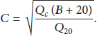
For instance, C for copper is 226 and for aluminum is 148 and for steel is 78 and for lead is 41.
Therefore, once the conductor material has been chosen, the value of K will depend solely on the initial and final temperatures supported by the insulation. For example, K becomes 115 for a cable made of copper (B for copper is 234.5°C) and insulated with p.v.c. when assuming
Then, according to (3), Figure 1 plots t for different values of

Maximum release times before damage under 20 ms for different materials, insulations, and cross sections.
Therefore, it is possible that an appliance results in severe damage and catches on fire before a regular MCB stops the current flow.
Finally, it is worth mentioning that (2) assumes that all the heat generated during a short-circuit is retained, which, in reality, does not occur, but it allows for obtaining a conservative estimation that provides a safety margin. If more precision is required, nonadiabatic heating must be considered [40].
3.2. Time Constraints for Software-Based Current Monitoring Devices
In the case of systems that perform an active monitoring of the current in order to prevent certain events, what might concern users is the amount of time the system needs to react. Such an amount is given by

The detection time can be decomposed in the following terms when the detection is performed through a software algorithm:

Regarding the term

Since a smart outlet would be placed after a regular home circuit breaker, it has to react at least as fast. For low-load currents (under 100 A) MCBs are commonly used. The time required to switch the breaker contacts in MCB usually oscillates between 20 ms and 50 ms; therefore, it will be established as a reference that the detection time
Before designing the device, the hardware-related times
The time required to switch off the power supply (
In order to perform a fair comparison between relays and circuit breakers it is also important to note that the former ones usually include in their datasheets time curves that are used to show how fast a breaker will trip at any magnitude of current. It can be observed in such curves that the larger the current is, the faster the breaker will switch and, therefore, the shorter the trip time is. The trip time can be defined as the time required to open the circuit once it has sensed an event. By comparing commercial MCB datasheets it can be concluded that the trip time is at least equal to 3 ms for a current that is 3 times the nominal current.
3.3. On the Prevention of Electrical Shocks
Power outlets usually include different safety measures in order to prevent electrical shocks. The most common one is the addition of a third prong (ground) that reduces the risk of electric shock and protects equipment from electrical damage. There are also power sockets that are encapsulated into a tamper-resistant receptacle that prevents the insertion of objects. There are also power outlets (AFCI, Arc Fault Circuit Interrupters) that reduce the risk of electrical shock by interrupting power when arc fault occurs in the circuit. Moreover, there is another kind of outlets (GFCI, Ground Fault Circuit Interrupters) that prevents shocks by shutting off the power when the electricity flowing into the circuit is superior to the one returning (i.e., when there is a leakage).
All these traditional solutions work in most situations, especially when the same outlet combines different functionalities (e.g., ground fault protection and tamper resistance), but there are still cases when they fail (e.g., when the ground is not properly set or when a kid is able to tamper the outlet).
The system proposed in this paper prevents electrical shocks based on the following principle: if there is no appliance connected to the outlet, electricity will not be supplied. In this way, most of the tampering will have no consequences and no electrical shocks should occur.
To achieve this goal it is necessary to identify when an appliance is connected to an outlet. There are different mechanisms that allow for identifying appliances, but most of them rely on mechanical systems, nonautomated systems (e.g., pressing a button to indicate that the appliance is connected), or proprietary technologies. The proposed solution uses RFID (Radio Frequency Identification): RFID reader is embedded into the power outlet, while RFID tags are attached to the appliance electrical connector or to its cord. Therefore, electricity is only supplied if a valid RFID tag is attached to the appliance and if its connector/cord is very close to the smart power outlet (within several centimeters).
Regarding electrical shocks caused by arc faults, they are mostly suppressed by using the design principles detailed in Section 3.1.
3.4. Communications Architecture
In an automated home, the domotic installation is ideally deployed during the construction stage, in conjunction with the deployment of the electrical system. However, in houses and buildings recently built but not explicitly designed for incorporating domotics, the electrical infrastructure could be added later, which might become a really cumbersome task and, in some cases, even impossible.
This problem can be tackled by using wireless power outlets interfaces, which can be placed whenever the user wants (not necessarily during the construction stage) and that do not require altering the internal decorations or modifying the internal wiring of the house. For such a reason, the system presented in this paper incorporates wireless communications module. In fact, it is incorporated wireless sensor network module since it allows for extending the communications range just by adding relay nodes. This is key indoors, where the regular range in the 2.4 GHz band reaches between 40 and 100 meters. Furthermore, some construction materials like concrete or certain metallic structures alter signal propagation, deriving into its attenuation and, in consequence, into a remarkable decrease in wireless coverage. Thanks to the ability of relaying the wireless signals received from other sockets, the communications towards and from a gateway can easily reach several hundred meters.
Figure 2 shows the communications architecture of the system proposed. Each smart power outlet is able to transmit and receive data directly to/from a central gateway or by using intermediate power outlets. The gateway is responsible for connecting the power outlet system to a wide variety of remote devices that may be attached to the Internet.

Overview of the communications architecture proposed.
This communications architecture is possible thanks to the use of WSN technology like ZigBee. ZigBee is actually a set of wireless protocols for performing low-energy consumption and low data rate communications. A deep description of ZigBee is beyond the scope of this paper, but the interested reader can refer to [41] to get a good overview on the basics of ZigBee.
4. Components of the System
As it can be observed in Figure 3, the system consists of two main components: the smart sockets and the gateway, which are described in the next subsections.

Main components of the smart power socket system.
4.1. Gateway
The gateway is responsible for exchanging information with the smart sockets and for making the data available to remote users through a web application. Its hardware consists of two subsystems dedicated to tasks related to control and communications.
4.1.1. Control Subsystem
It is made of two main components:
The web application. It allows users to configure and interact with each individual power socket. It is currently running on a PC, but it could be easily embedded into smaller platforms. The ZigBee interface. It is connected through USB to the PC that runs the web application. It consists of a microcontroller (ATmega328P) that transmits and receives information through the communications subsystem and exchanges data with the web application.
4.1.2. Communications Subsystem
Communications are performed by using ZigBee module connected to the control subsystem. The gateway acts as a coordinator of PAN (Personal-Area Network) composed by all the sockets. The ZigBee module is Xbee PRO ZB Series 2 from Digi [42] that works at 2.4 GHz and that is loaded with the “Coordinator” version of the firmware.
4.2. Smart Power Outlet
The smart power socket consists of the five different subsystems:
Sensing subsystem: it basically includes a Hall-effect current sensor (LEM, HXS 10-NP/SP3) that permits estimating the amount of power consumed by an appliance connected to the smart power outlet. Communications subsystem: it includes a ZigBee wireless interface loaded with either the “End Device” or the “Router” version of the firmware. The latter is chosen when it is required to relay data from other sockets. Note that thanks to using ZigBee the system nodes are automatically discovered and conform a mesh that directs the data towards the gateway. Actuation subsystem: it is responsible for switching on and off the appliance connected. Like other subsystems, it has to react as fast as possible when cutting off the power supply to prevent fires and damage. Specifically, this subsystem is based on a relay (OEG OJ-SH-105LM) with additional simple circuitry to control it with the microcontroller. Identification subsystem: it uses RFID to perform the identification: RFID reader is embedded into the power outlet, while RFID tags are attached to the appliance electrical connector or to its cord. In the system proposed RFID reader (ID-12LA) that is capable of reading 125 KHz EM4001-compatible tags was used. Control subsystem: its core is ATmega328P microcontroller that controls all the other subsystems. It has to be programmed efficiently in order to manage all the incoming requests. The most critical requests are the ones coming from the current sensor, since there is only a small fraction of time for detecting overconsumptions. Figure 4 shows the main components of the subsystem, which has been designed explicitly to fit the small space behind a regular wall outlet (see Figure 5).

Components of the control and communications subsystems.

Disassembled outlet exposing the internal components of a smart power socket.
5. Implementation
5.1. Testbed Setup
A testbed was built in order to test all the features of the proposed system. It was designed to represent a simple home automation network and was composed by a gateway and several smart power sockets.
Figures 6 and 7 show a couple of snapshots of the administration software, which was developed in C# with ASP.net using Microsoft SQL Server 2008 Express as local database. The reason why it was developed as a web application is that, thanks to that, it can be used from multiple hardware devices (PCs, Macs, tablets, smartphones, etc.) with the only requirement of installing a web-browser.

Administration application screen for configuring a power socket.
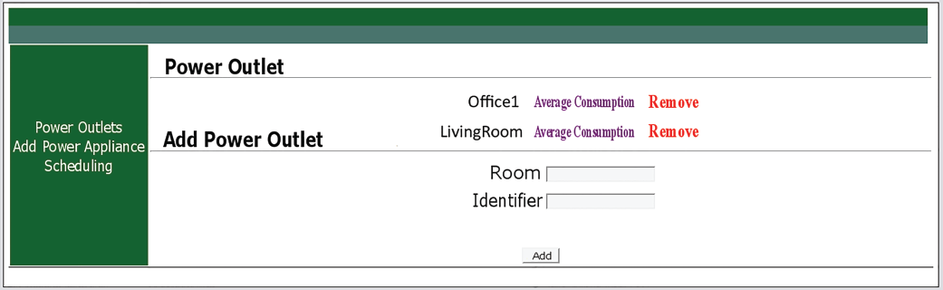
Example of the screen for enumerating and adding new power sockets to the system.
5.2. Implemented Features
The testbed developed currently monitors the following events:
If an appliance with a valid RFID tag is plugged into the smart power outlet, the power supply is enabled. Note that RFID tag is always associated with the same appliance (it would be ideally attached by the manufacturer), but every valid appliance is authorized by default to be used in every smart power outlet of the system. If the current exceeds the maximum allowed during If the maximum current slope is exceeded, an overcurrent is detected and the relay opens the circuit. Note that the slope can be adjusted to the environment to get a trade-off between detections and false positives. A commercial implementation would require testing the system in real-world situations and adjusting accurately the rate of false positives. If the inner workings of an appliance would result in sudden rises of current, its power profile should be configured properly to filter them out. If the current remains below the recommended minimum during at least the vampire current detection time indicated in the power profile, a vampire current is detected and the system stops supplying current. If there is a powering schedule for the power outlet setup, the appliance will be powered off during the time intervals indicated by such a schedule. Remote user management commands are the sixth item. Users can list and add new power outlets to the system. If a remote user carries out certain action (e.g., switching on/off an outlet or viewing the historical current consumption), it will be executed if there are no other more critical tasks running.
Other functionalities that are not currently implemented but that would be straightforward to implement on the testbed are as follows:
Power load balance mode. The intelligent sockets can exchange information to avoid overloads or to respect a maximum power limit imposed by the user. Appliance fail pattern. By monitoring current it is possible to detect when a device is malfunctioning and predict when it is going to fail [43]. Smart powering. The system can embed sensors that determine the value of parameters like temperature, humidity, or presence that might lead to an intelligent powering of the connected appliances. For instance, it may not make sense to activate a heating system when a room is hot enough or when it has not detected the presence of people in the environment for certain amount of time. Cost-efficient powering. In some European countries the cost of residential electricity oscillates throughout the day. The system may be adapted to obtain the prices from the Internet and only power certain appliances when the electricity cost is below a value previously set.
5.3. Cost of the System
The components of the testbed can be manufactured currently for 45€ (the smart power outlet) and 20€ (the gateway, without the PC), when buying in bulk 10,000 units. The most expensive component is the ZigBee module (around 15€ in bulk), which can be replaced by other RF interfaces with mesh capabilities (e.g., ESP8266), which would make the cost of both devices go down to 32€ and 7€, respectively.
It is worth also noting that the cost can also be reduced by not using certain subsystems. For instance, if the identification subsystem is removed (its functionalities would be carried out partially by the user, who would be responsible for associating every outlet with an appliance), the manufacturing cost of the smart power outlet in bulk would be around 25€.
On the contrary, the system could be enhanced by replacing some of the components with more accurate ones at the expense of increasing the cost of the system. For example, more expensive current sensors would allow for obtaining more precise measurements and, thus, fine-tune vampire current and overcurrent detection. The actuation subsystem could also be improved by incorporating relays that feature higher maximum currents, reduced switching time, and more durability, but the cost of the smart power outlet would be increased significantly.
6. Experimental Analysis
6.1. Signal Attenuation
One of the problems of indoor wireless communications is that signals are reflected, refracted, absorbed and, therefore, attenuated by the multiple obstacles present in the environment. In order to test the communications architecture, the testbed was placed in an indoor environment and the attenuation of the signals was measured. Specifically, the mean RSSI (Received Signal Strength Indicator) value obtained during the reception of 100 messages sent from a smart socket to the gateway was measured. Each measure was averaged five times for each measurement to counteract the signal fluctuations caused by indoor fading. Both the gateway and the smart socket transmitted with a power of 3 dBm and boost mode was enabled. The results obtained show that, as it was expected, the signal attenuates with the distance (e.g., the signal mean attenuation with line-of-sight at 2 m was 12.05 dB, while at 8 m it was 22.99 dB) and depending on the material of the obstacles the signal encounters (e.g., the mean attenuation at 50 cm for a brick wall was 1.46 dB, but it was 3.95 dB for a window with closed metallic blinds). Such results highlight the need for a WSN-based communications architecture, whose use of certain nodes as repeaters allows for compensating signal attenuations.
6.2. Current Monitoring
It is possible to monitor remotely the state of the network of smart sockets. The management system offers the possibility of monitoring the current consumption in real-time and obtain the historical consumption during a specific time interval.
Figure 8 shows an example of the current consumed by a hairdryer. Such a figure was obtained when the hairdryer was turned on and then switched between the different numbers that are associated with power levels (it can be observed that there are four different consumption levels).

Current oscillation when monitoring a hairdryer.
6.3. Electrical Event Reaction and Detection Times
A key feature of the system is the possibility of stopping the current from flowing when detecting an abnormal electrical behavior before electrical fire or damage occurs in the cases when the circuit breaker does not open the circuit fast enough.
In order to determine the detection time of an electrical event, theoretical and empirical analysis were performed. In both cases the detection time is modeled as exposed in (7), (8), and (9). Note that, as it was previously mentioned, there are times that are exclusively dependent on the hardware (
6.3.1. Hardware Detection Times
The time
In the case of
6.3.2. Theoretical Software Detection Times
The time required by the ATmega328P to execute the code can be estimated before its execution by counting the number of cycles it requires. To estimate such a number it is necessary to count, for each type of instruction, the number of assembler instructions required by the code and then multiply it by the number of cycles per instruction and by the period of the system (the inverse of the microcontroller clock frequency):
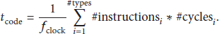
In the case of the ATmega328P, it runs at 16 MHz. According to its datasheet there are no dividers for the external clock signal; therefore the period is 62.5 nS.
The counting of the assembler instructions is a tedious task since it requires following the right branch of every jump in the code (that is not always obvious) and counting the cycles consumed by every executed instruction (indicated in the microcontroller's datasheet). As an example, Table 1 shows the instruction count for some of the most common instructions of the executed code (the first row of Table 1 indicates the number of clock cycles consumed by each of the instructions). Table 2 contains the total number of cycles required by each segment of code and shows the total theoretical time of
Count of the most common instructions executed in different segments of code.

Theoretical and empirical reaction times.

It is important to note that
6.3.3. Empirical Software Detection Times
With the objective of verifying the empirical detection times, the real execution time of the different parts of the code was quantified by using functions that rely on the timers of the microcontroller. Table 2 shows on the right the empirical times when averaging 10,000 times the measurement for each section of the code.
Note that the main loop section requires roughly 111.6 μs, in contrast to the theoretical time, which only requires 29.4 μs. This difference is due to the fact that it also includes the time required to handle certain asynchronous interruptions and verifications, which were not computed when counting instructions during the theoretical analysis.
There is only one software function that carries out the task of acquiring the current sensor data and that determines whether the relay has to be opened. An average of 117.6 μs elapsed when executing such a function, which is really similar to the sum of the theoretical values of
6.3.4. Reaction Time Comparison
After all the theoretical and empirical measurements it can be observed that both approximations yield similar values (with a difference of 75 μs) and that the software side of the system does not constitute a bottleneck: even in the worst case (empirical measurements) it would be clearly less than the average circuit breaker trip time (20 ms). It can be also concluded that the time required by the relay to open the circuit is critical and restricts the ability of the system to react faster to electrical events.
7. Conclusions
This paper has presented the design and implementation of a ZigBee-based smart power socket system whose functionalities include remote control, current consumption monitoring, avoidance of overconsumptions, detection of vampire currents, and the prevention of electrical fires and shocks. In order to demonstrate such features, a simple testbed was set up and several experiments were performed. The results obtained confirm the feasibility of the system and, after analyzing the results, it can be stated that it provides a fast and flexible alternative to make future homes smarter and safer.
Footnotes
Conflict of Interests
The author declares that there is no conflict of interests regarding the publication of this paper.
Acknowledgments
This work has been funded by Xunta de Galicia, Ministerio de Economía y Competitividad of Spain, and FEDER funds of the European Union under Grants 2012/287, R2014/037, and TEC2013-47141-C4-1-R. The author would like to thank Rafael Constenla Casal for his assistance during the whole development of the system.