
Abstract
For large structural health monitoring in practical applications, the sensor failure in large sensor network will generate the failure of the damage evaluation or the leaving of unmonitored area in a large structure. Hence, in order to realize a real-time and reliable evaluation for the large structural damage and satisfy the requirement of advanced maintenance of the structure, the paper introduces an efficient piezoelectric sensor failure monitoring approach integrated with self-diagnosis and self-reconfiguration reasoning method. Firstly, the developed method is introduced for large structural health monitoring. Then, the effects of piezoelectric actuator and sensor bonding defects on Lamb wave propagations are investigated in a real-world monitoring experiment for the large aviation aluminum plate. Lastly, the self-diagnosis and self-reconfiguration method of piezoelectric actuator and sensor network for large structural health monitoring based on Lamb wave for the passive and active damage monitoring is verified in the experiment. Based on the results shown in the experiment, a big potential in real-time application demonstrates that the method can accurately and rapidly identify the sensor failure by reasoning and analyzing Lamb wave propagations using proposed methods.
1. Introduction
Structural health monitoring (SHM) based on the use of Lamb wave propagations requires relatively a large number of piezoelectric active sensors. These transducers can be installed either individually or collectively, such as smart layer networks, or the sensors (such as PVDF) can cover the entire surface of the structure. If one sensor inside the network fails, it creates major problems including the failure of the signal processing algorithms or, as a minimum, leaving a large area of a structure unmonitored. The faulty sensors can come from an extreme operational condition, such as an impact. However, sensor failure can also come from the improper installation of the sensors, including imperfect bonding or accidental sensor breakage during handling.
The problem of sensor self-diagnosis and self-reconfiguration in SHM has been studied by different researchers. The principle in these techniques consists of two parts. Some researchers concentrate on the study of acceleration sensor measuring the low frequency response, and others mainly study the piezoelectric (PZT) sensor.
For acceleration sensor, Friswell and Inman (1999) use the modal filtering approaches to generate the residuals between the output of the response and the model for detecting and isolating a faulty sensor in a sensing network [1]. Worden (2003) examines the autoassociative neural network and the principal component analysis (PCA) for the detection of sensor failures [2]. Kerschen et al. (2005) present and utilize PCA to detect, isolate, and reconstruct the faulty sensor.
In self-diagnosis research of piezoelectric sensor, the researchers are to seek out the changes in the sensor static properties as indicators of sensor fault in the structure [3]. Saint-Pierre et al. (1996), Giurgiutiu and Zagrai (2002), and Pacou et al. (2002) identify the debonding by monitoring the resonance of a PZT sensor measured by electrical impedances [4–6]. Bhalla and Soh (2004) find that the imaginary part of the electrical admittance of PZT sensor may play a meaningful role in detecting the bonding of sensor [7]. Park (2006, 2009, and 2013) employs the capacitive of PZT sensor to identify the degradation of its mechanical/electrical properties and bonding [8–10]. It is also utilized to distinguish response changes caused by sensor failure and structural damage. For the above researches, the sensor self-reconfiguration is less studied.
However, for practical applications, the piezoelectric actuator and sensor network is required to introduce the self-diagnosis and reconfiguration of the piezoelectric ones in order to prove the fast and efficient damage evaluation in a large structure. Therefore, for large SHM, an efficient method is introduced to self-diagnose and self-reconfigure piezoelectric actuator and sensor network and give the more reliable evaluation for the large structural damage.
The paper introduces an efficient PZT sensor failure monitoring approach integrated with self-diagnosis and reconfiguration reasoning method. Firstly, a developed self-diagnosis and configuration method is presented for large SHM. Then, the effects of PZT actuator and sensor bonding defects on Lamb wave propagations are investigated in a real-world monitoring experiment for the large aviation aluminum plate. Lastly, the self-diagnosis and self-reconfiguration method of PZT actuator and sensor network for the passive and active damage monitoring is verified in the experiment. Based on the results shown in the experiment, a big potential in real-time application demonstrates that the method can accurately and rapidly identify the sensor failure by reasoning and analyzing Lamb wave propagations using proposed methods.
The rest of this paper is structured in the following manner. In Section 2, the self-diagnosis and self-reconfiguration reasoning method is introduced for large SHM. Section 3 gives experimental validation, results, and discussion for large aviation aluminum plate structure. Finally, Section 4 concludes the paper.
2. Self-Diagnosis and Self-Reconfiguration Sensor Network for Large Structural Health Monitoring
This section introduces the self-diagnosis and configuration sensor network for large SHM, which is based on Beard's method [11], and some improvement and complement which we made. The flow chart of the self-diagnosis and self-reconfiguration sensor network for large SHM is given in Figure 1. Abnormal signal of piezoelectric element generates from the temperature change, structure damage, and sensor failure.
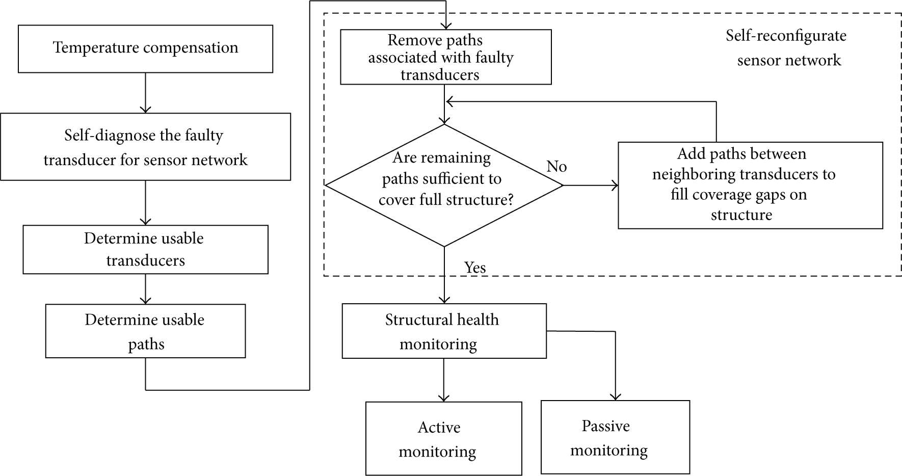
The principle of the self-diagnosis and self-reconfiguration sensor network for large SHM.
Firstly, by instantaneously acquiring a baseline measurement on a structure, based on the temperature sensor's measurement, the prerecorded baseline is compensated. With the temperature compensation, we can eliminate the effects of temperature variation on the sensor diagnostic process. Then, the difference between the measurement and the compensated baseline is adopted, and the signal variation is generated by the structure damage or PZT sensor failure. Hence, a sensor self-diagnostic process based on the active Lamb method is performed. This reasoning process involves comparing signals on paths going directly through a suspect PZT transducer to signals obtained from prior baseline measurements. Based on the failure PZT transducer diagnosed, the self-reconfiguration is performed to cover the gap region generated by the removing of the faulty sensor. At last, the active and passive SHM are introduced to monitor the entire structural damage.
2.1. Self-Diagnosis Sensor Network for Large SHM
In the sensor self-diagnosis method, the active Lamb method based on PZT transducer is adopted to excite and sense the Lamb elastic wave signal on the structure between pairs of tranducers. Below PZT transducer's complete and partial failures are discussed, respectively; for instance, partial disbond from the structure is one example of degradation.
A detailed reasoning process may be used to self-diagnose degraded PZT transducer as follows. If there are signal differences between the obtained and baseline data for all actuator-sensor paths associated with a given PZT transducer, but there are no substantial signal changes on paths going directly through a particular transducer in question to a third transducer directly in line with the first two, then this is an indication of a degraded transducer. Such a transducer would therefore be incapable of detecting or exciting an elastic wave signal on the structure, or only weakly capable of doing so.
For example, referring to Figure 2, paths between all adjacent vertical, horizontal, or diagonal PZT transducers are indicated by solid double arrow. If Paths 1-2 and 2-3 between PZT transducers (PZT) 1 and 2 and between 2 and 3 show signal changes, including either a weakened signal or loss of signal, but Path 1-3 between PZT 1 and 3 does not show any change relative to baseline data records, then this may indicate that PZT 2 may be partially damaged or completely disbonded. Similarly, if Path 1-2 shows no change, but 1-3 and 2-3 show changes, then this indicates that PZT 3 is suspected of degradation. Because the configuration is symmetric about PZT 2, 1 may be similarly diagnosed.

The actuator-sensor scheme of sensor self-diagnosis.
Alternative combinations, in which the path direction is reversed, may be considered, and reciprocity predicts that the observed results will be the same. Thus, if the sensor network has at least three transducers arranged in line with each other, and one of the transducers may be defective, it can be identified whether it is an interior transducer of network or an edge transducer of network. However, three signals are all weak. It is known that there is the faulty transducer in the three elements, but more than two in them are failure. Hence, the other three neighbouring PZT transducers in line are employed to reason the final result in the subregion. Then, by the above introduced self-diagnosis process for three sensors in line, the reasoning for Paths 1-2-3, 1-4-7, 1-5-6, 4-5-6, 3-5-7, 3-6-9, and 7-8-9 is finished. Hence, the failure condition of the nine sensors is obtained [11].
For the partial disbond of PZT transducer, the failure factor is presented to measure the sensor failure degree. Assuming that, for some actuator-sensor path, the acquired signal of the healthy sensor is

Once the factor is among the threshold (solved by experiment) and 1, it is deemed that the actuator or sensor is healthy or faulty. Then, the above reasoning process is used to estimate the health condition of all the sensors in the subarea.
2.2. Self-Reconfiguration Sensor Network for Large SHM
Given this ability to detect failure PZT transducers, which may impact the capacity of a network with a designated set of actuator-sensor paths to monitor structural damage of a given minimum size, the next step in self-diagnosis involves strategies for self-reconfiguration network to retain the full coverage of the structure. Self-reconfiguration is an adaptive process, for example, of adding new actuator-sensor paths between different pairs of PZT transducers compared to those previously selected in order to cover the same area as previously provided, or to guarantee that the new paths provide coverage that enables monitoring of damage having greater than a specified minimum size within the network area.
Coverage may be considered sufficient, for example, when paths can be generated to monitor damage equal to or greater than a selected size. Thus, when new paths are generated to satisfy coverage sufficiency, whether any defect of at least a selected size may be considered monitorable with the new set of paths only if it always intersects at least one actuator-sensor when located anywhere within the PZT transducer network. Other criteria defining coverage may be selected, the above description being only exemplary and not intended to be limiting. For example, selected criteria may be dependent on the length of the new path as well as on the amplitude and/or time-of-arrival of pulse signal.
Figure 3 illustrates, as an exemplary case, how new-path generation can be implemented to maintain coverage in a 3
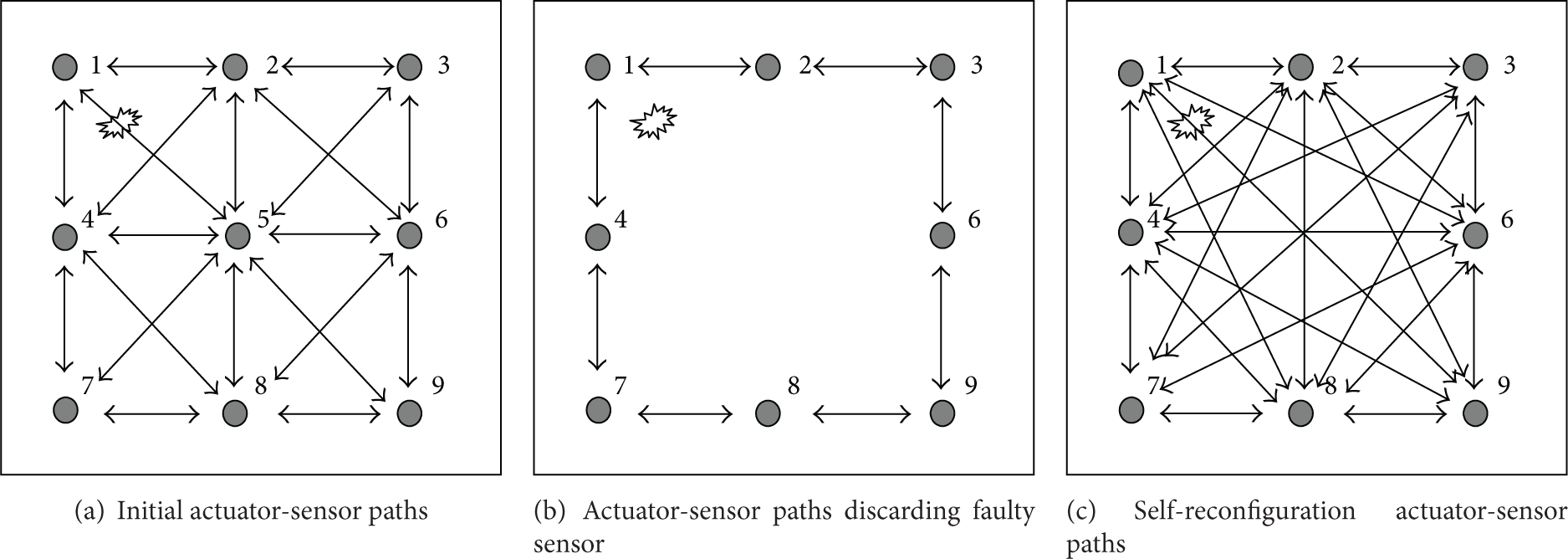
Active damage monitoring self-reconfiguration network 1 after PZT 5 is faulty.
Figure 3(b) represents network when center PZT 5 of network is found, as a result of self-diagnosis method, missing, disbonded, or otherwise inoperative for SHM. Using the self-reconfiguration method, all paths associated with defective (or missing) center PZT 5 are removed. Damage now occupies a region of the structure not covered by any of the remaining actuator-sensor paths specified in the original configuration. Since coverage is now insufficient to monitor a damage of at least the specified size, paths between other PZT transducer pairs may be added or extended to pass through the location of the missing PZT 5 or otherwise guarantee that damage will be intersected by a path between two remaining PZT transducers.
Figure 3(c) represents network with new paths added: diagonal paths between PZT transducers at opposite corners and horizontal and vertical paths between PZT transducers at the mid-points of the edges of network. Thus, in effect, all actuator-sensor trajectories are recovered, and damage now lies in at least one of the added paths and may be monitored. Accordingly, the SHM system may continue to verify sensor network self-diagnosis with actuator-sensor method along the selected paths to determine if the PZT transducer defects not found in self-diagnosis method still exist. When the predicted coverage is then obtained, the damage active monitoring may be performed.
Figure 4 illustrates an example of loss of more PZT transducers at the edge of the network in case of faulty PZT 5, where the benefit of simply extending a path is not available. Figure 4(a) is substantially identical to Figure 3(a). Damage is located in substantially the same place and is of substantially the same size as that damage. In Figure 4, the loss of PZT 4 and 5 results in the removal of a number of paths, in which damage is not able to be covered. Method may then add a new “alternate” diagonal path that may intersect damage located at the same position.

Active damage monitoring self-reconfiguration network 2 after PZT 4 and 5 are faulty.
The above self-reconfiguration network is based on the active damage monitoring [11]. Figure 5 illustrates an example of the one for passive impact monitoring. The impact or acoustic emission source is located in the upper left of PZT 5. If PZT 5 fails, it results in the removal of three paths related with the transducer. Then, the new network is organized to monitor the source continually as shown in Figure 5.
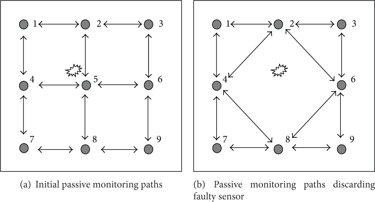
Passive impact monitoring self-reconfiguration network after PZT 5 is faulty.
3. Experiment Validation, Results, and Discussion
The experiment structure, shown in Figure 6, is an aluminum plate (1200 mm × 1200 mm × 2 mm). Nine circular PZT patches are mounted using superglue on one surface with a 3 × 3 array of the equal distance. The locations and the numbering schemes of these actuators/sensors are shown in Figure 6(b). The size of the circular PZT patch is 5.5 mm diameter with 0.2 mm thickness. The active and passive monitoring are finished by the multichannel piezoelectric scanning system [12], which integrates waveform generator module, data acquisition module, charge amplifier module, digital I/O module, multichannel scanning switch board, and power amplifier.

Aluminum plate and sensor setup.
3.1. The Effects of Piezoelectric Actuator and Sensor Bonding Defects on LAMB Wave Propagations
The effect of bonding defects on the Lamb wave propagation between faulty or healthy actuator and faulty or healthy sensor is investigated in order to prove the self-diagnosis and self-reconfiguration method as follows. Our experiment is based on the one finished by Park et al. [8], and we obtain the same conclusion. Here, the Lamb wave propagation between healthy actuator and healthy sensor is as the baseline.
As shown in Figure 7, PZT 1, 4, and 5 are faulty, and the other six sensors are healthy. The five-peak wave signal of ±7 V amplitude and 100 kHz frequency is excited by the PZT actuator to the structure for generating the Lamb wave of the

Lamb wave propagation I between faulty actuator and healthy sensor.
Firstly, the effect of bonding defects on the Lamb wave propagation between faulty actuator and healthy sensor is investigated in Figures 7 and 8. The wave propagation in the path between sensors with the good bonding condition shows the approximately same magnitude and phase. However, comparing the wave propagation in the path between faulty actuator and healthy sensor with the one between healthy transducers, there is a remarkable change in the magnitude, and, further, the change in the arrival time can also be clearly observed. It is speculated that, with the bonding defects, there might be a delay in PZT excitation and phase distortion, or the PZT actuator may not be able to efficiently excite the input frequency [8].

Lamb wave propagation II between faulty actuator and healthy sensor.
Secondly, the effect of ones between healthy actuator and faulty sensor is investigated as shown in Figure 9. The same phenomena can be observed and similar conclusions can be drawn from the above paragraph.

Lamb wave propagation between healthy actuator and faulty sensor.
At last, the effect of bonding defects on the Lamb wave propagation between faulty actuator and faulty sensor is investigated. As can be seen in Figures 10 and 11, the bonding defects cause the significant distortion in the shape of the propagated wave, rather than merely causing the decrease in the magnitude and the change of the arrival time. The reason is that the faulty bonding condition would make the excitation of PZT actuator no longer linear and multiple excitations from a single piezoelectric source [8].

Lamb wave propagation between healthy actuator and healthy sensor.

Lamb wave propagation between faulty actuator and faulty sensor.
If the damage evaluation methods based on the wave amplitude or the arrival time information are to be used, and the bonding defect occurs during the SHM operation, these changes can be mistakenly considered as structural damage, which points out the importance of the sensor diagnostics in the real application.
3.2. Self-Diagnosis of Piezoelectric Actuator and Sensor Network
In this section, the proposed sensor diagnostic process in Section 2 is used to determine the operational status of the sensing network right after the installation for the aluminum plate. Eight PZT transducer paths in line in sensing network are adopted to reason two faulty, one faulty, or all the healthy ones in any three ones in line.
To analyze the signal change caused by the PZT transducer bonding, the five-peak wave signal with ±7 V amplitude and 50 kHz frequency is adopted to excite the structure and generate the Lamb wave of the single
The sensor signal between healthy actuator and sensor.

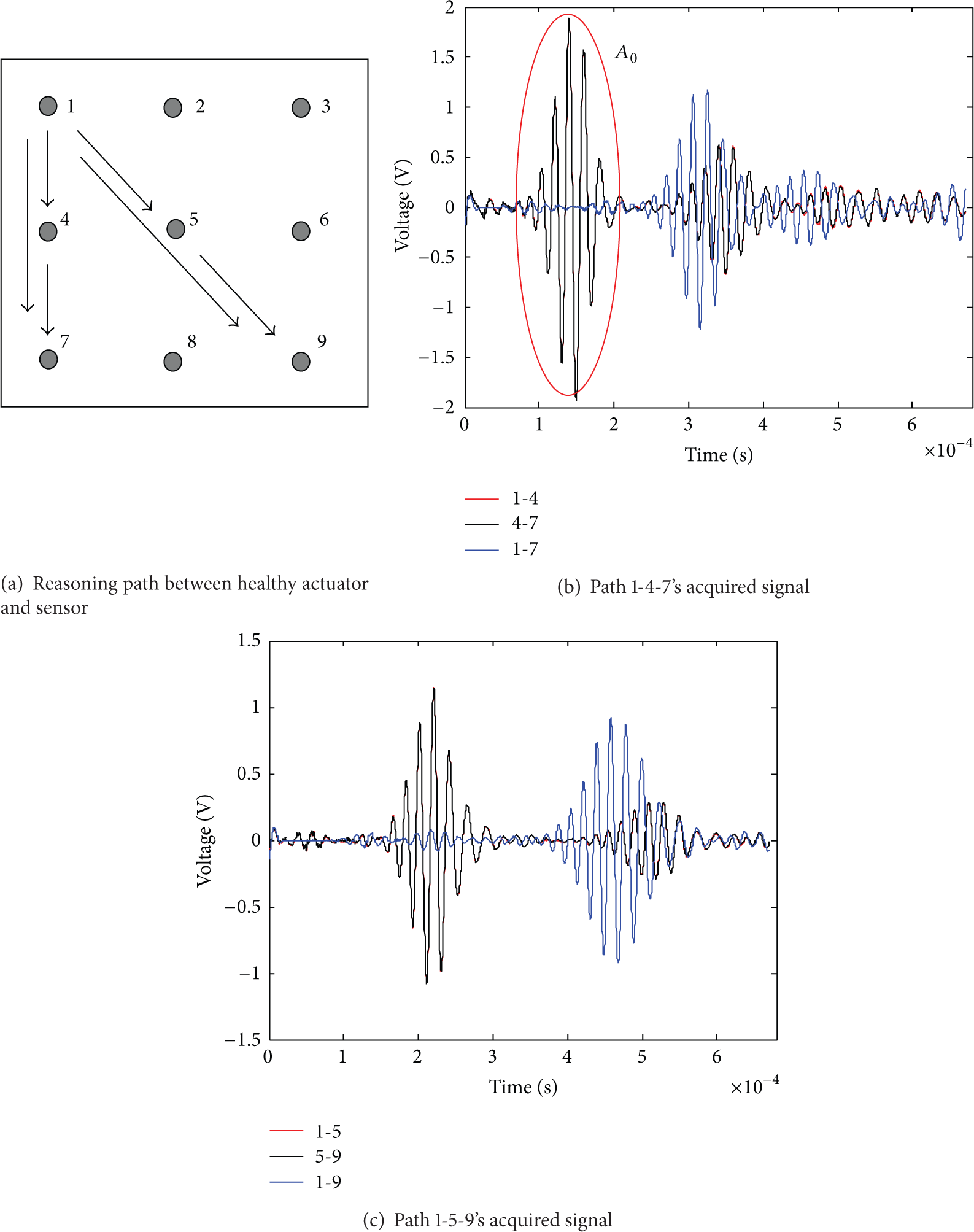
The self-diagnosis reasoning path and acquired signal between faulty actuator and sensor.
In another experimental result, the effects of faulty sensors in Path 1-5-9 are very similar to those above as shown in Figure 13. For Path 1-2-3, the measured magnitude of PZT 2 and 3 as healthy sensor caused by PZT 1 as faulty actuator clearly changes in Figure 14. As shown in Figure 15, for Paths 2-5-8 and 3-5-7, the faulty PZT 5 remarkably affects the measurement response of Path 2-5, 5-8 or 3-5, 5-7. Regardless of PZT 5 as actuator or sensor, the same phenomena can be observed and similar conclusions can be drawn from the figure. In Figure 16, for the healthy Paths 3-6-9 and 9-8-7, the related response is similar to those in the healthy Path 1-4-7. Therefore, these sensors are identified by the sensor diagnostic method.

The self-diagnosis reasoning path and acquired signal between faulty actuator and healthy sensor.

The self-diagnosis reasoning path and acquired signal between healthy actuator and faulty sensor.
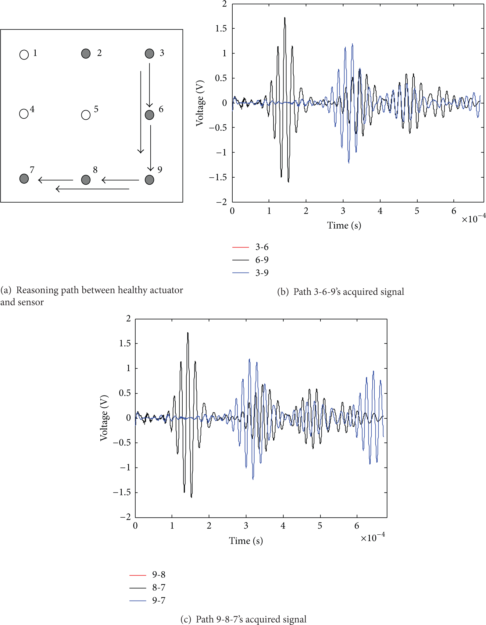
The self-diagnosis reasoning path and acquired signal between healthy actuator and sensor.
The signals of healthy or faulty PZT 1, 4, and 5 are shown in Figures 12 and 13. The failure factor of each reasoning path is obtained with its faulty signal and healthy one, as shown in Table 1. The previous 1500 dot data of the sensor signal is cut out to obtain the direct
The signal failure factor in the reasoning path for faulty or healthy transducer.

As can be seen in Table 1, the reasoning result in Paths 1-2-3, 2-5-8, and 3-5-7 indicates that PZT 1 and 5 are faulty and PZT 2, 3, 7, and 8 are healthy. With the reasoning result in Paths 3-6-9 and 9-8-7, it is confirmed that PZT 6 and 9 are healthy. Meanwhile, the faulty PZT 4 is reasoned and known with Paths 1-4-7 and 1-5-9. Above all, in the nine transducers, except PZT 1, 4, and 5 being faulty, other transducers are healthy. Hence, the proposed sensor diagnostic method is efficient in monitoring the operational status of the PZT transducers right after their installation.
3.3. Self-Reconfiguration of Piezoelectric Actuator and Sensor Network
3.3.1. Damage Location Self-Reconfiguration of Active Piezoelectric Network
In the above section, the SHM system is firstly in charge of monitoring the state of PZT transducers on the aluminum plate, and it is found that PZT 1, 4, and 5 are partly disbonded. Then the monitoring system will self-organize the actuator-sensor path of the PZT transducer network to cover the damage and adopt the damage factor algorithm [13] to evaluate the damage location. To verify the effectiveness of the presented method, the damage is simulated by mass block with 50 g weight loading the structure, and the ones on positions 6, 7, and 11 are considered in Figure 17. A five-peak wave signal of ±7 V amplitude and 50 kHz frequency is excited by the PZT actuator to the structure. The coordinate systems used for the damage location are as shown in Figure 17.

Damage position.
Figure 18 gives the original actuator-sensor network when all PZT transducers are healthy and PZT 1, 4, and 5 are of failure and the self-reconfiguration network when PZT 1, 4, and 5 are of failure.
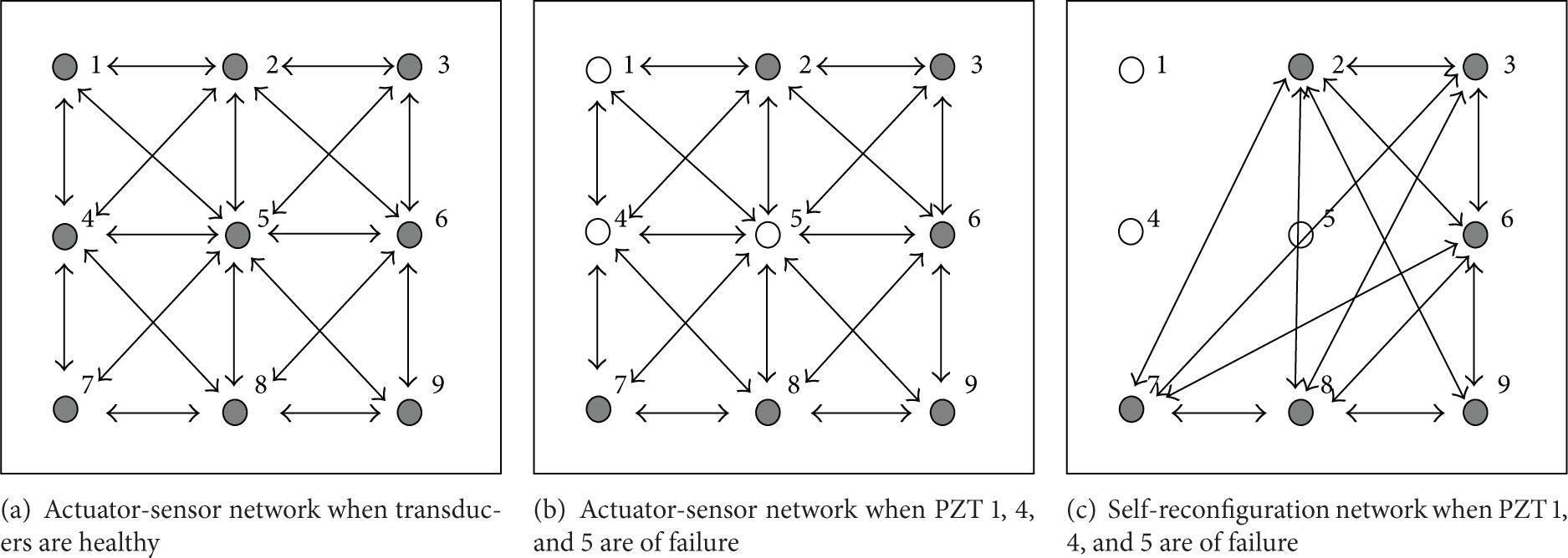
Actuator-sensor network when transducers are healthy or not.
The computation results for three damage positions when the PZT transducers are healthy are given as follows. The adopted actuator-sensor network is as shown in Figure 18(a). The location results for damage positions 6, 7, and 11 are (−13.7 cm, 8.8 cm), (8.2 cm, 10.1 cm), and (11.5 cm, −9.7 cm). Their errors are 3.9 cm, 1.9 cm, and 1.5 cm, which is defined as the Euclide distance from the actual damage location to the calculated location. However, the calculated error of position 6 is far large, and the corresponding location error of positions 7 and 11 is less than 4.0 cm. From these results, it can be found that when the damage location is near the subregion boundary, the identification accuracy of the damage position decreases, and in the subregion there is good agreement between the actual and calculated location. The reason of the positioning inaccuracy on the border is that the damage is not easily covered sufficiently by actuator-sensor path.
The computation results for three damage positions when PZT 1, 4, and 5 are of failure are given as follows. When the actuator-sensor network in Figure 18(b) is adopted, the location results for damage positions 6, 7, and 11 are (−18.2 cm, 8.9 cm), (1.1 cm, 1.3 cm), and (5.6 cm, −5.7 cm). Their errors are 8.4 cm, 12.4 cm, and 6.1 cm. It is well known that the calculated errors of three positions are far large and near 10.0 cm. When the self-reconfiguration actuator-sensor network in Figure 18(c) is adopted, the location results for damage positions 6, 7, and 11 are (−4.0 cm, 12.5 cm), (9.0 cm, 8.9 cm), and (7.9 cm, −7.3 cm). Their errors are 6.6 cm, 1.6 cm, and 3.5 cm. It is shown that the errors for the self-reconfiguration actuator-sensor network are less than no self-reconfiguration. The reason is mainly from the signal change of sensor failure. Since the self-reconfiguration network cannot fully cover the damage, its damage location error is more than the one of the healthy network.
3.3.2. Acoustic Emission Location Self-Reconfiguration of Passive Piezoelectric Network
As above, the faulty PZT 1, 4, and 5 on the aluminum plate are identified with the self-diagnosis method of the SHM system. Then, the monitoring system will discard the faulty sensor and adopt the healthy sensor to locate the acoustic emission source with the triangulation method [14], whose sensor network is as shown in Figure 19(a). To verify the effectiveness of the presented method, the acoustic emission damage is simulated by the pencil lead break on the plate, and the ones on twelve positions are considered in Figure 17.

Acoustic emission location result for passive sensor network when transducers are faulty and healthy.
Figure 19(b) gives the identification results. The actual acoustic emission location is represented by “
Therefore, after the sensor network's self-diagnosis is finished, the active monitoring needs to discard the faulty sensor and self-organize the transducer network to cover the damage. However, the passive monitoring needs to consider the sensor failure level. For fully faulty of the sensor, the system is needed to self-organize the sensor network. For partial failure of one, the faulty sensor is still utilized to evaluate the damage.
4. Conclusions
In order to realize a real-time and reliable evaluation for the large structural damage and satisfy the requirement of advanced maintenance of the structure, the paper proposes an efficient piezoelectric sensor failure monitoring approach integrated with self-diagnosis and reconfiguration reasoning method. Based on the results shown in the experiment, a big potential in real-time application for the passive and active damage monitoring is presented in which the method can accurately and rapidly identify the sensor failure by reasoning and analyzing Lamb wave propagations using proposed methods.
Based on the piezoelectric sensor failure monitoring framework, further studies are required concentrating on the following three parts:
Further studying of PZT transducer self-diagnostic reasoning method: when the damage and sensor failure occur simultaneously, the sensor failure is still effectively identified. The precision between the self-reconfigurable topology network problems and different damage location is considered in depth. The sensor self-diagnosis on the disbonded extent of the PZT transducer and fracture, measuring circuit failure modes, is required to be considered.
Footnotes
Conflict of Interests
The authors do not have a conflict of interests in this paper.
Acknowledgments
This work is supported by the National Natural Science Foundation of China (Grant no. 51405409) and the Fundamental Research Funds for the Central Universities.