
Abstract
The following paper describes architecture of the Wireless Vehicle Weight Measurement System (WVWMS). The challenge was to design a road scale system enabling multipoint vehicle weight with the single network sink. The proposed platform is capable of weight measurement based on electrical strain gauge weight pads and in-node data processing. Communication is wireless, with mesh networking. The developed vehicle weight measurement is one of subsystems applied in the TULCOEMPA project. It is required to cooperate with Structural Health Monitoring and Truck Recognition Systems. Due to the absence of mains line, all installations are powered by Hybrid Power System. The authors propose Energy Harvesting Controller cooperating with both solar panels and wind generators. The controller enables efficient energy harvesting from both power sources as well as monitoring of generated and consumed power levels. Next challenge was a design of vehicle weight data acquisition software architecture. The solution includes application of modern architectural concepts in software design, Representational State Transfer (REST), Model-View-View Model (MVVM) paradigm, and cloud computing. Communication between vehicle weight measurement modules and server application is described.
1. Introduction
Wireless Sensor Networks are widely applied in structural health monitoring solutions [1]. Measurement data, for example, strain of concrete bridge, provide valuable feedback for civil engineers [2, 3]. Acquisition of different types of data and their correlation leads to a more thorough diagnosis of a monitored object. Wireless communication enables usage of such systems in places, where structural cabling is not advisable, for instance, in heritage buildings [4] or due to formal restrictions. Additionally, deployment time and cost are reduced. Location of measurement points can be easily changed.
The aim of the described project is a design of scalable, multipoint vehicle weight measurement system with wireless communication, short response time, and in-node processing. To achieve this goal, wireless mesh networking was applied. IPv6 connectivity simplifies integration with backbone network and remote data acquisition system.
The WVWMS cooperates with other subsystems, which are the part of TULCOEMPA project. Therefore, the following section describes them and the project objectives.
TULCOEMPA Project Description. The TULCOEMPA project is based on the Swiss-Polish cooperation between the Lodz University of Technology and Swiss Material Science Institute EMPA. From the Lodz University of Technology two departments are involved: DMCS (Department of Microelectronics and Computer Science) and KBB (Concrete Construction Department). Multipurpose program of the project covers civil engineering and structural health monitoring of buildings. Unanchored prestressed carbon fibre reinforced polymer laminates will be used for bridge strengthening. A bridge located in Szczercowska Wieś, central part of Poland, is used as a model one. To ensure effectiveness of this innovative solution, a long-term monitoring of the structure will be applied [5]. It will include multipoint measuring system composed of wireless sensors, sink base station, and computer system for collecting, processing, and data coding. Strain will be measured with low frequency and, additionally, with high frequency for short periods of time. This enables the behaviour assessment of the bridge during heavy loadings. Dynamic measurements will occur only when presence of a heavy vehicle is detected by TRS (Truck Recognition System). It will reduce WSS (Wireless Strain Sensor) devices power consumption. The Truck Recognition System is described below.
Results from structural health monitoring installation are required to correlate with weights of passing vehicles. A level of concrete lamellae strain paired with weight of a vehicle passing through the bridge provides valuable information about efficiency of lamella reinforcement solution. Furthermore, measurement results are required for verification of the simulation model of the bridge. What is more, vehicle weight data can be used to asses TRS effectiveness, and when needed, to support it. On the other hand, when TRS shows high accuracy, it can be used to activate weight measurement. Avoidance of continuous weight measurement can significantly increase node battery life. Due to mains power supply unavailability, all subsystems are powered by the Hybrid Power System. As a result, low energy consumption is necessary. To meet the described requirements, the authors propose the Wireless Vehicle Weight Measurement System, described in Section 2.
All subsystems are deployed on the bridge as shown in Figure 1 and relation between them in Figure 2.
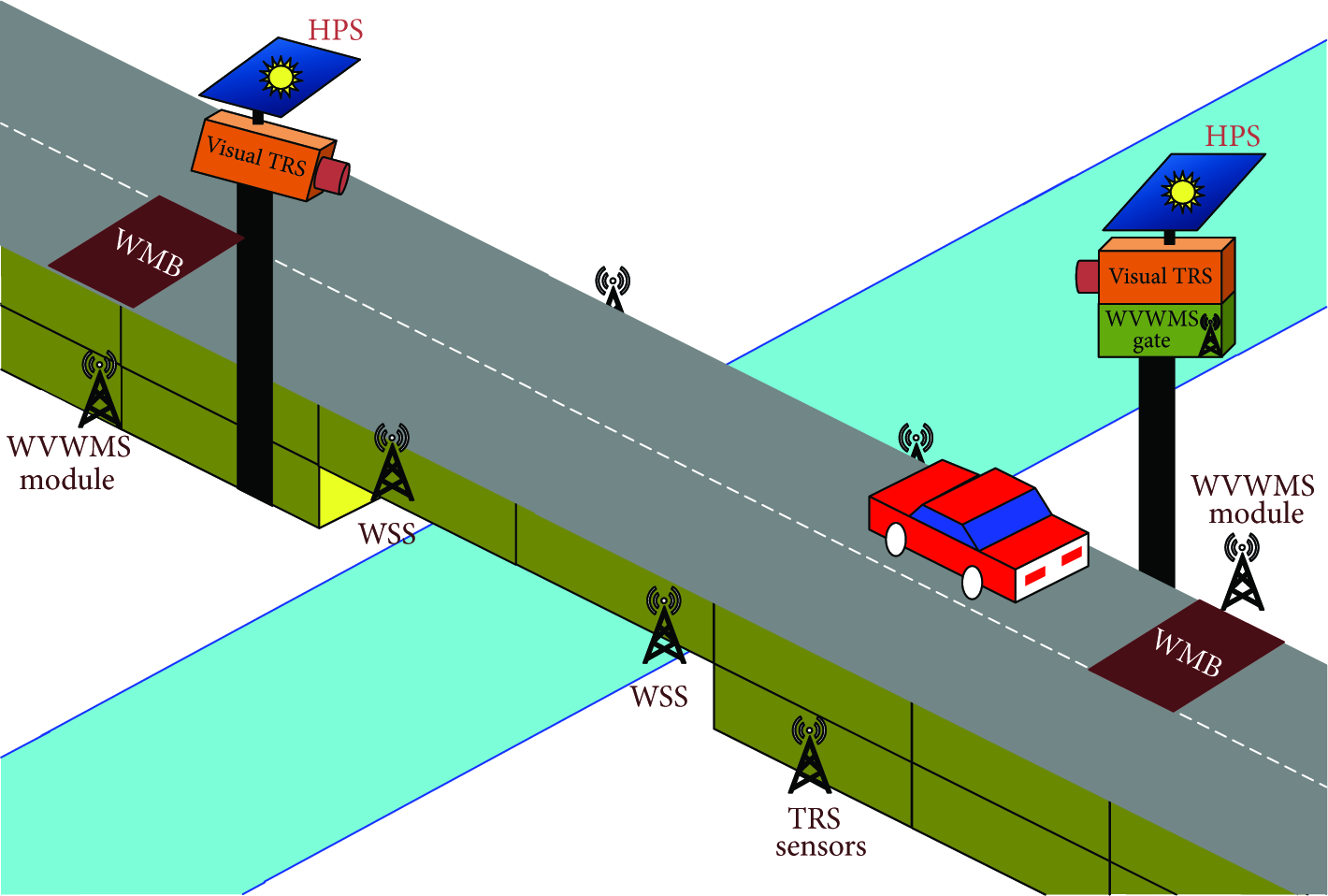
TULCOEMPA subsystems deployed on the bridge: Wireless Strain Sensors, Truck Recognition System, and Wireless Vehicle Weight Measurement System.

TULCOEMPA subsystems dependencies.
Truck Recognition System Overview. One of the main tasks in the TULCOEMPA project is a development of the Truck Recognition System. As described in the introduction, its aim is the detection of the trucks passing through the bridge. This event is sent to the Health Monitoring System in order to trigger high-frequency strain measurement. Vehicle recognition is done based on picture analysis, sound sensor, vibration sensor, and magnetic field sensor. Due to false positives detections, assessment mechanism for TRS is required.
A structure of the solution and its relation to SHM is presented in Figure 3. A management unit of the TRS will be an Open Multimedia Application Platform (OMAP). It is also responsible for image analysis, which has been described in [6]. Vibration, sound, and magnetic field detection is conducted by independent identification modules. A dedicated software will scan general input-output ports and wait for a detection signal from identification modules. These modules will work independently of each other and other parts of the system. A decision about triggering of the Structural Health Monitoring System will be made based on a voting system. The modules, after event detection, take a vote for starting a measurement. Not taking any action by the identification modules is interpreted as a vote against starting the measurement.

Block diagram of the Truck Recognition System with the Energy Harvesting System.
Accuracy and reliability (including stability) of the identification modules can be disturbed during a year. Changes of climatic and lighting conditions can affect the sensors reliability. In addition, an identification module with a damaged sensor should be excluded from the voting process. In order to ensure that the Structural Health Monitoring System is trigged only when a specified event occurs, influence of sensors inaccuracy and a number of false-positive and false-negative event detections has to be reduced. Based on the performed analysis and research work a universal method for the credibility evaluation of information from sensors was developed [6]. The Sensor Reliability Method based on Credibility Coefficients [7] purpose is to estimate a level of effectiveness of the identification modules and assign a proper weight to them during the voting process. In this case, the voting process takes a form of a weighted voting system [8].
In terms of a number of properly detected events, the performed simulations showed high effectiveness of this solution. The Sensor Reliability Evaluation Method has the advantage over simple majority voting by obtaining the results better by almost 20 percentage points and a reliability of sensors is estimated with an accuracy of 5%. Nevertheless, the only way to make a comprehensive test of the Sensor Reliability Evaluation Method is implementation in the real system. A reason for that is that some situations, which are hard to predict or simulate, are to be expected. Feedback from the vehicle weighting system will be used for the evaluation of this system.
2. Wireless Vehicle Weight Measurement System
2.1. System Structure
Challenge of the architecture of vehicle weight measurement system is to support multiple measurement points. A distance between road scales is expected to be hundreds of meters. In order to decrease energy consumption, single network gate is advisable. Additionally, this should decrease deployment cost of such system. On the other hand, communication in on-site Truck Recognition System should be with possibly short delays.
The authors propose wireless mesh networking solution. The system structure is presented in Figure 4. It includes measurement boards (weight pads) embedded in the road surface. Foundation is made of steel plates, on which electrical strain gauges are mounted. They provide both high precision measurements and reliability, while being relatively simple to use due to linear dependency between resistance and elongation. Weight measurement of passing vehicles is possible with a speed up to 160 km/h [9]. Therefore, this procedure will be transparent for users of the bridge, by not requiring any changes in the traffic organisation. Within the board (or two boards), the WVWMS module will be installed. Communication between the gate and measurement nodes is wireless with the use of IEEE 802.15.4 [10]. The network sink is required for data acquisition and forwarding through the cellular modem Internet connection. The usage of IEEE 802.15.4 transceivers for local module communication makes the presented system expandable. Multiple modules (and as a result weight measurement boards) can use single network gate. What is more, a range of multipoint WVWMS deployment can be significantly improved by mesh routing. The presented hardware solution is capable of handling this feature. In such mode of operation, it is possible to analyse multiple weight measurement points, provided that distance between outermost ones is smaller than a few hundred meters. The mentioned restriction results from the fact that modules work in the ISM (Industrial Scientific Medical) band, in which transmission power is formally limited.

Architecture of Wireless Vehicle Weight Measurement System, single gate is used for multiple modules, which can participate in mesh routing.
2.2. Wireless Vehicle Weight Measurement Module Hardware
WVWMS requires several capabilities from the measurement module. Because of usage of electrical strain gauge bridge for weight measurement, a high resolution ADC with programmable gain and reference voltage excitation is advised. In order to achieve multipoint coverage, the module is expected to handle mesh networking capabilities. Selected microcontroller is advised to support open source Internet of Things operating system. Authors propose the module structure presented in Figure 6. Usage of two microcontrollers in single node comes with two benefits. First microcontroller handles communication and power management of the node. As a result, most of its time is dedicated to connectivity tasks, such as routing. This comes with decreased response time. Additional 32-bit ARM microcontroller enables local data processing without negative impact of networking activity. Compression of measurement data decreases network load, which improves its capacity and decreases delays. Moreover, in-node data analysis creates possibility of sending detected weight events directly to network actuator. This makes described system different from other available WSN solutions [11].
Texas Instruments MSP430 ultra-low power microcontroller was chosen for communication tasks. Its architecture combines five low-power modes, with 2.1 μA standby mode and wakeup time below 5 μs, making it an appropriate choice for battery-powered devices. Input voltage range is from 1.8 V to 3.6 V, enabling direct connection to 2 × 1.5 V batteries. The direct connection significantly decreases superfluous current drawn from a DC/DC converter, particularly when both microcontroller and transceiver are in sleep mode and consumes a few μA. A built-in real time clock can be used for periodical activation of the device for scheduled measurements. Due to the absence of signal processing tasks on this microcontroller, it can be managed by a lightweight operating system, Contiki [12]. As a result, MCU is focused on handling advanced communication mechanisms. The mesh routing or IPv6 (Internet Protocol Version 6) with UDP communication can be considered as an example. It simplifies development and integration process of software responsible for uploading and publishing measurement results. The Contiki OS advanced routing features, such as RIME stack, are used when WVWMS modules are forming mesh network. In that situation communication part of the module needs to be active not only for measurement purposes, but also for data forwarding.
The secondary microcontroller is responsible for measurement and local data processing. In addition to vehicle weight, it can also analyse environmental conditions with additional sensor, for instance, SHT-11 from Sensirion. The information about a humidity and temperature delivers feedback about impact of these parameters on the results from the weight pads. The data analysis performed by the microcontroller may cover the determination of vehicle weight based on dynamic axle pressure measurement. The weight-time characteristics from the WMB can be compressed for a further remote server upload. The compression of results can be more efficient than sending raw data through the radio interface [13]. The measurement MCU is also responsible for battery voltage control.
The Atmel SAM4L ARM Cortex-M4 microcontroller was chosen for measurement tasks. It operates with a clock of 48 MHz and provides satisfying computational efficiency. Combined power control techniques reduce active current draw down to 90 μA per MHz. What is more, the WAIT and RETENTION modes consume only 3 μA and 1.5 μA, while sustaining 1.5 μs wake-up time.
The measurement module uses Analog Devices AD7195 24-bit sigma-delta ADC. It is a low noise analogue front-end for high precision measurements. A built-in support for AC excitation reduces DC-induced offset drift from bridge sensors, which increases achieved accuracy. Two differential inputs enable connection of two separate weight boards to a single device.
The weight measurement system communication is based on an integrated IEEE 802.15.4 2.4 GHz ISM band transceiver, the CC2520 from Texas Instruments. The main advantage of this device is its extensive hardware support for IEEE 802.15.4 frame handling. It is an essential feature in the situation, when modules are in sleep mode, awaiting for measurement trigger or packets to be forwarded. In this case, the only active device is CC2520, which analyses incoming packets. If a packet is related to the module, it awakes the communication MCU, which performs further packet analysis and actions.
The communication MCU and the transceiver are directly connected to the battery. Other digital ICs requiring higher voltage are powered by the DC/DC converter, which is controlled by the communication MCU. In order to connect both MCUs, a voltage level translator is applied. The second DC/DC converter is used for powering analogue circuit including strain gauge bridge, the weight pad.
The assembled measurement module is presented in Figure 5. Both microcontrollers are on single, two-sided PCB. Analogue digital converter has separate ground in order to avoid interference from DC/DC converters and digital part. The devices enable connection of separate antenna. An integrated SMD balloon is used. The detailed description of the module hardware structure is available [14].
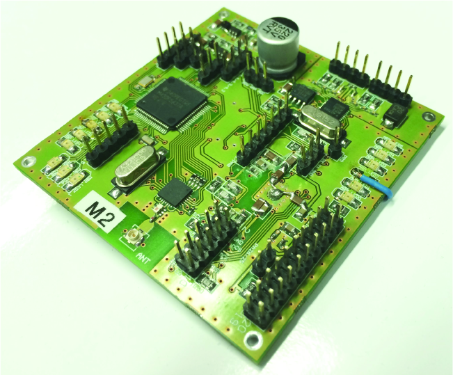
WVWMS measurement module prototype on two-sided PCB.

WVWMS node structure diagram with relation between two microcontrollers, radio transceiver, ADC, and flash memory.
2.3. WVWMS Network Gate
The network gate is responsible for acquisition of the measurement data and uploading them to the storage and server. Additionally, it should be able to receive remote configuration and calibration commands from the Internet. 3G modem is required for communication with the Internet. The authors propose usage of the ARM board, the BeagleBoard-xM from Texas Instruments. It is controlled by the custom built distribution of the GNU/Linux operating system. The IEEE 802.15.4 interface is connected to the ARM board through the USB and seen as a serial connection. It enables usage of Point-to-Point Protocol and packet forwarding with 6lbr. The Contiki slip-radio application is used. The IEEE 802.15.4 interface is based on the communication part of the measurement module and uses the same ICs and most of the PCB layout. Figure 7 presents the hardware. USB board is detachable, enabling direct access to serial interface. There is a second interface for Contiki debugging and exposed JTAG interface.

The IEEE 802.15.4 interface similar to the communication part of measurement module, the USB interface is detachable.
The application running on the Linux board is responsible for receiving packets from the measurement network and uploading them to a remote server. The Internet connection is provided by the USB UMTS modem and controlled by the WvDial tool. The dedicated script controls connection status and resets the modem if necessary. What is more, when the Linux board is not responding, external hardware conducts hard reset of the board. The USB gate enables hard reset of the modem without rebooting the board. This solution improves reliability of the system and as a result, on-site maintenance time is decreased. If the Internet connection is unavailable, measurement data can be stored in internal SD flash storage. The structure of the WVWMS network gate is presented in Figure 8.

WVWMS gate structure, Linux platform connected to the WVWMS interface, USB modem, and Power Management Board.
3. Hybrid Power System for WVWMS
Power supply subsystem, which is common for both the WVWMS gate and TRS, utilises energy harvesting due to a fact that the bridge is located in a long distance from the nearest power line and the systems need to operate uninterruptedly. Two various power sources are planned to be used in order to prevent energy shortage. A small wind generator (Hyacinth P-300 W, rated output power of 300 W at 12 V) will deliver power to cover deficiencies when weather conditions are not favourable for solar panels (four MH-30 panels, 30 W output power at 12 V) to generate sufficient amount of energy to maintain uninterrupted WVWMS and TRS operation (especially in winter and in nights). On the other hand, when wind is not strong enough for a wind generator to rotate, it is predicted that solar panels should produce necessary amount of energy. However, the system will utilise energy storage mechanism to solve the problem of short-term weather changes (several consecutive cloudy and windless days).
The power budget estimation was performed for both TRS with WVWMS gate before actual power system design. Power from the solar panels was calculated as their nominal power multiplied by a ratio of average insolation (for a given season in central Poland) to insolation value at which the nominal power can be achieved (1000 Wm−2). Average insolation is measured for horizontal plane while the panel surface is inclined to this plane (with an angle of about 30 degrees). This makes direct sun light rays to form larger angle with the panel surface (maximum angle of incidence on horizontal plane varies from 15 to 62 degrees in the considered location). Hence, true irradiance of the panels will be higher.
Power from the wind generator was estimated using average seasonal wind speeds (central Poland, elevation of 5 meters above ground). The first step was calculation of probabilities for various wind speeds according to Weibull distribution with shape factor of 1.7. Next percentage power (relative to nominal power available at 12.5 ms−1) was calculated for each wind speed assuming that power is proportional to a wind speed cubed. Minimum wind speed for the generator to rotate and maximum generated power level were taken into account. Finally, each estimated probability for a given wind speed and a corresponding percentage power level were multiplied and then all obtained values were summed to give an expected power level.
Predicted power consumption was calculated for all internal circuits taking into consideration their supply voltages and currents in active and sleep modes as well as average percent of time of staying in a given mode. An average number of trucks passing through the bridge were assumed to have a value of 5 per hour while a total number of cars were predicted as 50 per hour (according to on-site traffic observations). The first parameter was used in TRS power consumption calculations (activity of sensor communication and synchronization with WSS). Moreover, one transmission per hour using 3G modem was assumed. The total number of cars per hour was used in WVWMS gate power consumption evaluation. Power processing efficiencies of necessary switching converters were also considered in the computation of consumed power. The results shown in Table 1 confirmed that a positive power margin can be expected in all conditions.
Power budget estimation results.

The Energy Harvesting Power system is based on Energy Harvesting Controller (EHC) and additional power processing circuits (DC-DC converters) for output voltage regulation to necessary levels. The EHC consists of DC-DC boost converters for the solar panels and wind generator, current summing circuit, and microcontroller measurement and control module with external communication interface. Block diagram of the EHC is presented in Figure 9.

Block diagram of EHC with wind turbine, solar cell, and two batteries.
The power generated by both the wind generator and solar panels is stored in a set of two 12 V gel valve-regulated lead-acid batteries of 26 Ah capacity. The batteries are connected in series which makes it necessary to increase output voltage of both the solar panels and wind generator.
A DC-DC converter based on TPS43060 IC from Texas Instruments is used for boosting output voltage of the solar panels from an input
A MOSFET switch controlled by the microcontroller connects parallel resistor to wind generator output when wind is too strong. The current summing circuit is implemented as double parallel connections of STPS20SM60 power Schottky diodes and SPV1001 switches. The Schottky diodes can conduct current at startup. The MOSFET switches enable much lower forward voltage drop than the diodes.
The rest of power processing circuits is based on step-down switching converters with battery under-voltage control. One of them, based on LM43603 Simple Switcher IC from Texas Instruments, delivers 3.3 V supply for the microcontroller part.
Power monitoring is performed by the microcontroller measurement and control module. The microcontroller applied is ATmega644P from Atmel. It cooperates with ADE7953 energy measurement IC from Analog Devices and bq78412 battery monitor IC from Texas Instruments. The first IC is responsible for measurement of wind generator and solar panel output currents. The second IC measures battery voltage, current, and ambient temperature to calculate remaining charge and operational time. The microcontroller communicates with OMAP using USB interface (FT232RL IC). It can also reset 3G modem, TRS OMAP, and WVWMS gate when necessary.
PCB for the EHC was designed (according to EMC rules and with heat dissipation considered) as a two-layer board with 100 × 150 mm dimensions. Figure 10 presents the view of the EHC PCB with all its components.

Printed circuit board of EHC, dedicated to TULCOEMPA project.
4. Data Acquisition, Storage, and Presentation
Data acquisition system is responsible for data transmission, storage, processing, and presentation.
It was designed to accommodate various measurement systems, one of them being the Wireless Vehicle Weight Measurement System.
Due to integration of data from various measurement systems main requirement for the data acquisition system is flexibility of implementation and support for different data transmission channels. Currently, the system has modules that support channels of Representational State Transfer (REST) [15, 16] and sockets [17], but virtually any communication channel can be added to the system. In order to provide scalability of the system, it is modularised into two main component types, broker and data processing and presentation. A diagram showing its structure is presented in Figure 11.
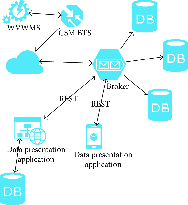
Data acquisition system diagram, WVWMS communicates with server through the Internet.
Each module has a different set of requirements imposed. The broker module is responsible for receiving measurement data from the remote system and providing data for data presentation software.
A module enabling connectivity for a specific measurement system is written as a separate library that can be easily included in the broker. Due to maintainability currently developed modules, including the one for WVWMS, are implemented as self-sufficient; that is, they do not require additional resources on the host server to work.
Java was chosen as the primary programming language of the project due to portability, good documentation, good community support, large repositories of free and open-source libraries and availability of tools, and last, but not least, an ease of programming.
While the broker component requires additional modules to be written in Java and integrated, data presentation application programming language is not limited to Java. Thanks to decoupling of components, it can be written in an arbitrary programming language.
Nevertheless, the current version of data presentation and processing application has been implemented as a web application using Java, HTML, JavaScript, and CSS.
The data presentation module is written using Model-View-View Model paradigm. This makes it possible to implement many different user interfaces, while using only one server backend, that is, desktop application and mobile application.
The server backend is responsible for retrieving data from the broker, storing it locally, processing using business logic, and providing processed data, ready for visualisation, to the user interface application.
The server backend is implemented as a Java Servlet [18] application. Only one resource is required, that is, a relational database. For the purpose of the project PostgreSQL implementation was chosen.
WVWMS data transmission was designed and implemented to fulfil specific requirements: data integrity and support for security. The data integrity means assuring accuracy and consistency. This has also been considered with respect to data storage. In order to assure data integrity, the authors considered communication channel, data transmitter, and data receiver. GSM was chosen as the physical communication channel, because of distributed nature of the system. Due to the requirements for data integrity and communications reliability logical communications are conducted over HTTP [19] using REST. Because of reliability, a common approach of HTTP over TCP/IP [20] is used.
Security is implemented in two aspects: authorisation and encryption. The authorisation is implemented using HTTP Basic Authentication, which enables sending username and password in HTTP header. Because the Basic Authentication does not provide confidentiality of data, the channel is further secured using HTTP over SSL [21].
The selected REST methods with their responses are presented in Algorithm 1.
[{ { [ { [ { { {
5. Conclusion
In conclusion, the paper has presented challenges and proposed solutions for architecture of the Wireless Vehicle Weight Measurement System, which is a part of the TULCOEMPA project. Authors objective was to design and develop a road scale system enabling multipoint vehicle weight with the single network sink. Proposed platform is capable of weight measurement based on electrical strain gauge weight pads and in-node data processing. Communication is wireless, with mesh networking. The block schema of designed WVWMS installation has been introduced and described in detail. Due to lack of mains, all installations are powered by Hybrid Power System. Energy Harvesting Controller cooperates with both solar cells and wind generators. The controller enables efficient energy harvesting from both power sources as well as monitoring of generated and consumed power levels. Additionally, the paper described design of vehicle weight data acquisition software architecture. The approach using REST API provides easy to understand and implement API, with readily available lightweight tools, that is, curl in Contiki, which enables easy client implementation.
Footnotes
Conflict of Interests
The authors declare that there is no conflict of interests regarding the publication of this paper.
Acknowledgments
The authors would like to thank all members of the TULCOEMPA project, including Department of Concrete Structures, Swiss Federal Laboratories for Materials Science and Technology EMPA, and Department of Microelectronics and Computer Science.