
Abstract
Generally, one fixed camera is used to take still or dynamic images and extract proper information from the captured images. However, the process of analyzing images through the use of one camera is very sensitive to neighboring environmental factors, such as illumination, background, and noise; thus, it is hard to guarantee precision. To extract proper information from images more precisely in visual sensor networks, this paper proposes an image-switching strategy where, among different types of installed cameras, the one camera best suited to neighboring circumstances is chosen. The proposed strategy is to first receive initial images as input data and then extract multiple features representing neighboring circumstances from the input images. Subsequently, it is to define the neighboring circumstances metric, which is the weighted sum of the extracted features, and to dynamically switch cameras to obtain images in accordance with the neighboring circumstances. The results of the experiment show that the proposed dynamic switching strategy reliably chooses, from among different cameras, the one camera that is best suited to the neighboring circumstances.
1. Introduction
With the rapid development of visual sensors, wireless communication, pattern recognition, and relevant technologies, visual sensor networks, which are widely deployed, have been distributed highly efficiently in terms of cost and practicability [1–3]. The visual sensor networks are usefully applicable to a wide range of commercial and military application programs, such as applications for video monitoring, smart home, traffic monitoring, movement tracking, and terror prevention [4–7].
A visual sensor network can contain various factors, including different types of sensors, a dedicated communication network, and a proper routing technique for power supply. Among them, a camera for taking scenes is very important because it greatly influences the performance of its accompanying image-processing work. Generally, the cameras used most in computer vision and pattern recognition fields are stereo cameras [8], structured-light cameras [9], TOF (time-of-flight) cameras [10], infrared cameras [11], and thermal imaging cameras [12].
The stereo camera [8] uses two lenses to discern an object three-dimensionally, just as human eyes do. The stereo camera is one of the most widely used camera types but is unable to discern an object when illumination is too bright or too dark. Additionally, the camera is unable to determine corresponding points for objects, such as a wall without texture, and thereby fails to obtain distance information. The structured-light camera [9] can be interpreted in the same way of geometrically replacing one lens of a stereo camera with a projector. The structured-light camera is able to determine corresponding points, even in conditions of poor illumination and texture, but has the disadvantage of slow speed. The TOF camera [10] radiates light-wave energy, such as ultrasound and laser, to an object and calculates the returning time of the light wave from the object to measure a distance from it. Therefore, once circumstances change, it is hard for such a camera to analyze a sound wave. The infrared camera [11] uses infrared rays to create images in a manner similar to general cameras, which use visible rays to make images. In other words, the infrared camera detects infrared energy radiated out of an object by using its detector and then turns the detected energy into an image. The infrared camera is able to obtain the same quality of images at night as in the day and to obtain images at a long distance. However, such a camera is expensive. The thermal imaging camera [12] is a device that visually displays thermal energy radiated out of a subject's surface. The camera is applied to various areas, but the higher resolution the camera has, the more it costs.
Most conventional image-processing techniques use one type of camera to capture scenes, making it difficult to obtain images optimized for neighboring circumstances, such as illumination, background, and noise. Therefore, this paper discusses the installation of multiple cameras in a visual sensor network environment and proposes a strategy to dynamically choose the most suitable camera from multiple cameras on the basis of multiple features. Figure 1 illustrates the overview of the dynamic image-switching algorithm proposed in this paper.

Overview of the proposed system.
As shown in Figure 1, the proposed dynamic switching strategy first receives initial images as input data and extracts various features representing neighboring circumstances from the input images. The strategy then defines the metric in the form of the weighted sum of the extracted features and dynamically switches cameras in accordance with neighboring circumstances. In other words, the strategy is to reliably choose the camera that is best suited to neighboring circumstances among the installed multiple cameras, as well as to capture and analyze scenes with the chosen camera.
The rest of the paper is organized as follows. Section 2 describes previous studies related to the cameras used in the computer vision area. Section 3 explains the technique to extract multiple features representing neighboring circumstances. Section 4 presents the algorithm to switch multiple cameras dynamically. Section 5 shows the results of the experiment conducted to compare and evaluate the performance of the proposed strategy. Section 6 presents the conclusion of this paper and proposes future research directions.
2. Related Works
With the development of multimedia technologies and the falling cost of relevant hardware devices, various types of cameras have been released and applied to many different areas. Of the cameras currently being used, the following are those most widely used.
The stereo camera is one of the most generally used camera types [8]. Such a camera has a separate image sensor and a film frame for each lens, consisting of two or more lenses. Accordingly, the stereo camera employs a time differential between two lenses to obtain three-dimensional distance information, just as human eyes do. Stereo cameras may be used for making stereo views and 3D pictures for movies or for range imaging. Usually, the distance between two lenses in a stereo camera is set to the distance between two human eyes. The baseline of a stereo camera may be longer than the distance, but there is no guarantee of naturalness of the images. Although stereo cameras are universally used, they are unable to determine corresponding points for objects such as a wall without texture. Therefore, the camera fails to obtain depth information [13].
In the case of a structured-light camera, as shown in the system architecture of Figure 2, one of the stereo vision system's two camera lenses is replaced with a device to project light. By projecting the geometrically patterned light, known as structured light, the camera provides corresponding points of stereo vision to easily solve the problem of corresponding points [9]. Such a structured-light-based distance measurement technique has smaller operations to solve the issue of corresponding points and provides multiple corresponding points; thus, it is capable of calculating a large amount of distance data. However, compared to other techniques, it takes more time [14].

Principle of structured-light camera.
The basic principle of a TOF camera is to radiate a strong ray of light forward from the camera and detect its returning reflected light to measure a distance [10]. For the radiating energy of a TOF camera, ultrasound waves are used as sound waves and laser lights are used as light waves. In the case of a sensor using ultrasound waves, it is hard to measure a distance at one accurate point in the real world because of the characteristics of ultrasound waves, and only a representative distance value within a given range of angles in the real world is calculated. In the case of the time delay method using a laser, such a sensor is a one-dimensional sensor type to obtain distance information at one point of the real world through one measurement. In this case, multiple measurements are required to expand two-dimensionally or three-dimensionally [15].
The infrared camera detects infrared energy radiated from an object by using its detector and turns the detected infrared energy into electrical signals to display images two-dimensionally [11], as shown in Figure 3. Infrared light is not invisible and is an electromagnetic wave, which is longer than that of red color light. The infrared camera is made by combining a lens with a sensor that responds to infrared rays. Generally, a CCD or CMOS sensor responds to both visible and infrared rays. Therefore, by applying a filter to a black and white camera, it is possible to pick out the infrared rays; with the control of a gain, invisible infrared regions are presented. Most infrared cameras support unicolor implementation, but some support multicolors. Generally, the infrared camera is capable of obtaining the same quality images at night as in the day and can obtain images at a long distance, but it is rather expensive [16].

Principle of infrared camera.
The thermal imaging camera uses infrared lights, which are radiated out of an object's surface, to look at the surface state through temperature distribution imaging [12]. This process is made possible because thermal energy changes infrared waves or speed. Usually, the infrared light emitted by an object with heat has different waves than the infrared light of a cold object. An infrared sensor converts such a wave difference into an image. Generally, the higher heat an object has, the more infrared light it emits. The brightest color of a thermal imaging camera is traditionally white, its intermediate temperature is generally red or yellow, and its darkest color is blue; temperature-related scales are displayed next to an image. The thermal imaging camera features fast and visible diagnosis outputs. However, thanks to expensive infrared sensors and optical lenses, the thermal imaging camera's production cost is relatively high and the camera can be damaged by the temperature of the object being measured [17].
3. Extraction of Multiple Features
Usually, the work of extracting main features robustly from images is very important in subsequent image processing [18]. To find the features of the circumstances around a camera, this paper extracts three features: illumination, edge, and depth. In addition, to minimize the influence of noise at the time of extracting the features, an input image is first split into regular square blocks with
For the illumination feature, this paper uses the I value in the

In this paper, the illumination feature of an image captured at a time is defined as in (2). Here, N represents the total number of blocks in the image;

For the edge feature, the Canny edge [22] is extracted from an input image. Edge means a pixel located at the border of two areas where luminance intensity sharply changes. Generally, when the edge extracted from an image is used, it is possible to find the location of an object in the image and obtain information on the shape and size of the extracted object. In particular, it is possible to identify how much texture exists in the image. To obtain the Canny edge, this paper first convolves a Gaussian kernel—as shown in Figure 4—in the input image

Gaussian function.
Next, a differential operator is applied to the smoothed image to calculate the sizes of the vertical and horizontal edge; thus, the size and direction of the edge are calculated. Lastly, a non-maximum suppression process (to detect the edge with pixel thickness) and a double thresholding process (to connect edge points) are performed [23]. In this paper, the edge feature of a given image is defined as shown in (3). Here,

This paper uses the depth feature [24] as the third feature. The basic concept of extracting depth information from left and right input images is illustrated in Figure 5.
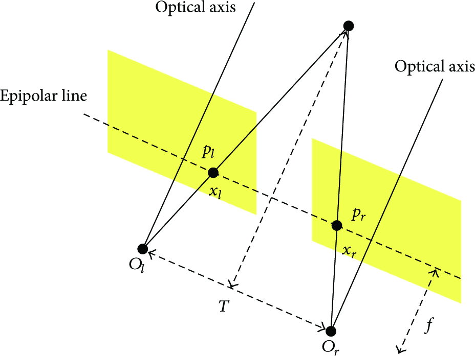
Overview of depth extraction.
As shown in Figure 5, let us assume that P is one point in the real world;


In this paper, the depth feature of a given image is defined as in (6). Here,

4. Weight-Based Image-Switching Strategy
To combine the three features extracted in the previous step, this paper uses weighting factors [26, 27] to define the complexity metric of neighboring circumstances in the sum of their weights. Subsequently, the defined metric is used to dynamically choose, from among multiple cameras, the one camera best suited to the neighboring circumstances. In this paper, the complexity metric is extracted from the initial input image with the use of

In (7), α, β, and γ are the weighting factors used to determine the importance of each term. Each weight is a value between 0 and 1, and the sum of the three weights is 1. In (7), as shown in Figure 6(a), if

Changes in terms for each feature.
After the complexity metric of circumstances is extracted with the use of (7), the following if-else rule based on two thresholds is applied to dynamically switch cameras. In other words, when the complexity metric
IF THEN stereo camera is activated ELSE IF THEN TOF camera is activated ELSE IF THEN infrared camera is activated END
Algorithm 1
The dynamic camera-switching technique, based on the defined rule with the complexity metric and thresholds, can be described similarly to the method of choosing a camera based on how large the extracted three feature values are, as shown in Table 1.
Choice of camera according to features.

Figure 7 illustrates the flowchart of the proposed algorithm to dynamically select a camera on the basis of the complexity metric of circumstances.

Dynamic switching process of images.
5. Experimental Results
For the experiment of this study, a computer that has a Pentium Core 2 Duo 2.66 GHz CPU, 8 GB memory, and Microsoft Windows 7 operating system was used. The software development tools used to implement the image-switching algorithm proposed in this paper are Visual C++ integrated development environment, MFC (Microsoft foundation class) library, and OpenCV [28]. The image database used for the experiment consists of various images captured by cameras in different types of indoor and outdoor circumstances without any specific constraint conditions.
The cameras used in this study are the Bumblebee 2 of Pointgrey [29] as a stereo camera, Kinect 2 of Microsoft as a TOF camera [15], and WMK-H302 of Wonwoo Engineering as an infrared camera [30]. In the different circumstances of illumination, edge, and distance, the proposed image-switching algorithm was applied to the experiment of this study. Figure 8 illustrates an example of the input image, the intensity image, the infrared image, and the depth map image used by the proposed algorithm.

An example of the images used.
Figures 9(a)–9(f) display an example of the images captured in different edge circumstances: “very plentiful,” “plentiful,” “normal,” “poor,” “very poor,” and “completely poor.” Figure 10 shows the edge images extracted from the input images in Figure 9.
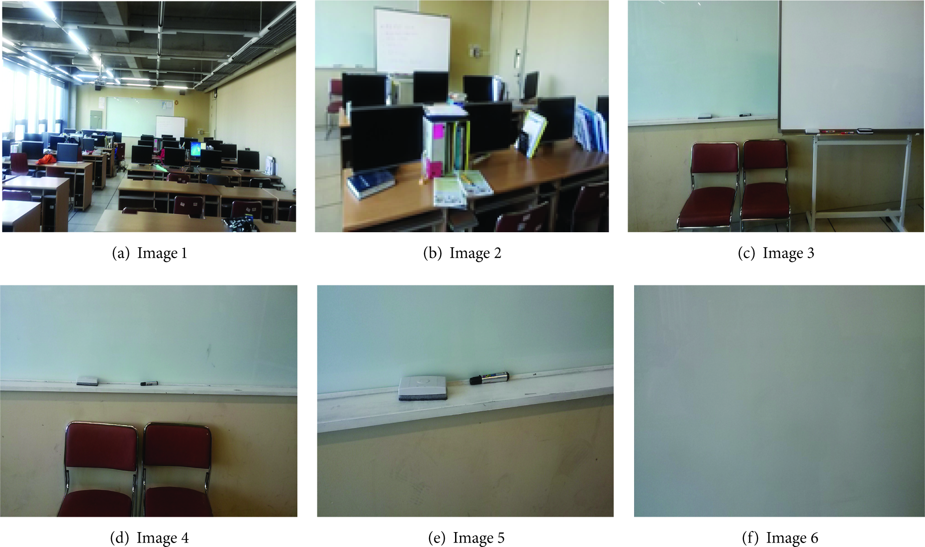
Images with different edgeness.

Edge images.
Tables 2–4 present the overall camera types, which are dynamically chosen by the proposed image-switching algorithm based on the illumination, edge, and distance in the neighboring circumstances. In Tables 2–4, ST, TF, and IR stand for stereo camera, TOF camera, and infrared camera, respectively. It was difficult to present the illumination, edge, and distance on one three-dimensional table with three axes. Therefore, this paper presented three two-dimensional tables, each representing camera choice according to the combination of two features.
Choice of camera based on illumination and edge.

Choice of camera based on edge and distance.

Choice of camera based on distance and illumination.

To judge whether the proposed image-switching algorithm is effective for actual situations, the proposed algorithm was applied to the detection of a moving object. That is, the proposed switching algorithm was used to detect a moving object through block-based motions and depth maps extracted from the captured images. Subsequently, the precision rate in (8) and the recall rate in (9) were applied to measure the accuracy of moving object detection on average according to each method:

Figures 11-12 illustrate the graphs of precision and recall rates. As shown in Figures 11-12, the proposed method was better than the existing methods in terms of moving object detection. In particular, the proposed method chose the infrared camera to detect a moving object when the illumination was bright or dark and when an object was at a long distance. It used the stereo camera when the edge was plentiful and chose the TOF camera when the edge was poor. The process of detecting an object with the use of one fixed camera causes many errors when the neighboring circumstances are bad. Because the proposed method dynamically chooses the camera best suited to neighboring circumstances to detect a moving object, it offers better accuracy than other methods.

Precision rates.

Recall rates.
To sum up, the dynamic switching strategy proposed in this paper effectively integrates and applies the diverse features representing neighboring circumstances to reliably choose the one camera best suited to the current situation. In this sense, it is expected that the proposed algorithm will be useful when applied to a hybrid camera environment based on multiple cameras, which will be used often in the 2D or 3D computer vision and pattern recognition area.
6. Conclusion
To extract proper information from continuous input images more precisely in visual sensor networks, this paper proposed an image-switching strategy where, among different types of installed cameras, the one camera best suited to neighboring circumstances is chosen. The proposed strategy is to first receive initial images as input data and then extract multiple features representing neighboring circumstances from the input images. Subsequently, it is to define the neighboring circumstance metric, which is the sum of weights of the extracted features, and to dynamically switch cameras to obtain and analyze images in accordance with the neighboring circumstances.
According to the experiment to compare and evaluate the performance of the proposed method, the proposed dynamic switching strategy reliably chose, from among different types of cameras, the camera that was best suited to the neighboring circumstances. In particular, for dynamic switching, the proposed method applied a weighting factor to each feature to define an integrated metric, thus revealing that the method is not sensitive to changing neighboring circumstances and works robustly.
In future studies, the proposed dynamic switching algorithm should be applied to more types of cameras than the three types used in this paper. In addition, more research will be continuously conducted to obtain the robust features representing the neighboring circumstances.
Footnotes
Conflict of Interests
The authors declare that there is no conflict of interests regarding the publication of this paper.
Acknowledgment
This research was supported by Basic Science Research Program through the National Research Foundation of Korea (NRF) funded by the Ministry of Education, Science and Technology (2011-0021984).