
Abstract
A number of studies have been actively conducted to address limited energy resources in sensor systems over wireless sensor networks. Most of these studies are based on energy-aware schemes, which take advantage of the residual energy from the sensor system's own or neighboring nodes. However, existing sensor systems estimate residual energy based solely on voltage and current consumption, leading to inaccurate estimations because the residual energy in real batteries is affected by temperature and load. This misinformation makes a complete nonsense of existing energy-aware research, which is not allowed in reliable WSN applications. In this study, therefore, an efficient residual-energy estimation scheme is proposed in consideration of not only the voltage but also the temperature and load characteristics of batteries. The performance of the proposed scheme was verified through an experiment and simulations in the actual environment, and its effect gets more notable when the scale of the WSN goes larger.
1. Introduction
One of the main characteristics of wireless sensor networks (WSNs) is that they have limited resources. The limited energy of the battery is an important factor in determining the lifespan of a sensor network. A number of papers [1–5] in the area of WSNs have proposed a system configuration and routing scheme in consideration of the residual energy in a sensor system. For example, information about residual energy can be employed in system-level maximization, such as the duty cycle control or transmission-range control, as well as in network-level maximization, such as energy-aware routing schemes.
Until now, a linear estimation or a voltage-based estimation has commonly been used to estimate the residual energy which is the most relevant factor in energy-aware operations. However, these schemes lead to substantial errors because they do not take into account the characteristics of batteries and the environments of sensor networks. It is evident that estimation methods based solely on voltage are inaccurate, because changes to the voltage resulting from the battery's discharge are not linear and because batteries are highly sensitive to changes in temperature and load. An accurate estimation of the residual energy in batteries is pertinent to energy-aware research and can play an important role in enhancing the efficiency and reliability of existing energy-aware routing schemes and systems.
Therefore, this study proposes an efficient method for estimating residual energy, by considering the performance characteristics of battery according to the temperature and load in batteries, along with its voltage. This can be possible by utilizing a small database which contains the useful residual energy information measured in the various temperature and load environments. In order to prepare this database, we conducted numerous experiments using the UBee430 mote which is based on TelosB mote [6]. TelosB is a verified battery-based sensor system widely used in WSN-related research. It uses two AAA alkaline batteries and equips MSP430 microprocessor and CC2420 transceiver with various sensors including voltage and temperature sensors.
In general, both a manganese battery and an alkaline battery are used as a primary cell, but the alkaline battery is usually used for the sensor system since it has an advantage to operate for a long period due to the low self-discharging rate. Therefore, the proposed scheme focuses only on the alkaline battery. In addition, there are various lithium-based rechargeable batteries in a secondary cell. However, in the case of lithium-based battery, there is no relationship between the amount of residual energy and the voltage level. Therefore, it is hard to estimate the amount of residual energy in lithium-based battery without any extra circuit.
Through the various experiments in a real environment, we demonstrate that the proposed scheme not only uses less memory space but also estimates more accurate residual energy with lower computation overhead, compared with the existing linear-estimation methods and voltage-based estimation methods. In addition, the proposed scheme is shown to improve the imbalance of energy consumption and the lifespan of the entire network more than existing schemes. Furthermore, its effect gets more notable when the scale of the WSN goes larger.
Before introducing the proposed scheme, Section 2 introduces previous studies that estimate residual energy and also describes the problem of predicting residual energy using them. Section 3 introduces which factors should be considered but overlooked in previous schemes when estimating the residual energy in batteries. Then, Section 4 explains the scheme proposed in the present study, and Section 5 presents the performance evaluation through experiments and simulations. Finally, conclusions are drawn in Section 6.
2. Related Work
In this chapter, previous studies that estimate the survival time of a battery-based sensor system are discussed. In [7], a tool that can simulate the survival time of a battery-based sensor system was proposed. In this study, the current consumption of each hardware component in a Mica2 sensor system was analyzed. In addition, an application and operating system (OS) code-based power-consumption estimation model called AEON was developed. Furthermore, the survival time of the entire network and its sensor systems was predicted using AEON. In [8], an online energy-estimation scheme based on software was proposed for battery-based sensor systems. To reduce unnecessary energy consumption, it frequently turned on and off various hardware components owing to the characteristics of wireless sensor systems. According to such characteristics, a timestamp was recorded whenever the state of a hardware component changed, in order to calculate the energy consumption of the system in [8]. They claimed that their scheme reduced additional costs and energy consumption because the energy consumption of the components was calculated using software rather than the additional hardware required by existing hardware-based online energy-estimation schemes [9].
The schemes described above are using the linear-estimation scheme which calculates residual energy on the basis of the assumption that the remaining energy will decrease linearly as the battery's voltage decreases. The residual energy at the maximum allowable voltage and minimum required voltage in a sensor system are 100% and 0%, respectively. Figure 1 shows a graph that compares an existing linear estimation with real experimental results. The maximum allowable voltage was produced when two fully charged AAA alkaline batteries were serially connected, whereas the minimum required voltage was defined as occurring when a correct sensing value could not be determined because of under-voltage. An environment with a constant temperature of 12°C was maintained. To ensure an appropriate load, an RF module was turned on and remained in a ready state for a period of time. Then, approximately 20~30 mA was maintained throughout the experiment. The experimental results revealed that a linear estimation showed the maximum error exceeding 100% at 1.8 V. The voltage change in the alkaline batteries [10] was nonlinear, and thus the estimation of residual energy using a linear estimation was inaccurate and incapable of accurately estimating the residual energy. Such a linear estimation is preferable for use with lithium-ion batteries [11], with which changes in voltage are linear.

Estimation of residual energy from battery voltage and measured curve.
Reference [12] claimed that changes to the battery voltage represent the most important factor in creating an energy model for battery-based sensor systems. Reference [12] proposed an energy model through real experiments using TelosB [6], a popular battery-based wireless sensor system. Their proposed model considered the discharge characteristics of battery voltage as follows:

In [13], a new system was proposed to satisfy a target service time for sensor systems. Their proposed system satisfied a target service time by scheduling remaining resources after estimating the residual energy of the battery and the energy to be used. Their study defined an energy level to easily calculate the energy consumption for each service task in a sensor system. The energy level is defined by dividing the current consumption in a hardware component for each of the steps in a sensor system. Because each application program uses different hardware and uses respective hardware differently, a unique energy level is applied for each hardware component. Energy consumption per unit of time for a corresponding program can be estimated by the sum of the energy consumption of all components. Moreover, a battery model was defined to obtain the residual energy in a sensor system. Reference [13] found that residual energy based on battery voltage was nonlinear, so they utilized the results from three experiments, testing a Mica2 sensor system as a battery model. Figure 2 shows the battery model proposed in [13] as a graph. Models proposed in [12, 13] calculated the survival time of the sensor system using the mean value of the current, calculated experimentally. However, it cannot determine the survival time accurately merely from the precalculated value of the current without considering temperature, because the current in a real battery can differ depending on changes in temperature even if the same application programs are run. In this study, we propose a scheme that can simply but accurately estimate the residual energy which is the most pertinent factor for calculating the survival time of a sensor system.

Battery discharging characteristic of the MICA2 mote.
3. Important Factors for the Estimation of the Battery's Residual Energy
3.1. Analysis of Changes in Residual Energy over Variable Temperature Environments
A battery delivers a current through a chemical reaction by creating a potential difference between the metal ions and the electrolytes. Such a chemical reaction is greatly affected by temperature, such that usable energy can differ depending on the exposed temperature, despite the same voltage in the battery. In this chapter, we describe the experimental analysis of the effect of temperature on the residual energy in a battery.
In the experiment, a relationship between the residual energy and the voltage of a battery was observed in an environment where a constant temperature was maintained. A UBee430 sensor system that used two AAA alkaline batteries was employed, and a 20~30 mA load was maintained while the RF module was held in a running state. To maintain a constant temperature, a refrigerator and a specially manufactured constant-temperature box were used. For voltage, values provided via an ADC voltage sensor mounted on the UBee430 were recorded, while an Agilent 6.5-digit digital multimeter was used to measure and record the current. A logging environment was set up by using specially implemented software in a Linux environment with TinyOS to record the voltage and current values in real time. Figure 3 shows a graph of changes in the residual energy according to voltage over a temperature range of 0°C~38°C with a gap of approximately 12°C. Each graph shows that the residual energy that is usable in an alkaline battery can differ according to the temperature and that the residual energy in a battery is not linear to the change in voltage. In particular, a total of 1.38 Ah can be used in a 38°C environment, whereas a total of 0.72 Ah can be used in a 0°C environment, revealing an energy difference of up to 1.9 times, according to the temperature.

Change in residual energy with battery voltage at different temperatures.
As shown in the experimental results, temperature, in addition to voltage, is a crucial factor for estimating the residual energy in a battery-based sensor system. These temperature- and voltage-dependent characteristics of batteries shall be utilized in estimating the residual energy by means of a database.
3.2. Analysis of Changes in Residual Energy over Variable Load Environments
In Section 3.1, residual-energy estimations that did not consider temperature information were shown to differ significantly from the actual residual energy in a battery determined through experimentation. In this chapter, we analyze the relationship between the load in a battery-based sensor system and its residual energy in an alkaline battery. Figure 4 shows the experimental results for changes in the residual energy when the same AAA alkaline battery was used at a constant load, with the load set at 25 mA, 100 mA, and 250 mA. The maximum allowable voltage and the minimum required voltage were set at 3 V and 1.6 V, respectively. According to Figure 4, the energy that is usable for each load is 2.916 Ah, 2.45 Ah, and 1.9 Ah. The usable energy differed considerably depending on the amount of the load, by up to approximately 1 Ah. The higher the load is for a battery-based sensor system, the faster the residual energy is reduced. In summary, the usable energy drops more for higher loads at the same voltage value. Taking this characteristic of alkaline batteries into consideration, we proposed an online/offline residual-energy estimation scheme using temperature and load information in a battery-based sensor system. Through a number of experiments, we verified that the load in a sensor system had 1~5 mA when an RF module was unused, and the load did not exceed 40 mA even when an RF module was used. Actually, such a small load change within 0~40 mA does not significantly affect changes in usable energy. However, if a sensor system is embedded with a high-powered RF antenna or multimedia sensors, the mean load should be reflected in the estimation of the residual energy.

How residual energy corresponds to battery voltage at different loads.
3.3. Analysis of Changes in Residual Energy due to the Battery Recovery Effect
Battery basically has the recovery effect even though the effect is different according to the type of battery [14]. Recovery effect means that battery can recover some amount of energy when it takes a break. Therefore, the duty cycle of the sensor is closely related to the recovery effect. Assuming that the duty cycle is 1, the gain from the recovery effect would be zero since there is no idle time. Thus, the gain owing to the recovery effect increases as decreasing the duty cycle. Figure 5 describes the amount of gain with various duty cycle values. As shown in Figure 5, the gain increases the amount by up to 10 times. However, we have to note that this recovery effect can be reflected in the battery's voltage since the amount of gained energy would increase the voltage of battery after all. Therefore, assuming the residual-energy estimation scheme considers the voltage information, we do not need to consider the recovery effect anymore.

The effect of recovery effect on the residual energy.
4. Efficient Estimation Scheme for Residual Energy
As discussed above, temperature and load are two important factors to consider when estimating the residual energy in a battery-based sensor system. To obtain a more accurate estimate of battery's residual energy, we prepare DB (database) which predicts residual energy from battery voltage at different temperatures and loads. The data in this DB is concentrated at points of rapid change in the battery's characteristics.
Critical temperatures are different for different types of battery. We consider a 1.5 V 2900 mAh AA size alkaline battery [10]. The battery's datasheet indicates that, below 0°C, a drop in temperature of 5°C reduces the available energy by about 500 mAh, until the available energy reaches 250 mAh, at which point the battery is effectively exhausted. Capacity is stable between 0°C and 20°C. From 20°C to 60°C, an increase in 10°C raises the available energy by 500 mAh, until it reaches a maximum of 3300 mAh. At each critical temperature, the relationship between residual energy and voltage is experimented with several important values of loads for typical sensor nodes, and this experimental data is embedded to the sensor as the type of DB. Sensor node can estimate the current residual energy by using this DB using the current temperature and load. Figure 6 summarizes the proposed scheme. Note that the implemented DB can be used for all sensors assuming that every sensor uses the same type of alkaline battery, since the values in the DB reflect the characteristics of the battery according to the voltage, temperature, and load, without reference to the system specification.

Outline of the proposed energy estimation scheme.
A WSN sensor experiences a variable environment, including changes in temperature from day to night, variable insolation, and changes in network topology which cause changes in load. We therefore use a moving average of temperature and load to predict residual energy. A value

Therefore, it is required to estimate the load from the other context of sensor. As shown in (3), we model the load (energy for

However, it should be noted that the constant values described in (3) are different with the node specification. Therefore, the expression for calculating load should be modified according to the sensor specification.
To sum up, as described in Figure 6, the proposed method embeds a DB into the sensor system for estimating the residual energy in the alkaline battery that changes according to voltage, load, and temperature. When residual-energy information is needed, a sensor system senses the voltage information and calculates the moving averages of load and temperature and then performs a lookup to find the residual energy with the voltage value in the corresponding DB. Because of the characteristics of sensor systems, the size of the DB should be limited such that only information regarding the representative temperatures, suitable to the environment where the sensors are arranged, is included in a DB.
One implementation issue of this scheme is that the temperature sensed by the temperature sensor and that of the battery core might be different. However, since general sensor node sleeps periodically and its duty cycle is normally lower than 0.1, the two temperatures described above are rarely different. It may be true that the difference can occur in the specially overloaded node, but the temperature sensor in the sensor system is generally located near the battery; it is expected that the sensory temperature data reflects the temperature of the battery core in some degree.
Residual energy can be utilized to calculate the usable time, which was estimated in previous studies [9, 12]. The residual energy

Despite the simplicity of the proposed scheme, the resulting experimental estimations proved to closely approximate the actual measurements by taking into account the characteristics of alkaline batteries and WSNs (e.g., the sensitivity to temperature and the small load for sensor systems). If the residual energy is estimated accurately, energy-aware scheduling and survival time can in turn be accurately estimated using existing methods, thereby maximizing the performance of energy-aware routing.
5. Performance Evaluation
5.1. Experimental Verification
In this chapter, the proposed estimation scheme described above, in Section 4, is discussed in terms of an experimental verification performed in a real environment, and the results of this verification are introduced. The measurement environment is shown in Table 1. Assuming an environment such as a desert, with extreme temperature changes between the days and nights, the experiment was conducted in an environment where temperature changed periodically between 5°C and 48°C. Voltage, temperature, and current load were logged in real time over the survival time of the sensor system. Note that, with considering the constraints of the storage space, only 9 DBs are inserted, each of which represents the combination of three temperatures 0°C, 20°C, and 40°C and the three loads 10 mA, 20 mA, and 30 mA.
Measurement environment.

Figure 7 shows the results of the experiment. Estimating the residual energy using linear estimation in a temperature-fluctuating environment resulted in the greatest range of error, such that the results using this method are excluded in the figure. In addition, the proposed residual-energy estimation scheme and existing voltage-based estimation scheme [13] were compared on the basis of the real measurements. The voltage-based estimation scheme used a DB for which only voltage was taken into consideration and neither temperature nor load.

Actual experimental result at varying temperatures.
As shown in Figure 7, the voltage-based estimation scheme resulted in severe errors from the beginning, relative to the real measurements. On the other hand, the proposed estimation scheme obtained values similar to the real measurements when the temperature increased rapidly and decreased slowly. Although the proposed scheme produced slightly higher values than the real measurements (as did the voltage-based estimation method) between 12:00 and 20:00, when the temperature was relatively constant, it estimated the amount of residual energy more accurately than the existing estimation scheme during the times when the temperature fluctuated.
Figure 7 also shows temperature and voltage changes in a sensor system over time in addition to residual energy information. In this graph, we found that the battery voltage increased between 22:00 and 05:00 at the same time as temperature increased from approximately 8°C to 48°C. In addition, after analyzing the graphs in the same time-range described above, we also confirmed that the increase in voltage is not linear to temperature increases. Compared with the first fluctuation where the voltage increased by 0.16 V when the temperature increased by approximately 22°C (from 8°C to 30°C), a temperature increase of approximately 18°C (from 30°C to 48°C) resulted in an increase of only approximately 0.05 V in the second increasing fluctuation. Therefore, for the more accurate residual-energy estimation, the temperature as well as the voltage should be considered independently as in the proposed scheme, since these two factors are not linear.
To claim this conclusion more aggressively, we set the simulation environment mimicking this situation and perform experiment again. Through the result of this experiment shown in Figure 8, we can confirm that an existing voltage-based estimation scheme shows a larger difference than the proposed scheme, since it cannot reflect the effects of the temperature on the residual energy. In more detail, the proposed estimation scheme resulted in estimates that correctly align with the real measurements between 0:00 and 12:00. It estimated values that were slightly higher than the real measurements between 12:00 and 9:00 the next day (during which time there was a rapid temperature increase), yet it correctly estimated values in accordance with the real measurements after 9:00. The voltage-based estimation scheme, on the other hand, estimated values that were approximately 0.22 Ah lower than the real measurements throughout the experiment. In addition, it estimated that the residual energy of the sensor system was zero, despite the fact that the system remained operational at 18:00 on the second day.

Reexperiment result at the point of voltage rise.
In summary, the proposed scheme can accurately estimate the residual energy using a DB that is only approximately 3.1 KB in size. Furthermore, the existing voltage-based residual-energy estimation scheme resulted in significant errors in real environments with temperature changes, as was observed through experimentation, verifying that such schemes are unfeasible for application in real environments.
Note that the proposed method embeds a few DBs into the sensor system for estimating the residual energy, which are categorized with the temperature and load. Every DB has the amount of residual energy according to the value of voltage, which is experimented in a relevant temperature and load. The more DB in the system can estimate the more accurate amount of residual energy. However, because of the storage constraint of sensor systems, the size of the DB should be limited so that only information regarding the representative temperatures and loads, at which rapid change in the battery's characteristics occurs, can be included in a DB. Since only 9 DBs are included in the simulated node, the node should approximate the temperatures and loads to these representative values, and this inevitably makes some errors.
5.2. Effect of the Proposed Scheme on the WSNs
The network-simulation results are presented to show how the proposed estimation scheme improved performance of WSN compared with the existing voltage-based estimation scheme [13]. The simulator was implemented using C++, with which not only the proposed scheme but also the existing voltage-based scheme can be used to calculate the residual energy in each node. As mentioned earlier, in the existing scheme [13], the residual energy is guessed with the voltage-energy table which is constructed with base on the experimental results. However, this scheme does not take the effects of the temperature and the load into consideration. These two schemes were tested under identical simulation conditions.
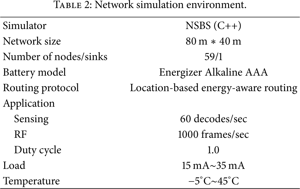
As shown in Table 2, we assume an environment such as a desert, with extreme temperature changes between the days and nights; thus the experiment was conducted in such an environment where temperature changed periodically between −5°C and 45°C. In the case of each node's load, we assume that the load is fluctuating between 15 mA and 35 mA depending on the amount of data the node should relay to neighbor nodes. This load can represent the general load of the sensor network for monitoring environments. Figure 9 shows the trace of temperature and load change over time on a sample node.
Network simulation environment.

Trace of simulated temperature and load over time.
A total of 60 nodes, including a single sink node, were arranged in a deployment area of 80 m in width and 40 m in length. A routing protocol was used to apply energy-aware location-based routing. Each node selected the neighboring nodes that were closer to the sink node than itself, based on the location information, and nodes with more residual energy were given priority. A battery model [10] and an energy-consumption model [6] in the node were implemented to simulate a real environment as closely as possible. Figures 10 and 11 show the number of dead nodes over time and the standard deviation of the residual energy in all nodes when the number of dead nodes increased by 10%.

Number of dead nodes over time.
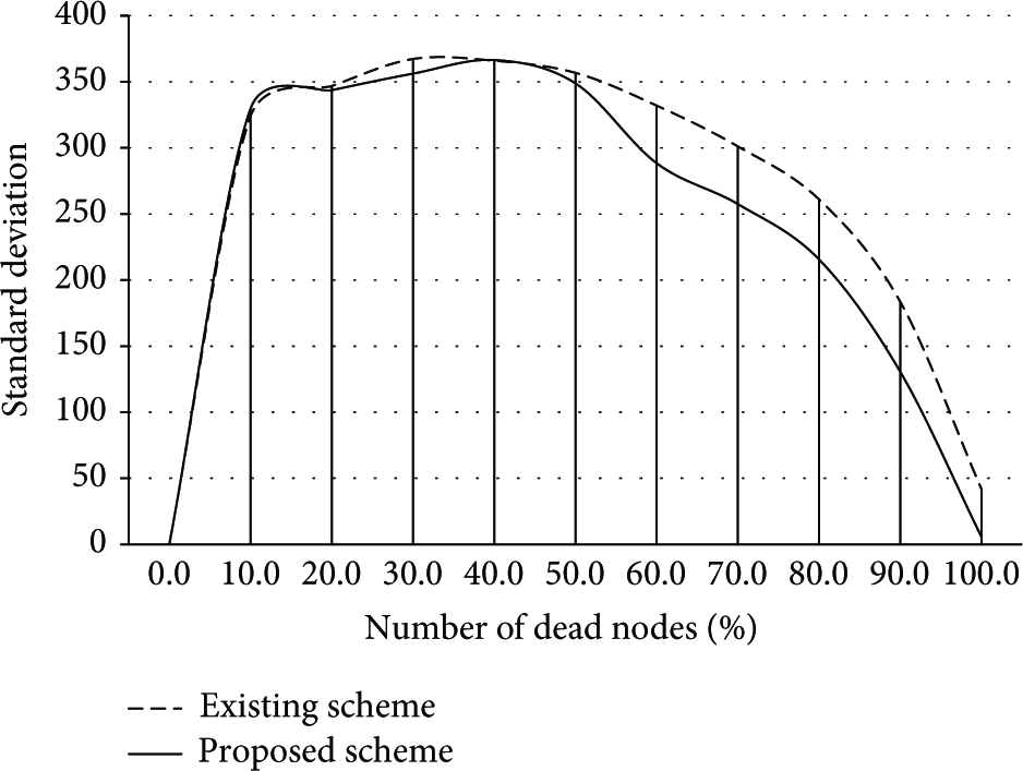
Standard deviation of residual energy.
In the simulation results, the proposed scheme was compared with the existing voltage-based estimation scheme. As shown in Figures 10 and 11, the proposed scheme can estimate the residual energy accurately by reflecting changes in temperature and load, thereby maximizing the energy-aware routing-protocol performance. As shown in Figure 10, the network using the proposed scheme can survive up to 6 hours longer than the existing scheme, through the exact residual-energy calculation. This is because a network cannot operate after more than 50 nodes are dead, outside of a simulated environment. In addition, the energy consumption for the overall network can be unbalanced, given that the nodes around a sink node consume relatively more energy owing to the concentration of traffic directed toward the sink node (which is a characteristic feature of sensor networks [16]). However, Figure 11 shows that when the proposed scheme was used, the standard deviation decreased more after 50% of nodes were dead. Thus, we confirmed that when the residual energy is estimated using the proposed scheme, it is possible to maximize the performance of energy-aware routing, as shown in Figures 10 and 11.
Finally, we measured the network lifetime with various network sizes. As shown in Figure 12, the network applying the proposed scheme sustains longer life than the network with the voltage-based estimation. The result which is worthy of close attention is that the effect of the proposed scheme increases as the network size grows. Since typical WSN consists of a great deal of sensors, our scheme can play an important role to utilize WSN worthily.

Network lifetime with various network sizes.
6. Conclusion
To estimate the residual energy in a battery-based sensor system, the characteristics of alkaline batteries and sensor systems were taken into account. In this study, the temperature- and load-related characteristics of alkaline batteries were discovered through experiments, and an accurate residual-energy estimation scheme was proposed by querying the residual energy from a DB using mean temperature and load as well as voltage information. To calculate the survival time of a sensor system, the problems resulting from existing linear-estimation schemes and voltage-based residual-energy estimation schemes were verified through experimentation alongside the performance of the proposed scheme. Furthermore, a network simulation confirmed that the proposed scheme improved the unbalanced energy consumption and duration for the overall network better than existing schemes.
As mentioned in the introduction, the use of battery-based sensor systems over a WSN must inevitably consider the characteristics of sensor systems: low manufacturing costs, less power, and a longer lifespan. This study proposed an efficient estimation scheme for the residual energy that is used in optimization research in existing energy-aware routing. The proposed scheme considered the characteristics of alkaline batteries and demonstrated that accurate estimations can be made using an embedded DB. The DB used in the proposed scheme considered four different temperatures and loads with a table size of approximately 3.1 KB. TelosB and UBee430, popular battery-based sensor systems, have 1 MB of flash memory, while Mica2 has 128 KB of flash memory. Therefore, the table used in the proposed estimation scheme can be applied to commercial sensor systems that are currently available on the market without any problem.
Footnotes
Conflict of Interests
The authors declare no conflict of interests.
Acknowledgment
This research was supported by Next-Generation Information Computing Development Program through the National Research Foundation of Korea (NRF) funded by the Ministry of Education, Science and Technology (no. 2012M3C4A7032182).