
Abstract
The design of deep submersible pressure hull's structural is one of the core technologies of submersible development of human history. Submersible pressure hulls with fiber-reinforced multilayer constructions have been developed in the recent years as substitutes for classical metallic ring-stiffened pressure hulls; strength and stability are its top priority. This paper investigates the optimum design of a composite elliptical deep-submerged pressure hull under hydrostatic pressure to minimize the buoyancy factor of the submersible pressure hull under constraints on the failure criteria and the buckling strength of the hulls to reach the maximum operating depth. The thickness and the fiber orientation angles in each layer, the radii of the ellipse, and stringers dimensions were taken as design variables and determined in the design process. The optimization procedures are performed using commercial finite element analysis software ANSYS. Additionally, a sensitivity analysis is performed to study the influence of the design variables on the structural optimum design. Results of this study provide a valuable reference for designers of underwater vehicles.
1. Introduction
Many structural elements made of fiber-reinforced composites are increasingly utilized in aerospace, marine, and civil engineering applications [1]. The most important benefits from using such advanced materials are the attainment of high stiffness-to-weight ratio and long fatigue life. An important element of any submersible is the pressure hull. The pressure hull is the main watertight structural component of a submarine that houses personnel, propulsion machinery, weapons and sensor systems, and other sensitive equipment. Pressure hulls are designed to withstand the hydrostatic load associated with diving to depths usually measured in the hundreds of meters [2]. One of the major problems confronted by the designer of deep submersibles is to minimize the weight of the pressure hull and to increase the payload, propulsion, and velocity of submersible vessels, which can be achieved through the advanced hull concept and efficient material systems [3, 4].
Buoyancy requirement for the weight-sensitive structures can be easily met by applying a composite material, which has an excellent specific strength and stiffness to reduce the weight of the structure. The danger of being detected by sonar can be reduced and the resistance to corrosion can be increased because the composite sandwich has excellent sound absorption properties and is stable against the chemical reaction [5]. A submarine designer pointed out that the safety factor of 1.5–2.0 is considered acceptable in most engineering practice [6]. Liang et al. [7, 8] optimized the design of filament-wound multilayer sandwich submersible pressure hulls. The facings become thicker and the core becomes thinner as the operational depth increases. Alvarez et al. [9] optimized the hull geometry to reduce the total resistance. The hull shape resulting from the optimization process reduces (up to 25%) the estimated total resistance. Cui et al. [10] performed the structural optimization of a bulk carrier with two conflicting objectives (weight and fatigue) as a case study. Zu et al. [11] presented the optimal design problem of a half-cell dome profile for filament wound articulated pressure vessels which aims to maximize the structural performance of pressure vessels based on the continuum theory and the Tsai-Wu failure criterion. Adali et al. [12] presented an approach for the optimization of symmetrically laminate cylindrical pressure vessels subjected to strength constraint. The optimization is carried out with respect to the fiber orientations and thickness distributions subject to the Tsai-Wu failure criterion.
Kim et al. [13] designed an automotive composite lower arm using carbon-epoxy composite materials and optimized the stacking sequence of the composite layer to maximize the buckling load capability. The composite lower arm had two times higher stiffness and buckling strength compared to the conventional steel lower arm while having 50% less weight. Lee et al. [14] optimized composite sandwich cylinders under external hydrostatic pressure. Both buckling and material failure were considered. The optimization results suggest that when the core thickness increases, the material failure determines the design maximum pressure instead of the buckling. Tauchert [15] studied the optimum design of a reinforced cylindrical pressure vessel. Messager et al. [16] presented the optimal design of deep submarine by determining the laminate stacking sequences that maximize the critical external buckling pressure, using a genetic algorithm procedure coupled with an analytical model. Bruggi and Taliercio [17] presented a numerical approach for the optimal design of any unidirectional fiber-reinforcement to improve the structural performance of existing structural elements. The Tsai-Wu failure criterion is implemented to detect highly tensile-stressed regions in the existing structural components.
Ca et al. [19] presented a reliability-based load and resistance factor design procedure for subsea composite pressure vessel subjected to external hydrostatic pressure. The longitudinal modulus, inside radius of composite layers, unsupported length, and external pressure significantly affect the design results, whereas transversal modulus, Poisson's ratio, shear modulus, and winding angle have little effects. Maalawi [20] developed a practical approach for enhancing the buckling stability limits of thin-walled anisotropic rings-long cylinders. Bakshi and Chakravorty [21] studied the first-ply failure of thin composite conoidal shells subjected to uniformly distributed load. To achieve high values of the failure loads, the bottommost lamina of the cross-ply laminates should have the fibers oriented along the arch direction.
Chang [24] investigated analytical and experimental first-ply failure loads of laminate pressure vessels subjected to internal pressure loads. Chang and Chiang [25] reported experimental and theoretical first-ply failure loads of antisymmetrically laminate composite plates subjected to central point loads. Prusty et al. [26] reported first-ply failure of laminate cylindrical and spherical shells with and without stiffeners, respectively. Failure due to structural buckling is also a major risk factor for thin laminate cylindrical shells. Anastasiadis and Simitses [27] studied the buckling of long laminate cylindrical shells under external radial pressure using higher order deformation theory. The results provide valuable information concerning the applicability of the various shell theories.
Gohari et al. [28] studied a circular cylindrical thin-walled shell failure made of GRP composite subjected to static internal and external pressure. Deformation, delamination, shear deformation, and microbuckling failure were investigated. Stacking sequence and fiber angle orientations were mainly effective on failure strength. Xiong et al. [29] studied the failure behavior of sandwich-walled cylindrical shells with metallic lattice truss cores and fiber-reinforced composite face sheets under uniaxial compression. The local buckling and face crushing modes can exist together and are the most important modes of failure of the fabricated structure. Graham [30, 31] studied composite pressure hulls for deep ocean submersibles and evaluated some of the popular failure criteria. Hsu et al. [32] studied the curvature effect on stress concentrations around a circular hole in the curved shell and the failure modes of the Guppy type pressure hull under external pressure loading using the finite element method.
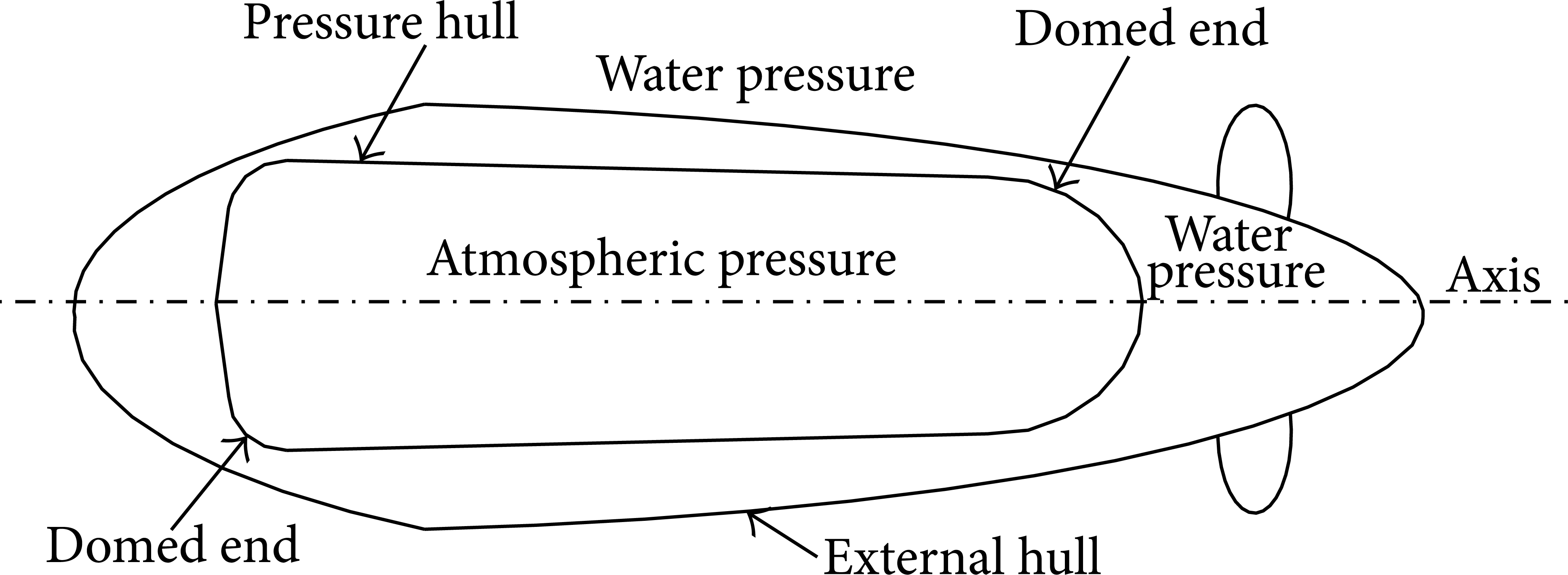
Kolakowski [33] presented a modified Tsai-Wu criterion, which can be used in the multicriterion optimal design of composite structures. Jen [34] presented the optimal design of a small-scale midget submersible vehicle (MSV) pressure hull using a powerful optimization procedure combining the extended interior penalty function method with the Davidon-Fletcher-Powell method. Liang et al. [35] investigated the optimum design of multiple intersecting spheres deep-submerged pressure hull subjected to hydrostatic pressure. Ross [36–38] introduced an alternative design for submarine pressure hull without ring-stiffeners and predicted the four-lobe buckling mode of a corrugated carbon fiber vessel under external pressure. In this study, a composite submarine pressure hull in the form of elliptical cylinder subjected to hydrostatic pressure as shown in Figure 1 is optimized using nonlinear finite element analysis software ANSYS. The objective function is to minimize the buoyancy factor by simultaneously considering the buckling and material failure loads.

Geometry of elliptical submersible pressure hulls.
2. Submarine Pressure Hull
The submersible pressure hull structure form is different according to the structure of submersible pressure shell and material selection principle. The usual shape of a submarine pressure hull is in the form of a ring-stiffened circular cylinder, blocked by end caps, as shown in Figure 2. This is a good structure to resist the effects of external hydrostatic pressure [39]. Figure 3 shows various wall architectures used for pressure hulls which include pure monocoque constructions, gas-storage toroidal tube-stiffener hull wall construction, traditional ring-stiffened hull wall constructions, trapezoid corrugated hull wall construction, ring-stiffened corrugated pressure hull wall construction, and sandwich hull wall construction [7, 18].
The usual shape of a submarine pressure hull.

In this study, an elliptical pressure hull as shown in Figure 1 is proposed for a better space utilization, good hydrodynamic form, and stability; this is better than a spherical form of the same volume and is easy to manufacture. The stacking sequence of the shell cross section is shown in Figure 4. Plies are numbered from the bottom of the laminate upwards. The stacking sequences
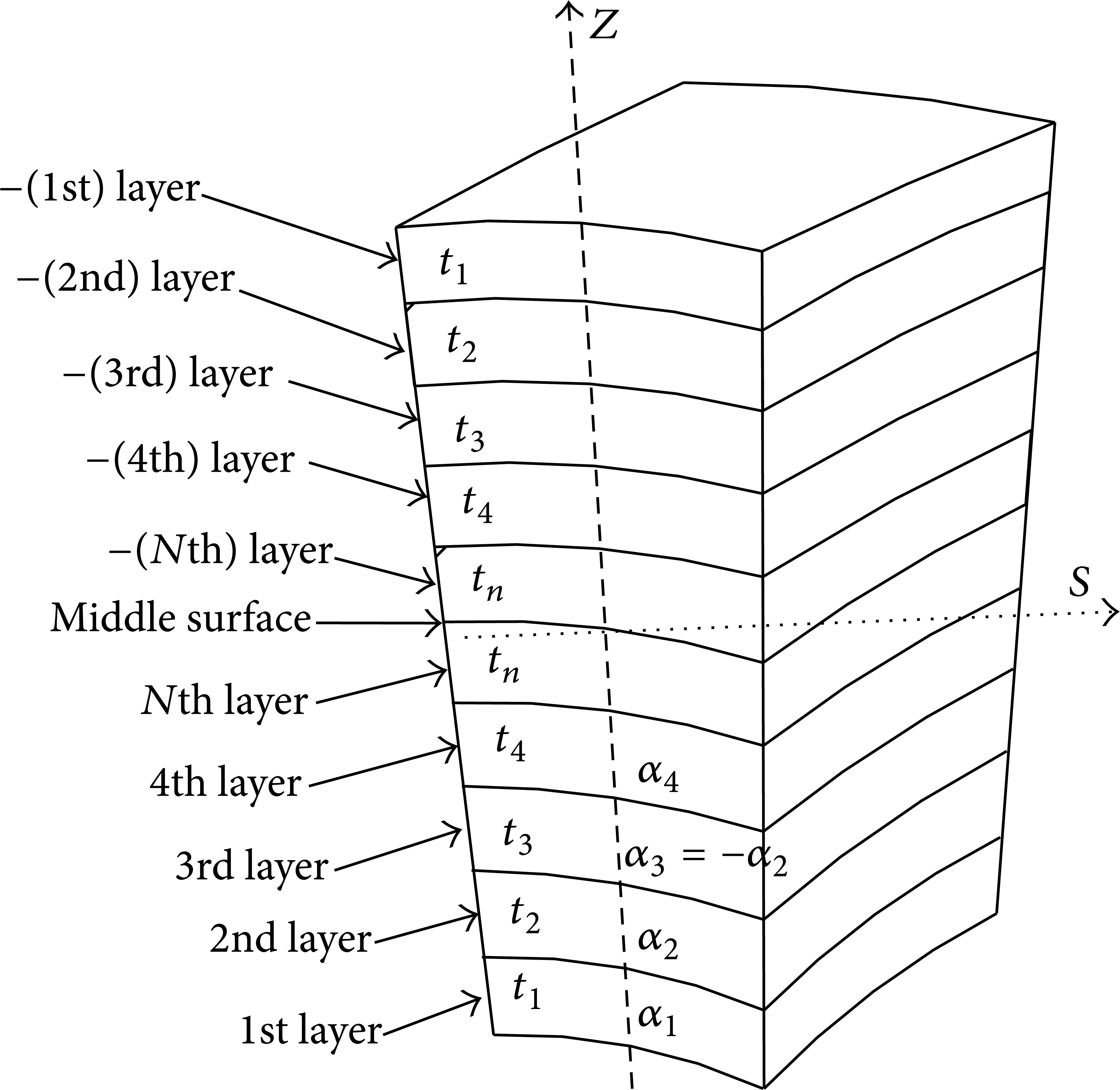
The stacking sequence of the cross section of the shell.
3. Material Property Requirements
The materials for underwater pressure vessels must not only be capable of withstanding very high external pressures, but must also have other suitable properties that can withstand the environment [39]. The main materials for the design of submarine pressure hulls are high strength steels, aluminum alloys, titanium alloys, and composites [39]. Substituting composites for the metallic structures has many advantages because of the higher specific stiffness and strength of the composite materials. In this study, composite materials are used due to their superior properties, like strength-to-weight ratio. Also, composite structures offer great flexibility and stiffness in design, allowing change of the material system in many ways like number of fibers and different lay-up conFigurations. The model is assumed to be constructed from T700/epoxy composites to model the laminates which have high stiffness and strength. The material property and the strength parameters of T700/3234 epoxy are given in Table 1 [22, 23].

4. First-Ply Failure of Angle-Ply Laminate
It is important to note that laminate composites fail in a progressive manner which initiates from the weakest lamina of the laminate and the corresponding load is termed as the first-ply failure load. Failure modes of a composite lamina are dependent on the applied load. If a lamina is subjected to tensile stresses, then its failure modes could be fiber breakage, transverse matrix cracking in the plane of the lamina, or interfiber shear failure of the matrix. In case of compressive stresses, the failure modes could be fiber buckling which dominates failure of the lamina along the fiber direction and matrix crushing which leads to the failure of the composite matrix. All these failure modes can be identified through maximum stress and maximum strain failure theories. In this study, the first-ply failure criterion of angle-ply laminate is considered to be the first strength constraint on the present optimization design problem. The Tsai-Wu failure criterion is employed to assess the capacity of angle-ply laminate of multilayer elliptical pressure hull to withstand overstressing failure. Additionally, a first-ply failure strength load factor (FI) is introduced to identify the characteristics of the first-ply failure of the angle-ply laminate.
The Tsai-Wu failure criterion is the most generalized criterion since it distinguishes between the compressive and tensile strength of a lamina and can be written as the following expanded form [40]:

where the symbols σ1 and σ2 are the stresses in the longitudinal and transverse fiber directions, respectively, and σ6 is the in-plane shear stress. The expressions for the coefficients F11,F22,F66,F1,F2, and F12 are given by
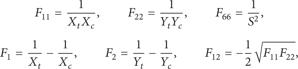
where X t and X c are the longitudinal tensile and compressive strengths, respectively, Y t and Y c are those in the transverse direction, and S is the in-plane shear strength. The Tsai-Wu failure criterion is used for the failure prediction in a ply, and the Tsai-Wu failure function must be lower than 1.0 for the whole model. Accordingly, failure occurs when the above function reaches or exceeds the value 1. Moreover, the following condition must be satisfied to ensure that the angle-ply laminate does not exhibit first-ply failure:

5. Optimization Methodology of Composite Elliptical Pressure Hull
The optimal design problem of composite elliptical submersible pressure hull under hydrostatic pressure is to minimize the buoyancy factor of the submersible pressure hull. Under constraints on both the failure and buckling strength of the hull shell, according to the design requirements. Buckling and failure loads have to be considered in the optimal structural design of the composite elliptical submersible pressure hull under hydrostatic pressure because the buckling load can change according to geometric conditions and stacking sequence while local failure can occur even before buckling. Consequently, the structure's resistance to failure and buckling can be improved by changing the effective modulus or strength by choosing the appropriate materials and lay-up sequence. Therefore, an optimized stacking sequence for the composite elliptical submersible pressure hull is needed. The failure strength is based on the Tsai-Wu failure criterion. The hull buckling failure strength is based on the buckling strength factor (λ) which is the ratio between critical buckling load (Pcr) and actual operating load (P) of the hull shell; it must be greater than one. There are many algorithms and software for implementing the structural optimization [41].
Figure 5 shows the optimization procedure for elliptical submersible pressure hull. The optimization model of the design includes design variables, objective function, and design constraints. The optimization design is described as follows.
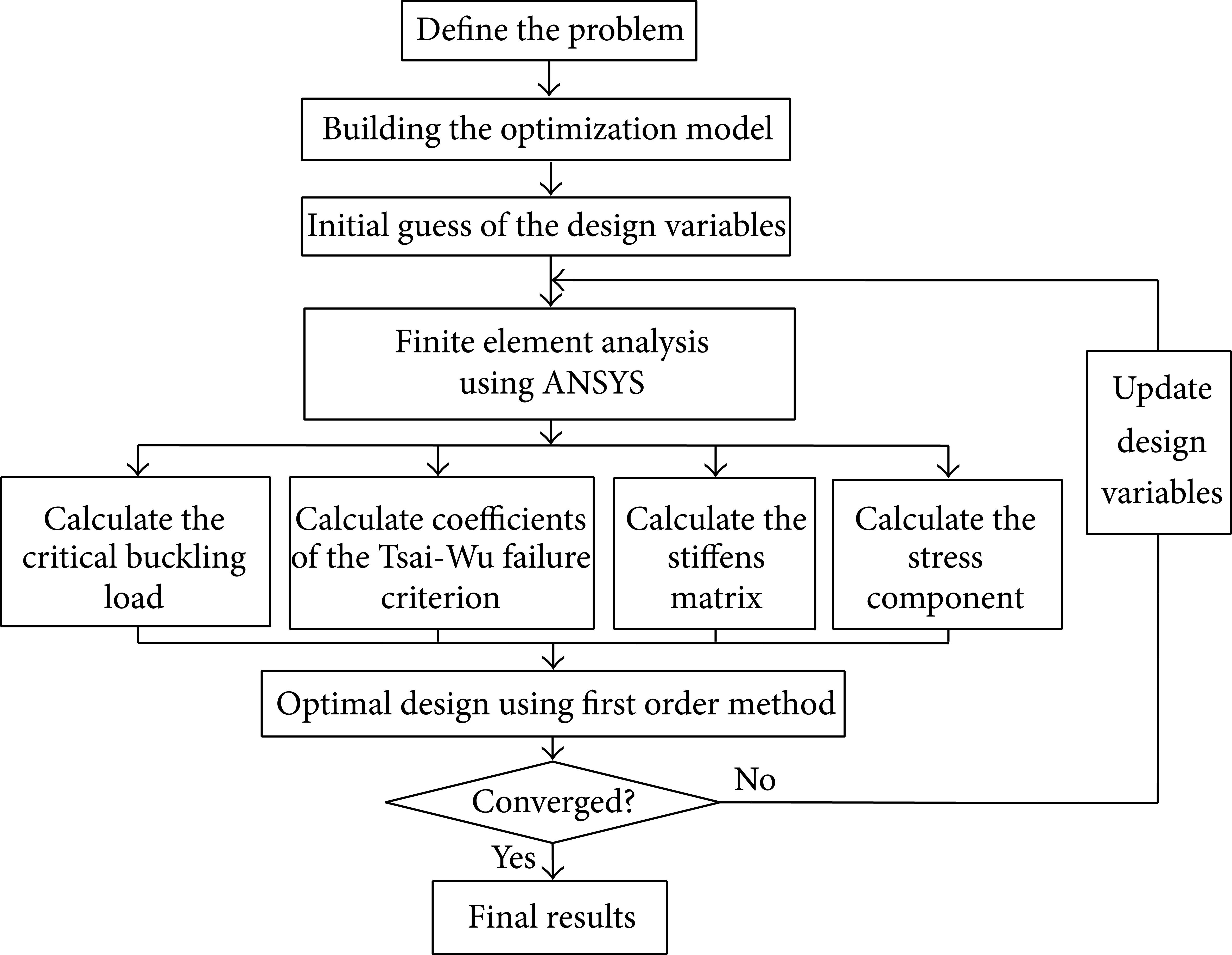
Flow chart of optimal design procedure.
5.1. Design Variables
The radii of the ellipse of the elliptical submersible pressure hull (the major diameter (Dmajor) and the minor diameter (Dminor)), the stringers dimensions (W11,W21,W12, and W22), the orientation angle of the fiber direction for every layer (α1,α2,α3, and α4), the thickness of each layer (t1,t2,t3, and t4), and the operating depth (H) as a state variable are considered for the optimal design problem.
5.2. Objective Function
The optimal design problem involves determining the best geometrical configuration for minimizing the buoyancy factor. Buoyancy factor is used to compensate loss of weight due to immersion in water. Buoyancy is the upward force that keeps things afloat. The net upward buoyancy force equals the amount of the weight of fluid displaced by the body volume. This force will make objects lighter when it immerses in fluid. The objective in the design of the elliptical submersible pressure hull is to minimize the buoyancy factor, which is the common basis for evaluating the structural efficiencies of the various hulls. The objective function is stated as follows:

5.3. Design Constraints
The minimum buoyancy factor design problem of the composite elliptical submersible pressure hull under hydrostatic pressure treated here has two behavior constraints that control the failure modes and side constraints which specify the permissible range of design variables to specify spatial and human requirements. Such constraints are presented as follows.
5.3.1. Behavior Constraints
In order to ensure the optimum structural design on the elliptical submersible pressure hull to reach the maximum operating depth, the material and buckling strength constraints must be satisfied and are defined as follows.
Material Strength Constraint. In order to avoid materials failure, the Tsai-Wu failure criterion is used for the failure prediction in a ply, and the Tsai-Wu failure function (FI) must be lower than 1.0 for the whole model. Hence, the strength inequality constraint can be expressed as

where FI is first-ply failure of the angle-ply laminate for each ith layer and n is the number of layers.
Instability Constraint (Buckling Constraint). The minimum critical buckling load (Pcr) must exceed the maximum actual operating loading (P) to ensure the stability of the pressure hull. Therefore, a general instability of elliptical submersible pressure hull is presented as

Operating Depth. In order to reach the maximum operating depth withstanding the applied hydrostatic pressure,
where H and H U represent the operating depth and its upper limit, respectively.
5.3.2. Side Constraints
In addition, corresponding to the choice of the design variables, the following conditions of the dimensioning belong to the group of side constraints in these investigations:

where D i , D i L , and D i U represent the ith elliptical submersible pressure hull diameters and their upper and lower limits, respectively.
For the ring beams and stringers with rectangular cross-section.

where Wi1, Wi2, Wi1 U , Wi1 L , and Wi2 L represent the ith rings beam and stringers cross-section dimensions and their upper and lower limits, respectively. Consider

where t i , t L , and t U represent the ith thickness and the lower and upper bounds imposed on the individual ply thicknesses. Consider

where α i , α L , and α U represent the ith orientation angle of each layer and their upper and lower bounds, respectively. The angles are given in degrees and varied from 1° to 90°.
6. Finite Element Model Simulation
The main requirement of composite elliptical submarine submersible pressure hulls is to resist hydrostatic pressure exerted by water at maximum operating depth to protect personnel and equipment inboard when submerged. When hydrostatic pressure exceeds a critical value, shell buckling may occur to the pressure hull and the angle-ply lamina failure stress exceeds the strength. To understand the mechanical behaviors of composite elliptical submarine submersible pressure hulls and to avoid these failures, the buckling strength, the failure strength, and the maximum deflection are analyzed using FEA software ANSYS. The structure is modeled using SHELL99 (linear layered structural shell element with 8-node, 3-D shell element, with six degrees of freedom at each node). The BEAM189 (six degrees of freedom occur at each node) is used for rings beam and stringers. BEAM189 is a quadratic three-node beam element in 3D [42, 43].
The shell consists of thirty-two layers with stacking sequence
7. Numerical Results and Discussions
Results of the optimization procedures for composite elliptical deep submersible pressure hull are presented and summarized in Table 2 and Figures 6–11. Table 2 indicates the optimal design point and shows that the optimal objective function (buoyancy factor (B.F)) is 0.27023 and the maximum Tsai-Wu failure is 0.98381 which occurs in the bottommost fiber. Also, it is noted that the optimal angle-ply orientations for thirty-two layers are
The results of the optimal design.

Effect of design variables on buoyancy factor.
Effect of design variables on buckling strength.

Displacement distribution for elliptical submersible pressure hull.

Effect of design variables on maximum deflection.

Tsai-Wu failure distribution for elliptical composite submersible pressure hull.

Effect of design variables on Tsai-Wu failure index.
7.1. Effect of Design Variables on Buoyancy Factor
The buoyancy factor is a parameter expressing the efficiency of the structure in terms of its ability to provide for an excess of displacement over that required to support its own weight. 1.0 is seen to be the critical value of the buoyancy factor, where the empty pressure hull is in a condition of neutral buoyancy with zero efficiency with respect to its ability to support other weights. Figure 6 shows that the B.F is directly proportional to each shell thickness (t). The B.F is inversely proportional to the major diameter (Dmajor) and minor diameter (Dminor). In addition, larger t1,t2,t3, and t4 all imply a higher B.F. Also, the B.F will be decrease as Dmajor and Dminor increase.
7.2. Effect of Design Variables on Buckling Strength Factor
Figure 7(a) shows the effect of α upon the buckling strength factor; in case of α1, as it increases the buckling strength factor decreases with small rate until α1 equals 45°. After that the buckling strength factor decreases rapidly until α1 equals 70°. With increasing α1 the buckling strength factor increases again. The α4 has the same trend as α1. In case of α2, as α2 increases the buckling strength factor increases until α2 equals 20°. After that the buckling strength factor decreases as α2 increases. Figure 7(b) shows the effect of Dmajor upon the buckling strength factor. This figure shows that as Dmajor increases the buckling strength factor decreases rapidly. The maximum variation occurs at Dmajor (1.9–2.1 m). After that, as Dmajor increases buckling strength factor decreases with minimum variation. In order to avert the failure, the Dmajor can be appropriately chosen to be less than 2.2 m.
Figure 7(c) shows the effect of Dminor upon the buckling strength factor, which shows that as Dminor increases the buckling strength factor increases and reaches to the maximum value when Dminor is nearly equal to Dminor. In order to avert the failure, the Dminor can be appropriately chosen to be more than 1.7 m. Figure 7(d) shows the effect of H upon the buckling strength factor. This curve shows that as H increases the buckling strength factor decreases with relatively high slope until H equals 4000 m; after that the slope is decreasing.
Figure 7(e) shows the effect of layer thickness upon the buckling strength factor. It can be seen that as t1 and t4 increase the buckling strength factor decreases but t1 has more effect on buckling strength factor than t4 which indicates that the geometric effects have a great influence upon the stability. As t2 and t3 increase, the buckling strength factor increases and the maximum variation occurs when the range of layer thickness is between 0.0005 and 0.002 m. Also, the figure illustrates that t2 and t3 heavily influence the buckling strength factor.
7.3. Effect of Design Variables on Maximum Deflection Value
The displacement distributions in both X and Y directions for elliptical submersible pressure hull are shown in Figure 8. The maximum magnitude of the displacement occurs at centroid regions of the submarine in Y direction as shown in Figure 8(a). In case of X direction, the maximum magnitude of the displacement occurs at the right of main part of the submarine as shown in Figure 8(b).
Figure 9(a) shows the effect of α on maximum deflection value; for α1, the maximum deflection occurs when α1 equals 0°. With increasing α1, the maximum deflection value decreases and reaches the minimum value when α1 equals 90°. The orientation of fiber direction in layer 4 (α4) has the same trend as α1 but its effect upon the maximum deflection value is less than α1. For the orientation of fiber direction in layer 2 (α2) and layer 3 (− α2) as α2 increases the maximum deflection value is nearly constant until α2 equals 38°. After that, as α2 increases the maximum deflection value increases and reaches the maximum value when α2 equals 90°.
Figures 9(b) and 9(d) show the effect of Dmajor and H upon the maximum deflection value. The curve illustrates that Dmajor and H are directly proportional to maximum deflection value. The influence of Dmajor upon deflection value is greater than the operating depth. Figures 9(c) and 9(e) show that the maximum deflection value is inversely proportional to each shell thickness (t) and minor diameter (Dminor). Also, t1 has the largest effect on the maximum deflection value and t3 has the minimum effect on the maximum deflection value.
7.4. Effect of Design Variables on Maximum Tsai-Wu Failure
The Tsai-Wu failure distributions for elliptical composite submersible pressure hull are shown in Figure 10. The maximum Tsai-Wu failure occurs at layer (1) and layer (4), which reveals that the failure will be initiated first in the bottommost lamina at the middle of the sides of the plates near the stringers. Figure 11(a) shows the effect of α1 upon the Tsai-Wu failure; the maximum Tsai-Wu failure occurs when α1 equals 0° for all layers. The maximum value of Tsai-Wu failure occurs at layer (4). As α1 increases the maximum Tsai-Wu failure decreases until α1 equals 40°. The maximum Tsai-Wu failure for layer (1) decreases and reaches the minimum value but the failure still exists in layers 2, 3, and 4. With increasing α1, the maximum Tsai-Wu failure decreases until α1 equals 85.5°; at this value there is no failure and the maximum Tsai-Wu failure for all layers will be less than one.
Figure 11(b) shows the effects of α2 upon Tsai-Wu failure and it is observed that all the layers nearly have the same trend. The minimum Tsai-Wu failure occurs when α2 equals 0°. As α2 increases, the changes in the maximum Tsai-Wu failure are too small until α2 equals 40°. After that, as α2 increases, the maximum Tsai-Wu failure increases and reaches the maximum value when α2 equals 90°. Figure 11(c) shows the effects of α4 upon Tsai-Wu failure; it shows that α4 has the same effect on the maximum Tsai-Wu failure as α1. Figure 11(d) shows the effect of Dmajor upon the maximum Tsai-Wu failure, which indicates that as Dmajor increases the Tsai-Wu failure increases. To avert the failure, the Dmajor can be appropriately chosen to be less than 2.05 m.
Figure 11(e) shows the effect of Dminor upon Tsai-Wu failure which indicates that as Dminor increases the Tsai-Wu failure decreases. In order to avert the failure, the Dminor can be appropriately chosen to be not less than 1.93 m. Figure 11(f) presents the effect of H upon the maximum Tsai-Wu failure of the elliptical composite submersible pressure hull. The curve shows that the maximum Tsai-Wu failure is directly proportional to operating depth. In order to avert the failure, the maximum operating depth must be less than 4200 m. Figure 11(g) shows the effect of t1 upon the maximum Tsai-Wu failure. The curve shows that the maximum Tsai-Wu failure is inversely proportional to t1.
Figure 11(j) has the same trend as Figure 11(g) but t1 has a greater influence on the value of the maximum Tsai-Wu failure than t4. In order to avert the failure, t1 and t4 must be more than 1.79e–3m and 1.08E–03m, respectively. Figure 11(h) presents the effect of t2 upon the maximum Tsai-Wu failure. It can be observed that the maximum Tsai-Wu failure is inversely proportional to t2. Figure 11(i) has the same trend as Figure 11(h) and shows that t2 has a greater influence on the value of the maximum Tsai-Wu failure than t3. In order to avert the failure, t2 and t3 must be more than 1.66e–3m and 0.52E–03m, respectively.
8. Conclusions
This paper presents the optimum design of elliptical composite submersible pressure hull under hydrostatic pressure to minimize the buoyancy factor of the pressure hull. Sensitivity analyses were performed to study the effects of the design variables on the optimal structural strength design. The minimum buoyancy factor provides a valuable reference for the submarine pressure hull design so as to increase the payload and the performance with respect to controlling the submarine. The Tsai-Wu failure criteria predict efficiently the ply failure of elliptical composite submersible pressure hull under hydrostatic pressure. Resistance to in-plane forces rather than shell buckling is the critical design consideration at extreme operational depths in this case. It implies that a high material strength is important for deep-diving pressure hulls. To achieve high values of the material failure loads, the bottommost lamina of the elliptical composite submersible pressure hull should have the fibers oriented nearly in the circumferential direction. The design variables (Dmajor,Dminor,t2, and t3) heavily influence buoyancy factor. The design variables (α,H,Dmajor,Dminor,t2, and t3) heavily influence the buckling strength factor. The design variables (Dmajor and Dminor) heavily influence the maximum deflection value; the design variables (H,α1,α4, and t) have a moderate influence upon maximum deflection value. The design variables (α,Dmajor,Dminor, and t) heavily influence the Tsai-Wu failure. The results can serve as a valuable reference for designers of underwater vehicles.
Conflict of Interests
The authors declare that there is no conflict of interests regarding the publication of this paper.
Footnotes
Authors’ Contribution
Professor Tong Lili and Dr. Mahmoud Helal have the same contribution.