
Abstract
In the past decades, researchers have deeply studied pathological and nonpathological gait to understand the human ankle function during walking. These efforts resulted in the development of new lower limb prosthetic devices aiming at raising the 3C-level (control, comfort, and cosmetics) of amputees. Thanks to the technological advances in engineering and mechatronics, challenges in the field of prosthetics have become an important source of interest for roboticists. Currently, most of the bionic feet are still on a research level but show promising results and a preview of tomorrow's commercial prosthetic devices. In this paper, the authors present the current state-of-the-art and the latest advances in propulsive bionic feet with its actuation principles. The context of this review study is outlined followed by a brief description of the basics in human biomechanics and criteria for new prosthetic designs. A new categorization based on the actuation principle of propulsive ankle-foot prostheses is proposed. Based on simulations, the general principles and benefits of each actuation method are explained. The corresponding latest advances in propulsive bionic feet are presented together with their main characteristics and scientific outcomes. The authors also propose to the reader a comparison analysis of the presented devices with a discussion of the general tendencies in new prosthetic feet.
1. Introduction
A transtibial (TT) amputation is often the treatment of choice for an unreconstructable or a functionally unsatisfactory limb. Possible reasons are severe trauma, peripheral vascular disease (PVD), tumors, infections, or congenital limb deficiency [1]. From the medical literature it is known that below-knee amputations are among the most frequently performed major limb removals and one of the oldest surgically performed procedures [2]. To replace the missing limb, many prosthetic feet have been developed in the past to, at least, restore basic functional mobility. As a matter of fact, the surgery must be performed well to ensure that the patient is able to wear a prosthesis comfortably. The selection of this prosthesis will be strongly dependent on the needs and abilities of the amputee. In general, the higher the level of a lower-limb amputation, the greater the energy expenditure that is required for walking [3]. And of course, the characteristics of the prosthesis itself directly influence the gait of the patient. Moreover, gait analyses have shown that, when walking, a sound ankle produces substantially more work than any other joint of the lower limbs [4, 5]. Winter [6] mentioned that the ankle joint muscles produce on average 540% more work than they store during walking. Therefore, the replacement of power generation at the ankle is one of the biggest challenges in replicating nonpathological gait by means of prosthetics [7].
Over the past decades, many researchers have studied human gait (pathological and nonpathological) in terms of kinematics, dynamics, and energy expenditure in view of developing new prosthetic devices that aim at raising the 3C-level (control, comfort, and cosmetics) of a patient by putting effort in mimicking the characteristics of an intact limb. Since the last 10 years, these challenges tend to overlap in the field of mechatronics and robotics. This evolution was possible thanks to the technological improvements in mechanical engineering, computer aided design and simulation software, cheap and miniaturized microcontroller technology, and the recent development of several new types of (compliant) actuators such as pneumatic artificial muscles (PAM) [8, 9], series elastic actuators (SEA) [10], variable stiffness actuators (VSA) [11], and explosive elastic actuators [12].
An overview of the preferred actuator technology in rehabilitation robotics can be found in [13, 14]. For a complete state-of-the-art overview on compliant actuation, the authors refer to [11, 15].
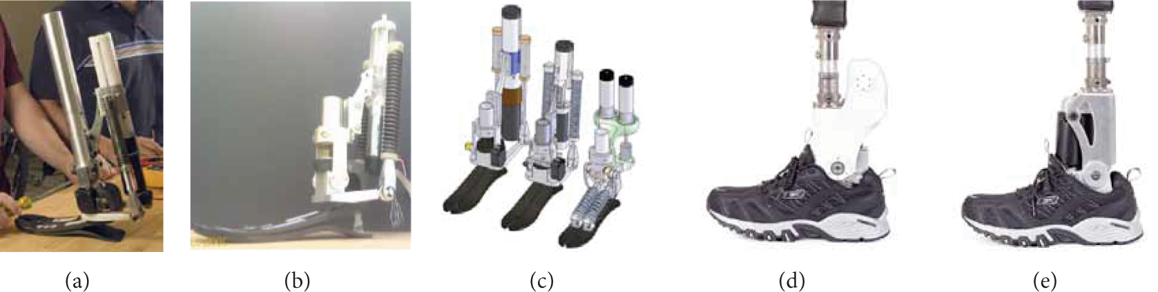
Until the 80s, the focus on the design of prosthetic feet was on trying to restore basic walking and enabling the amputee to fulfill basic tasks. The prostheses evolved to the so-called conventional feet (CF), which were still very basic but allowed future prostheses to focus on weight and functionality. Driven by the desire of amputees to walk more naturally, to reduce metabolic cost and even in some cases practicing sports, prosthetic feet were significantly improved over the last decades. Numerous prosthetic feet are currently on the market for individuals with a transtibial amputation; each device aimed at raising the aforementioned 3C-level with slightly different characteristics. In general, today's prosthetic feet can be classified into three main categories: conventional feet (CF), energy-storing-and-returning (ESR) feet, and the so-called bionic feet. Figure 1 gives an overview of the categorization of today's prosthetic feet. As depicted, ESR feet can be subdivided into the early ESR, advanced ESR, and articulated ESR, while bionic feet can be further divided into stabilizing and propulsive devices. Articulated ESR feet typically make use of electronics and small servomotors to engage or disengage locking mechanisms. Although these devices are highly elaborated mechatronical systems, they fall out of the state of the art in propulsive bionic, feet since they do not make use of external mechanical power generation to provide their wearer with active stabilization or push-off properties. Comprised in the category of articulated ESR feet are Brackx et al.'s AMP-Foot 1.0 and 1.1 [16], Collins and Kuo's CESR foot [17], and Mitchell et al. ankle-foot prosthesis with delayed plantarflexion [18], to name a few. A complete state-of-the-art study of CF and ESR feet can be found in [19].
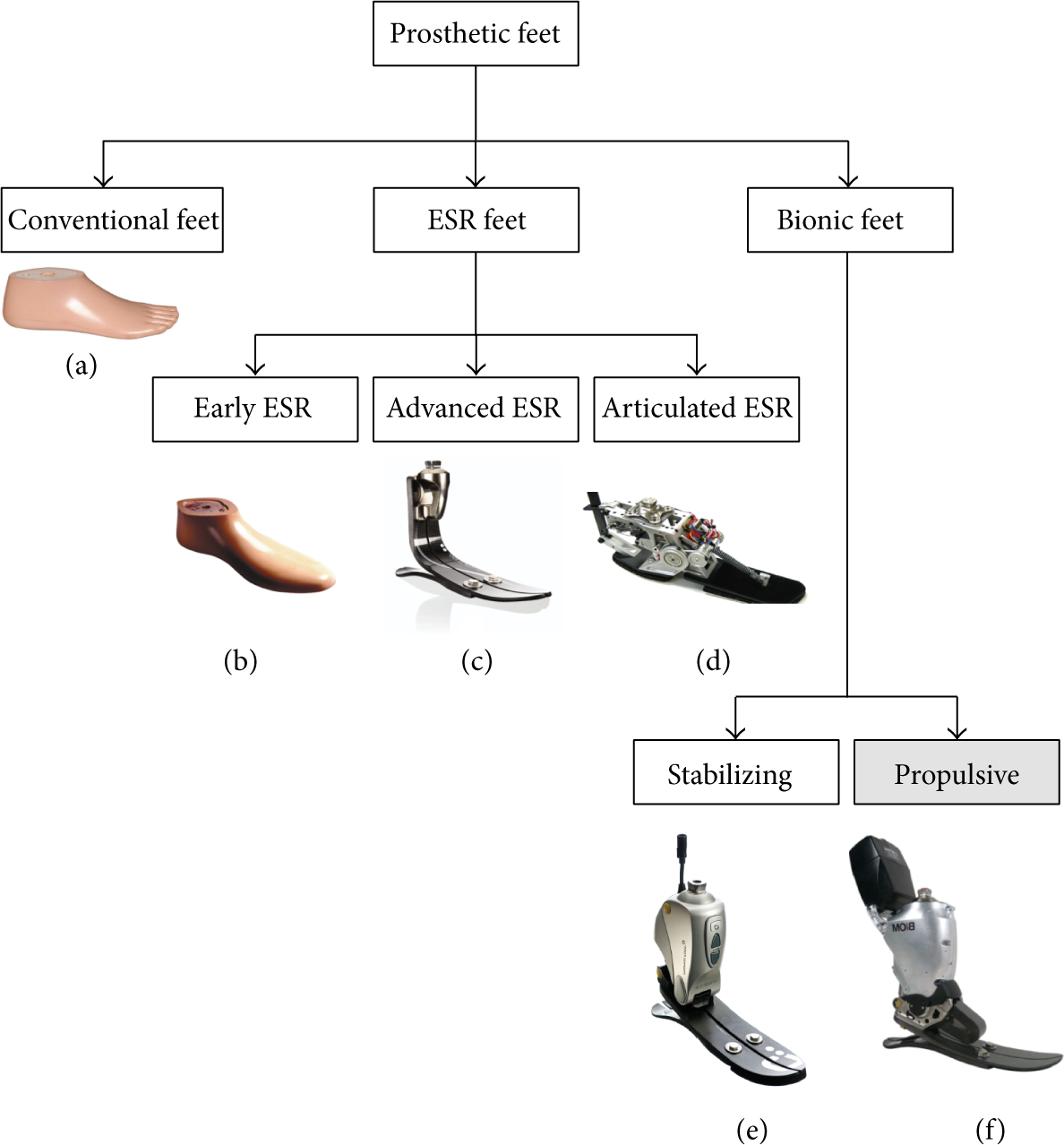
Categorization of today's prosthetic feet with as example (a) the SACH foot, (b) the SAFE foot, (c) Össur's Flex-Foot, (d) the CESR foot [17], (e) Össur's Proprio Foot, and (f) iWalk's Powerfoot BiOM. This paper is focussed on propulsive bionic feet. For a complete state-of-the-art study of conventional feet, ESR feet, and stabilizing bionic feet, the authors refer to [19].
To avoid misunderstandings, a bionic foot is defined as a mechanical device with one or more active components, used either for stabilization of the foot or to provide active push-off properties (i.e., propulsive bionic feet), that is, worn by an individual with TT amputation.
Most of today's commercialized powered transtibial prostheses use actuation to provide stabilization of the ankle-foot complex. Examples are the Motion and Raize Foot (Fillauer), the Elan foot (Endolite), and the Proprio Foot (Össur). This kind of prostheses uses either hydraulic or electric actuation to provide natural ankle kinematics and intelligent terrain adaptation but does not provide more power to the individual than the one stored during gait. This paper will not focus on this type of prosthetic devices either. Existing stabilizing bionic feet are presented in [19].
The last few years have seen impressive advancements in the development of new generation powered propulsive prostheses with the potential to improve considerably amputee physical shortcomings and to overcome the psychological stigma. Therefore, with this paper the authors propose a review study of the latest advances in propulsive bionic feet including a new categorization based on their actuation method, working principle, degrees of freedom, and other relevant parameters. It should be noted that, next to the mechanical challenges, important issues like intelligent control and human-machine interface are gaining increasing popularity in the research field too [20–22]. However, this falls out of the scope of this paper. For a review about powered prostheses focusing on control methods, the authors refer to [23].
In Section 2 the basics of walking biomechanics are briefly highlighted in order to fix the context of TT prostheses design. In Section 3 the authors present the advances in propulsive powered TT prosthesis based on the new aforementioned categorization. The implication of the different actuation methods on the torque and power requirements of the devices will also be presented [24–27] and the scientific outcomes of each (propulsive) bionic foot will be exposed when available. A comparison analysis is proposed in Section 4. Conclusions in Section 5 will close the paper.
2. Prosthetic Feet: Background
In this section, the authors present a summary on the biomechanics of the ankle-foot complex together with its implication on the development of new prosthetic feet. For more detailed information on biomechanical definitions and measures, the authors refer to the corresponding literature [6, 28–32].
Hansen et al. [29] have discussed stiffness characteristics of the human ankle, together with the evolution of intrinsic stiffness of the ankle with different walking speeds. Similar plots have been determined by Günther and Blickhan [33]. By understanding these human ankle characteristics, mimicking total human ankle behavior has become the primary challenge, rather than just assuring energy return at specific instances during gait.
According to systematic gait analysis from Winter [6], a subject walking at normal cadence produces a peak torque at the ankle joint of approximately 1.6 Nm/kg in a very small amount of time (±0.2 s for a walking rate of 1 step/s), consuming hereby on average 0.35 J/kg of mechanical energy per step. In accordance the generated power at push-off reaches peak values of approximately 3.5 to 4.5 W/kg. Considering a 75 kg subject a maximum torque output of approximately 120 Nm is required with a power output between 250 and 350 W as can be seen in Figures 2(a) and 2(b). These approximate values are generally taken as a criterion for the development of the so-called propulsive devices. Therefore, throughout the following sections these data will be used as a reference.

(a) Characteristics of an ankle joint for a 75 kg subject walking at normal cadence: ankle angle, torque, and power versus percentage of stride during one step. Data taken from [6]. (b) Torque-angle characteristics of an intact ankle joint for a 75 kg subject walking at normal cadence. Data taken from [6]. The main phases of gait are highlighted as initial contact (IC), foot flat (FF), heel off (HO), and toe off (TO).
3. Advances in Propulsive Bionic Feet
In this section, a new categorization shown in Figure 3 is proposed with the focus on propulsive bionic feet. Based on the actuation principle a first distinction can be made between ankle-foot prostheses powered with stiff or compliant actuation. The compliant actuators can further be divided into pneumatic actuators with the pneumatic artificial muscles and electric actuators comprising the series elastic actuator (SEA) [10], the series elastic actuator with parallel spring (SEAPS), the variable stiffness actuator (VSA) [11], the variable stiffness actuator with parallel spring (VSAPS), and the explosive elastic actuator (EEA) [12]. The virtues and flaws of each of these actuation methods will be shortly discussed. The aim is to understand the general principles of each actuator, without going into the details of a specific actuation scheme of a specific prosthesis. An overview table summarizes the actuator's energetic analysis in Section 4 (Table 1). As mentioned before, Winter's data [6] is used as a reference for these analyses. This means that the calculations and possible optimizations will be as such that the output of any actuation scheme discussed hereafter will equal the kinematics of a sound ankle-foot complex. In addition every existing propulsive bionic foot will be presented in its corresponding category highlighting its characteristics and scientific outcomes when available. A detailed overview and comparison of propulsive bionic feet is given in Section 4 (Table 2).
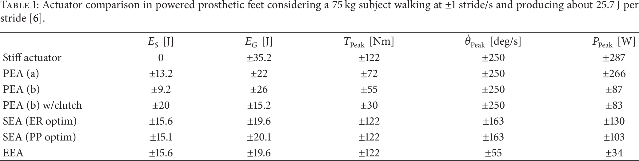
Actuator comparison in powered prosthetic feet considering a 75 kg subject walking at ±1 stride/s and producing about 25.7 J per stride [6].
Overview of today's propulsive bionic feet as defined in Section 1 including their main characteristics.


Categorization of propulsive ankle-foot prostheses based on their actuation method.
3.1. Stiff Actuation
In this context, a stiff actuator is considered to be an actuator that is unable to store energy by elastic deformation (e.g., electric motor). According to Winter [6], considering a 75 kg subject, a maximum torque output of approximately 122 Nm is needed. Using, for example, an electric motor implies a peak power output at push-off of approximately 287 W (without losses) and a peak speed of 250 deg/s. Considering an optimistic motor-gearbox efficiency of 50 to 60% gives a minimum power rating estimation of 400 to 600 W. The mechanical energy requirements of the actuator for a sound human ankle (shown in Table 1) can be calculated by integrating the power curve shown in Figure 4. When actuating an ankle prosthesis with a stiff actuator, both positive and negative energy have to be delivered, which means a total energy of 35.2 J (barring the actuator losses).

Characteristics of the human ankle joint: ankle power versus percentage of stride and torque-angle characteristics of one step. From initial contact (IC) to mid stance (MS) the power curve is mainly negative, while during push-off a large positive power peak is required. During the swing phase, almost no mechanical power is delivered. When using a stiff actuator, the negative and positive powers have to be provided.
At Carnegie Mellon University, Pittsburgh (United States), Caputo and Collins [34, 35] developed an experimental, tethered prosthesis testbed able to provide powered push-off work to subjects walking on a treadmill to conduct controlled experiments for understanding relationships between prosthesis control parameters and performance (Figure 5). The system has the capabilities to provide much more power and control than other robotic prostheses so that a wide variety of these parameters can be tested and their effect measured. This is the hope of providing data for designers of future mobile prosthesis seeking optimal control strategies. The device has a single degree of freedom and is actuated via a flexible Bowden-cable transmission by a motor using a series-elastic torque control scheme. The lightweight prosthesis (approx. 1 kg) is powered by a 1.61 kW servomotor (Baldor Electric Co.) and controlled with a real-time controller (DS1103, dSPACE Inc.), providing hereby up to 232 Nm of push-off torque and a range of motion of 14 deg dorsiflexion to 29 deg plantarflexion to the wearer. Benchtop tests revealed the −3 dB gain bandwidth to be 11.6 Hz for a 75 Nm sinusoidal torque input [36, 37]. As a matter of fact, this type of technology presents an interesting experiment-centered approach to the development of ankle-foot prostheses, in which design requirements and tradeoffs are established prior to product design tasks such as miniaturization.
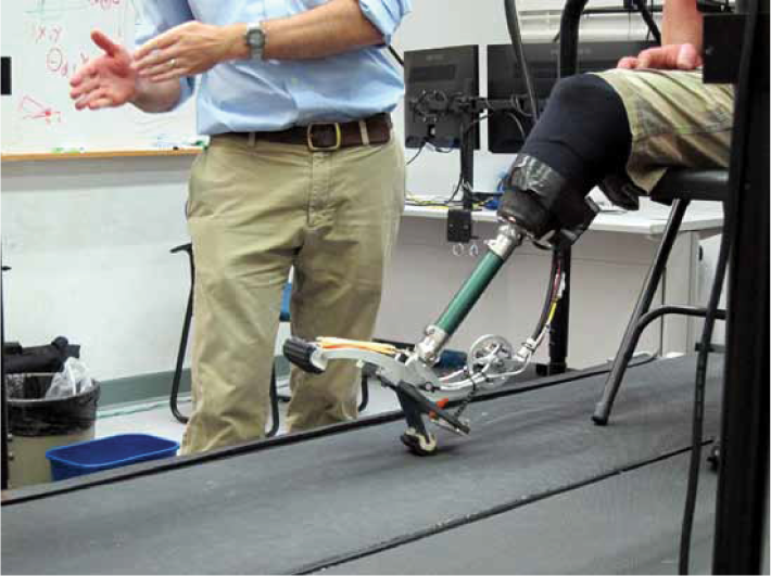
Tethered prosthesis testbed developed at Carnegie Mellon University, Pittsburgh, USA.
However, it should be noted that placing a parallel spring to a stiff actuator (hereby forming the so-called parallel elastic actuator (PEA)) has the potential to lower the actuator's torque compared to a regular stiff actuator, but not its speed. As such, the PEA is still a stiff actuator. Although no prosthetic device has been developed using this actuation method, the consequences of using a PEA are briefly discussed. In Figure 6, the effect on the ankle torque-angle characteristic of 2 different parallel springs in a PEA is depicted.
PEA (a): the parallel spring has its zero-torque angle close to IC and tangent to the torque angle curve. The stiffness is 8.3 Nm/deg and the zero-torque angle is 0 deg.
PEA (b): the parallel spring is positioned to represent the average slope of the torque-angle curve. Its stiffness is 5.1 Nm/deg and the zero-torque angle is −10 deg.

Effect on the ankle torque-angle characteristic of 2 different parallel springs in a PEA. (a) The parallel spring has its zero-torque angle close to IC and tangent to the torque angle curve. The stiffness is 8.3 Nm/deg and the zero-torque angle is 0 deg. (b) The parallel spring is positioned in the “heart” of the torque-angle characteristic. Its stiffness is 5.1 Nm/deg and the zero-torque angle is −10 deg.
From Figure 6 it is clear that the actuator torque of the PEA can be significantly lowered compared to the previous situation. It is important to note that the actuator torque and power of the PEA are nonzero from TO to FF, as indicated by the gray regions in Figure 7.

PEA's torque and power characteristics compared to the reference data [6]. It can be seen that the actuator torque is significantly reduced by using a parallel spring (in both configurations). On the power characteristics one can see that the actuator peak power is reduced (blue curve) at push-off but that the swing phase requires more energy than normal. The shaded area (gray) represents a clutchable region between toe-off (TO) and foot-flat (FF).
Considering PEA (a), it can be seen that the peak power is approximately 266 W and its peak torque reduced to 72 Nm while, as expected, the peak speed remains 250 deg/s. Considering PEA (b), the peak power is reduced to approximately 87 W and its peak torque to 55 Nm, while, as expected, the peak speed remains 250 deg/s. Both the mechanical energy requirements of the actuator in the PEA (a) and (b), calculated by integrating the corresponding power curve in Figure 7, are presented in Section 4 (see Table 1). Although PEA (b) seems to show a better reduction of the peak power and peak torque during walking, the parallel spring has a dramatic influence in the phase between toe-off (TO) and foot-flat (FF) where normally almost no torque and power has to be delivered. However, equipped with a well-tuned clutch, the influence of the spring during the swing phase might be canceled, diminishing hereby the energy requirements drastically. Assuming thatsuch a clutch mechanism is feasible the peak power of the PEA would be reduced to 83 W and its peak power to 30 Nm, while of course its peak speed remains the same. However, since such a clutch mechanism has not been developed (yet) and because placing a stiff actuator in an untethered prosthesis is currently unrealistic in terms of weight and size, researchers have opted for compliant actuation in electrically stand-alone devices reducing hereby the power requirements of the actuator (but not its required torque output) [24] as will be seen in the next section.
3.2. Compliant Actuation
As opposed to a stiff actuator, a compliant actuator will be able to store energy by elastic deformation. Its equilibrium position is defined as the position of the actuator where zero force or zero torque is generated. Since compliance is the opposite of stiffness, both terms are used to describe the compliant or nonstiff behavior of an actuator. To describe an actuator with a variable stiffness, the term adjustable compliance can be used and also variable compliance, adjustable stiffness, and controllable stiffness [38]. These examples are given to show that there is not a standard terminology to describe these types of actuators. They belong in the category of the variable impedance actuators (VIA) [11].
As mentioned before, a distinction can be made based on the energy source of the used compliant actuator differentiating hereby pneumatically and electrically actuated propulsive devices. It is interesting to mention that the reason why researchers have opted for one or the other is generally very different. Pneumatic actuators originally were chosen because their design and setup correspond best to the musculoskeletal structure and properties of human beings. This explains also why these actuators are generally called pneumatic artificial muscles (PAM) [39]. On the contrary, using compliant actuation in electrically driven stand-alone devices has the advantage of reducing the power requirements of the drive resulting in a smaller, less heavy and cheaper actuation setup [24].
3.2.1. Pneumatically Actuated Propulsive Devices
Pneumatic actuators are mostly known as “antagonistically controlled stiffness” actuators because two actuators with nonadaptable compliance and nonlinear force displacement characteristics are coupled antagonistically. By controlling both actuators, the compliance and equilibrium position can be set [40].
At the University of Washington (United States) Klute et al. [41, 46, 47] have designed an artificial muscle-tendon actuator to power a below-knee prosthesis. To meet the performance requirements of an artificial triceps surae and Achilles tendon, an artificial muscle, consisting of two flexible pneumatic actuators in parallel with a hydraulic damper, and placed in series with a bilinear, two-spring implementation of an artificial tendon, was built into the ankle-foot prosthesis. Based on simulation results, the powered prosthesis was expected to provide a 110 Nm torque output with 30 deg range of ankle motion. To the author's knowledge, the only published material concerning this pneumatically actuated prosthesis consists of a photograph shown in Figure 8(a).

State of the art in pneumatically actuated ankle prostheses. From left to right: Washington's variable stiffness prosthetic ankle [41]; pleated pneumatic artificial muscle (PPAM) actuation in the Vrije Unversiteit Brussel's prosthesis [9]; Alabama and Vanderbilt university ankle-foot complex using a rocket-like propellant [42]; sleeve muscle actuation prosthesis developed by Zheng and Shen [43]; powered transfemoral prosthesis from Vanderbilt University [44, 45].
The Vrije Universiteit Brussel (Belgium) developed within the Robotics & Multibody Mechanics Research Group the pleated pneumatic artificial muscle (PPAM) [9], originally intended to be used in bipedal walking robots. It is a lightweight, air-powered, muscle-like actuator consisting of a pleated airtight membrane. Its advantage compared to other artificial muscle comes from the unfolding of the pleated membrane. Because of this there is virtually no threshold pressure, hysteresis is reduced when compared to other types of muscles, and contractions of over 40% of the initial length are possible. Within the IPAM (intelligent prosthesis using artificial muscles) Project [48], a TT prosthesis using pleated pneumatic artificial muscles (Figure 8(b)) was developed to demonstrate the importance of push-off during gait [48]. The prototype is equipped with three PPAMs: one is placed anteriorly and two are placed posteriorly and work in parallel. The actuator easily produces a torque output of 200 Nm with a muscle pressure of only 3 bar. In addition, two posterior muscles in parallel make it possible to establish motion in the frontal plane. Successful walking experiments with an individual with TT amputation wearing the prosthesis prototype were conducted by Versluys et al. [49].
Sup et al. [44, 45] at Vanderbilt University (United States) have developed a (tethered) powered transfemoral prosthesis using knee and ankle pneumatic actuation which serves as laboratory testbed (Figure 8(e)). The work of Sup et al. is mentioned in the state of the art because the prototype consists of both an articulated knee and ankle joint. The device is powered by two pneumatic cylinders to investigate different control strategies [50]. Further research with this prototype led to the development of an electrically powered transtibial [51] and transfemoral [52, 53] prosthesis which will be discussed in Section 3.2.2.
Researchers from University of Alabama (United States), Vanderbilt University (United States), and the Georgia Institute of Technology (United States) have teamed up to develop a pneumatic ankle prosthesis that is powered by rocket-like propellant. The technology seems to have had its roots at Vanderbilt, in the team of Goldfarb et al., and consists of a miniaturized monopropellant rocket motor system as used by space shuttles for maneuvering in orbit. The monopropellant works as an energy-storing medium and decomposes upon contact with certain catalysts. According to Shen et al., the use of this fuel allows for a lightweight prosthesis that stores enough energy to operate for daily use. Although a transhumeral prosthetic device [42] has already been built using this technology, the only published material that is available, to the author's knowledge, on lower-limb prosthetics is a picture shown in Figure 8(c).
Zheng and Shen [43] developed a concept of a new sleeve muscle actuator for use in a transtibial prosthesis. The so-called sleeve muscle actuator incorporates a cylindrical insert to the center of the pneumatic muscle, which eliminates the central portion of the internal volume. Currently, only a CAD design has been found in published material as shown in Figure 8(d). It can be noted that since the prosthesis is only powered by one active component, being an artificial muscle, the stiffness of the joint cannot be adapted compared to other designs with antagonistically placed pneumatic muscles.
In general, drawbacks of pneumatic systems are the high cost of pressurized air production and supply requirements for autonomy. Therefore, despite their lower force-to-weight ratio, electric actuators are preferred in novel prosthetic designs. In the next section TT prostheses using different electric compliant actuators are presented.
3.2.2. Electrically Actuated Propulsive Devices
Electrically powered propulsive bionic feet can be further categorized, based on the type of compliant actuator, as TT prostheses using series elastic actuation (SEA) [10], variable stiffness actuation (VSA) [11], devices using SEA or VSA together with the use of a parallel spring (PS), and a new type called the explosive elastic actuation (EEA) [12].
(a) Series Elastic Actuation (SEA). A SEA consists of a motor in series with a spring. For a prismatic joint this can be represented by a linear DC motor and a compression spring; for a rotary joint this is a spiral spring and a DC motor. Since in the SEA the motor is still in series with the load, the required motor torque is still equal to the one of the reference data. The SEA is, however, able to lower the motor speed compared to a stiff actuator [27]. And as such the required power is lowered as well. Figure 9 shows the results of an optimization for peak power (PP) and energy requirements (ER) with regard to the spring stiffness of the SEA, compared to Winter's data [6]. This corresponds with the average slope torque-angle curve as proposed by [54], in order to reduce energy consumption. The lower graph in Figure 9 clearly indicates the existence of a minimum for both the ER and PP when varying the series spring stiffness. As a matter of fact, the series spring can store energy during periods of negative power and deliver this energy back to the system during periods of positive power. Considering an optimized SEA for PP, its peak power is reduced to approximately 103 W, while its peak torque remains 122 Nm. As mentioned before, the peak speed is reduced to 163 deg/s. The mechanical energy requirements of the motor in the SEA optimized for PP, calculated by integrating the corresponding power curve in Figure 7, is presented in Section 4 (see Table 1).
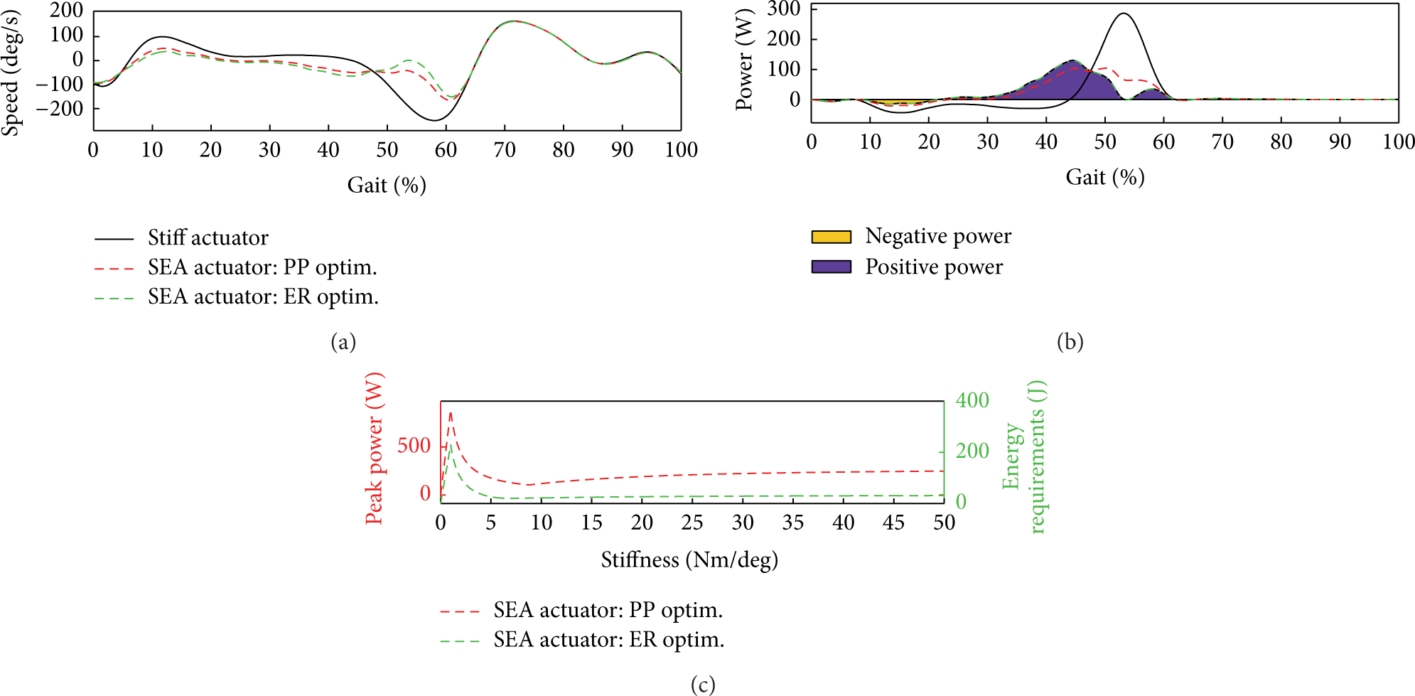
Speed and power versus percentage of gait during human walking and series spring optimization. The lower graph indicates the existence of a minimum for both the energy requirement (ER) and peak power (PP) when varying the series spring stiffness. The stiffness of the series spring for minimized PP is 8.8 Nm/deg and for minimized ER is 6.8 Nm/deg. The corresponding energy requirements are given in Section 4 (see Table 1).
At the Arizona State University (ASU—United States), the SPARKy project (Spring Ankle with Regenerative Kinetics) [55] uses a robotic tendon actuator (including a 150 W Brushed DC motor—Maxon RE40) [56] to provide 100% of the push-off power required for walking while maintaining intact gait kinematics. The first prototype (SPARKy 1 shown in Figure 10(a)) [57] was shown to store and release approximately 16 J of energy per step, while an intact ankle of a 80 kg subject at 0.8 Hz walking rate needs approximately 36 J [58]. A second prototype (SPARKy 2—Figure 10(b)) was built with a lighter and more powerful roller screw transmission and brushless DC motor. Both designs’ working principles rely on a SEA attached between the heel and the leg. This robotic tendon is controlled to provide the ankle torque and power necessary for propulsion during gait. The third prototype (SPARKy 3—Figure 10(c)) [59, 60] was designed to actively control both inversion and eversion as well as plantar flexion and dorsiflexion while providing high power for running and jumping. To the author's knowledge, the SPARKy 3 prototype has not been built. This research finally led to the development of the powered prostheses ODYSSEY (Figure 10(d)) and JackSpring (Figure 10(e)), commercially available through the company SpringActive (http://www.springactive.com/). Yet, no published material is known to the authors concerning those devices.
Ankle-foot prototypes within the SPARKy Project at Arizona State University (USA). (a) SPARKy 1 [55–58]. (b) SPARKy 2. (c) From left to right: SPARKy 1, 2, and 3 [59, 60]. (d) ODYSSEY commercially available through SpringActive. (e) JackSpring commercially available through SpringActive. Figures (d) and (e) adapted from http://www.springactive.com/.

Inspired by the SPARKy project at ASU, researchers of the Universite Catholique de Louvain (UCL—Belgium) have built a 2-degree-of-freedom (DOF) TT prosthesis. The device is actually the missing link between the SPARKy 2 and SPARKy 3 prototypes. It consists of a similar arrangement of springs in the foot in series with a motor assembly and a 2-DOF ankle joint as is found in the SPARKy 3 design. Unlike the latter, the ankle-foot prosthesis has only one actuated DOF, while the inversion and eversion of the foot are passively constraint. After optimization of the mechanical design parameters, the motor was required to provide 60 W (without losses). Therefore a 120 W Maxon EC-powermax 22 with a 4.8: 1 reduction and ball screw assembly was chosen to fulfil the requirements of the ankle-foot prototype. The intent of the authors was to develop a new control strategy based on adaptive oscillators [61, 62].
At Marquette University, Milwaukee (United States), a powered ankle prosthesis, which utilizes a four-bar mechanism in conjunction with a spring and motor was developed. A proof-of-concept prototype, shown in Figure 12(a), was designed by Bergelin et al. [63] optimized, fabricated, and tested with the purpose of demonstrating its ability to match crucial ankle moments during the stance phase of gait. To power the prototype, a Yaskawa SGMAH-02AAN21 200 W motor mated with a right angle gearhead (10: 1 ratio, 95% efficiency) was used. Thanks to the high efficiency of the gearhead, the motor only needs to provide 158 W to achieve the peak power requirement of 150 W at the ankle joint. Precision torque, displacement, and velocity values are measured and controlled by, respectively, an incremental encoder, DACs, and ADCs through the use of a dSPACE DS1104 real-time interface board. Although this prototype was not designed for testing with amputees, results from bench testing were relatively in accordance to expected values. To show the effectiveness of the device with amputees, a second prototype was developed shown in Figure 12(b). The prototype uses a Maxon RE40 DC Brushed motor (48 V-150 W) and custom 50: 1 right-angled gearhead capable of providing the estimated desired torques and velocities during walking [64, 65]. The prototype weighs 2.23 kg (approx. 50% of the previous prototype). During preliminary bench testing, it was shown that the prosthesis was able to recreate 80.1% of the desired reaction forces [66–68].

Zhu et al. [69] at Peking University (China) developed the TT prosthesis PANTOE shown in Figure 13. This prototype uses two SEAs, one for the ankle joint and the other for actuating the toe joint. To provide the torques to the ankle an 83 W brushed DC motor is used, while a 30 W DC brushed motor is taken for the toe joint actuation. When both motors are not functioning, the PANTOE prosthesis can act as a traditional passive prosthesis with spring-like characteristics. The angle range of the ankle joint goes from 20 deg dorsiflexion to 30 deg plantarflexion and the ankle range of the toe joint is from 0 deg to 90 deg dorsiflexion. The PANTOE weighs 1.47 kg (not including the rechargeable battery) which is within the acceptable range for a prosthesis prototype. According to the authors [69], experimental results indicated that the PANTOE prosthesis improved the walking performance of amputee compared with a commercial passive one. Joint angles and vertical ground reaction forces of both prosthetic and sound sides have been shown to be symmetrical.

Ankle prosthesis prototypes developed at Peking University, China [69].
(b) Series Elastic Actuation with Parallel Spring (SEAPS). An actuation scheme with a spring in series and in parallel (SEA + PS) has the potential to lower both the motor torque and speed. Considering the PEA from the previous section, the optimal stiffness for the series spring for minimal PP and ER can be studied. As depicted in Figure 14, the optimization shows that both ER and PP decrease for increasing stiffness of the series spring with its minimum at infinite stiffness. This means that compared to the PEA, the motor requirements remain the same. However, using an SEA presents interesting assets with regard to shock absorption and thus presents a more robust actuator assembly for applications like prosthetics.

Spring stiffness optimization for energy requirement (ER) and peak power (PP) in the case of a series elastic actuator with parallel spring (SEA + PS). It can be seen from the graph that neither of the optimizations show a minimum. As a matter of fact, the stiffer the series spring of the SEA, the better for ER and PP. This means that a regular PEA is actually more energy efficient or requires less peak power. However the series spring of the SEA presents interesting assets with regard to shock absorption and mechanical protection of the electric drive.
At the Massachusetts Institute of Technology—MIT (United States), in the lab of Au et al. [70, 71], a major portion of the research on powered prosthetic feet with electric actuators is conducted as can be seen in Figure 15. The three main prototypes are discussed based on published material. A prototype powered foot prosthesis was built composed of a high-power output DC motor, a transmission, a series spring, a unidirectional parallel spring, and a carbon composite prosthetic foot. The first three components were combined to form a rotary SEA. This actuator was used to modulate the joint stiffness/damping as well as to provide the motive power output for active push-off. This device was intended to focus on control design.

Picture taken from http://biomech.media.mit.edu/. From left to right: 2 ankle-foot prototypes leading to the Herr et al.'s first operating powered foot. 2 prototypes leading to the design of the PowerFoot One. An extra prototype followed by the commercialized ankle prosthesis BiOM.
The powered foot prosthesis [72, 73] has been developed using a combination of a spring and a high-power series elastic actuator. Its working principle consists of loading a spring during the controlled dorsiflexion phase and to activate a torque source (SEA) in parallel when peak power is needed. As a result of this, energy is added to the system to provide push-off. A peak output torque of 140 Nm and power output of 350 W can be applied with a torque bandwidth up to 3.5 Hz. This prosthetic device has shown its effectiveness by improving the metabolic economy of walking individuals with TT amputation, by 7 to 20% on average compared to evaluated conventional prostheses [74, 75].
To the author's knowledge, today, there are only few bionic feet available on the market that provides active push-off properties. iWalk (http://www.biom.com/), a spin-off company from the research at MIT, recently commercialized the “BiOM” prosthesis Figure 15. The BiOM is a bionic lower-leg system designed to replace the lost muscle function of the ankle, Achilles tendon, and calf muscles by propelling the amputee upwards and forwards during walking. It is a completely self-contained device weighting approximately 1.8 kg and having the size of an intact biological ankle-foot complex. The foot includes a passive low profile Flex-Foot minimizing hereby ground contact shock to the wearer. A unidirectional leaf spring acts across the ankle joint when the ankle and the foot are perpendicular to each other. The devices also includes a Powermax EC-30, 200 W, 48 V Maxon motor operated at 24 V, a belt drive transmission with 40/15 reduction ratio, and a 3 mm pitch linear ball screw. The theoretical maximum torque that can be generated by the motor through the drivetrain is about 340 Nm. The series spring consist of a Kevlar-composite leaf spring which is connected to the ball nut with a direction dependent moment arm. Thanks to this, the actuator's stiffness is different for positive and negative torque outputs. All power for the prosthesis is provided by a 0.22 kg lithium polymer battery having a 165 Wh/kg energy density. This battery is able to provide a day's power requirements including 5000 steps of powered walking. The device also includes a neuromuscular control exhibiting an inherent adaptation to ground slopes without explicit sensing of terrain variations. In a preliminary study on two transtibial amputees walking over level terrain at a controlled speed (1.25 m/s), average reductions of 8% in peak impact resultant force, 18% in impact resultant force loading rate, 8% in peak heel-strike foot pressure, and 15% in the first peak knee external adduction moment were observed when the powered ankle-foot prosthesis was compared to the conventional passive prosthesis [76–79].
Following the previous research goals at Vanderbilt University (United States) in pneumatically actuated transfemoral prostheses, Sup et al. designed a self-contained electrically driven device [80] capable of accommodating to slope walking [52]. The device, shown in Figure 16(a), was originally designed for an 85 kg user, walking at a cadence of 80 steps/min and stair climbing. The actuation for the prosthesis is provided by two motor driven ball screw assemblies that drive the knee and ankle joints, respectively, through a crank-slider mechanism. Each actuation unit consists of a Maxon EC30 Powermax brushless motor (200 W). The ankle unit additionally incorporates a steel compression spring with stiffness of approximately 38 N/mm in parallel with the ball screw to supplement power during the ankle push-off. A maximum ankle torque of 130 Nm is provided with a peak power of 250 W, while for the knee the maximum torque and peak power are approximately 75 Nm and 150 W. The ankle and knee range of motion are set from −45 deg to 20 deg, respectively, and 0 deg to 120 deg. The total mass of the device is 4.2 kg, which is within an acceptable range for transfemoral prostheses and comparable to a normal limb segment. Power consumption measurements on level ground indicate that the device consumes on average 66 W at a walking speed of 5.1 km/h for a 75 kg subject, providing hereby more than 4500 strides, or 9 km, of walking between battery charges. Developed by Shultz et al. [51], the Vanderbilt transtibial prosthesis (Figure 16(b)) consists of a Maxon EC30 4-pole brushless motor (200 W), which in conjunction with a 143: 1 transmission ratio can generate a maximum ankle joint torque of approximately 70 Nm. The ankle-foot prosthesis uses a parallel spring which is implemented with an open loop torque compensation algorithm to assist the motor in supplying a restoring torque when the ankle is dorsiflexed. The device has a range of motion of 45 deg of plantar flexion and 25 deg of dorsiflexion. Its mass, including battery and electronics, reaches 2.3 kg. Compared to other existing powered prosthesis, the controller neither depends upon myoelectric control nor utilizes a high gain position control structure, hereby not enforcing a predefined trajectory. The device also does not utilize ground contact sensors. To minimize both the quantity of sensors and build height without loss of functionality, only joint position and velocity, as well as shank acceleration and absolute angular velocity information, are measured. Although less than was estimated for a healthy ankle, preliminary evaluation of the device showed that the powered prosthesis was clearly transferring significant net energy (approx. 8 J/stride) to the user. The ankle-foot device has been integrated in an ankle-knee prosthesis as shown in Figure 16(c). Future work of the authors will consist in further evaluation of the device and extend the controller's capabilities to other forms of gait [81].

(c) Variable Stiffness Actuation (VSA). At the Vrije Universiteit Brussel (Belgium), the CYBERLEGs project consists of a robotic system constituted of an active cognitive artificial leg for the functional replacement of an amputated limb and a wearable active orthosis (developed at SSSA) for assisting the contralateral sound limb. The first prototype CYBERLEGs α-prototype (Figure 17(a)) [82], designed for transfemoral amputees, consists of a variable stiffness MACCEPA-type actuator (200 W Brushless DC motor) [11, 38] that is able to provide 100% of the push-off properties at the ankle combined with a passive knee joint consisting of locking and unlocking mechanisms to fix springs in place to imitate the knee joint torque-angle characteristics. This complex set of locking mechanisms was incorporated to enable energy transfers between the knee and the ankle in the late stance phase of walking. The advantage of using variable stiffness is that the latter can be optimized considering different steplengths, walking speeds, and terrain adaptation. Drawbacks of this type of actuator are the added complexity and weight to the system. In order to reduce as much as possible the extra weight in the CYBERLEGs ankle module, a very small motor was selected with a very high reduction ratio to vary the stiffness of the joint. This way the stiffness of the ankle joint cannot be changed during one stride but during a series of steps providing slow adaptation to different gaits. Currently the device is being evaluated in laboratory environment.

(d) Variable Stiffness Actuation with Parallel Spring (VSAPS). To the author's knowledge, no TT prosthetic device has currently been developed using a variable stiffness actuator augmented with a parallel spring.
(e) Explosive Elastic Actuation (EEA). In general, the explosive elastic actuator (EEA) consists of a spring behind a locking mechanism placed in series with a SEA. This catapult-like mechanism's physics is based on the usage of stored energy to hurl the payload, without the use of an explosive. The EEA therefore has the advantage of harvesting and storing energy to release it when needed, in one shot, hereby creating an energetic explosion. This kind of explosive motions is also required and widely used in, for example, jumping [83], kicking [84], throwing [85], and hammering robots [86]. The torque requirements of the EEA are identical to the SEA. But thanks to the locking mechanism, the motor can work for a longer time period (typically 3 times for a prosthetic ankle) and therefore reducing by the same amount its actuator speed and power.
The Robotics & Multibody Mechanics Research group at the Vrije Universiteit Brussel (Belgium) has also been working on the AMP-Foot prototypes. The AMP-Foot 2 (Figure 17(b)) is an energy efficient powered ankle-foot prosthesis based on a principle of optimal power distribution [87]. This prototype works similarly to devices using a SEA, except for the fact that the actuator works during the complete stance phase. This has the advantage to reduce by approximately 3 times the necessary electrical power rating of the electric drive while still being able to mimic the full mechanical power and torque characteristics of a sound ankle-foot complex. The transtibial prosthesis uses the so-called catapult actuator [12] providing a maximum torque and peak power output of 130 Nm, respectively, 250 to 350 W. The catapult actuator consists of a 60 W brushed DC motor (Maxon RE30) coupled to the ankle joint with a series spring assembly (the push-off springs) and a locking mechanism. The locking of the actuator is ensured by a four-bar linkage mechanism moving in and out of its singular position. Thanks to this, the catapult actuator can be loaded without affecting the kinematics or dynamics of the ankle-foot complex and all the stored energy can be released using very small forces (neglectable compared to the locked ones) when needed for propulsion. In the foot, a second spring (called the plantarflexion spring) is placed making the device behave like a regular ESR foot when the four-bar linkage is closed. A great advantage of this is that in case of a power failure, the wearer is free to remove the motor assembly from the device. Although the device will not provide any push-off properties in such case, the ankle-foot complex still behaves like a very efficient articulated energy-storing-and-returning foot.
As a followup of the AMP-Foot 2, the AMP-Foot 3 is developed at the VUB. This prototype uses an extra locking mechanism in order to mimic the change in rest position of the robotic ankle after foot-flat is achieved. Thanks to this extra locking mechanism more gravitational energy can be stored in the PF spring. As an effect of this the motor actuating the catapult actuator is rated to only 40 W (efficiency included). Therefore, a 50 W maxon brushless motor has been selected. The prototype is currently being tested; research outcomes are expected for June 2014.
4. Comparison Analysis of Propulsive Bionic Feet and Their Preferred Actuator Technology
In Table 1 an overview is given of the electric actuator technology in propulsive prosthetic feet with their main requirements to provide push-off during walking at normal cadence. This actuator comparison considers a 75 kg subject walking at ±1 stride/s and producing about 25.7 J per stride [6]. E
S
represents the gravitational potential energy that can be buffered in elastic potential energy, while E
G
corresponds to the remaining energy to be provided by the actuator during one stride. In the case of a stiff actuator, positive and negative power have to be provided by the actuator (25.7 J + 9.5 J = 35.2 J). TPeak represents the peak torque that has to be generated by the actuator,
To summarize, there is no perfect solution. Every actuator has its own advantages and disadvantages. It should also be noted that variable stiffness actuation present the same characteristics as regular SEA except that they might be adapted for different walking speeds or other possible scenarios.
In Table 2 an overview is given of today's propulsive bionic feet including their main characteristics in which
amp. level is amputation level for which the prosthesis is originally intended;
fig. is figure number of the corresponding picture in the paper;
actuation is type of used actuation based on the proposed categorization: stiff actuation, series elastic actuation (SEA), series elastic actuation with parallel spring (SEAPS), variable stiffness actuation (VSA), and explosive elastic actuation (EEA);
T versus SA is tethered versus stand-alone device;
status is CAD design (CAD), under construction (UC), bench testing (BT), clinical trials (CT), and commercially available (CA);
weight: is the approximate weight of the prosthesis without battery pack;
ankle DOF is the degrees of freedom at the ankle joint;
toe joint is the availability of a toe joint (passive, active, or none);
complexity is the complexity of the prosthesis mechanics from fairly complex (+) to highly complex (+ + +); this classification is subjective and only represents the author's opinion;
adaptability to other gaits is the device able to adapt to different gaits (running, stair ascent and descent, walking on slopes) based on published data;
— is info. unavailable.
As can be seen, only one device proposes the use of a stiff actuator and only a few pneumatic actuations. The overall majority of propulsive bionic feet make use of the series elastic actuator (SEA and SEAPS) [10] while only one prosthesis proposes actuation with a variable stiffness actuator (CYBERLEGs [82]). This tendency is obviously due to the advantage of the SEA to significantly reduce peak power in ankle-foot prostheses. Although the VSA [11] might present interesting assets considering energy efficiency issues for different walking speeds, the research of the team that developed the CYBERLEGs prosthesis [82] is still in its debut phase and has therefore not yet shown its ability to adapt to different gaits. In a near future, one can expect interesting results from this device and an answer to the following question: “Does it pay to use a variable stiffness actuator in a prosthetic foot?” As already mentioned in the previous section, no device has been found using a VSA augmented with a parallel spring. It is clear that if the VSA seems to be beneficial in this type of robotic application, researchers will be experimenting with the VSAPS in a near future.
As a matter of fact most of the research tends to produce stand-alone devices. This is why electric compliant actuation is preferred in new prosthetic designs. Although researchers from the University of Alabama, Vanderbilt University, and the Georgia Institute of Technology have put effort in the development of a stand-alone pneumatic setup [42], their research status in lower-limb prosthetics is unclear to the authors.
It is also noticeable that the weight of the devices tends to reach about 2 to 2.5 kg, except for the transfemoral devices including a knee joint and therefore reaches to about 4 kg. From clinical trials it is known that the lower the weight of a transtibial prosthesis, the more comfort it will provide to its wearer. The best devices in this category are the PowerFoot from MIT [70, 72–75], the BiOM commercialized by iWalk [77–79], and the SPARKy prototypes from the Arizona State University [55, 57, 58]. The ODYSSEY and JackSpring prosthesis, following the SPARKy prototypes commercialized by SpringActive, are expected to give similar results. Yet no published data has been found to confirm the author's thoughts.
When analyzing the actuators characteristics one can see that, as expected, the power rating of motors in a SEA setup vary from 120 to 200 W with exception of the PANTOE of Peking University [69] which utilizes a 83 W motor at the ankle and another 30 W motor to provide compliant actuation at the toe joint. Experimental data shows that ground reaction forces of the sound limb and the amputated limb are of equivalent magnitude. It is also noticeable that the explosive elastic actuation (EEA) principle tends to significantly reduce the power rating of the electric drive with only 60 W for the AMP-Foot 2 [12, 13, 87] and 50 W for the AMP-Foot 3 while still providing a maximum output torque of 130 Nm. Although its added complexity because of the use of mechanical locking systems, the weight of these prostheses remains reasonable (approximately 2.5 kg). Further optimization of the prototypes will have to answer the following question: “Is this added complexity on the actuator level really beneficial to the overall prosthesis behavior?”
Most of the powered ankle foot prostheses have one degree of freedom (DOF), at the ankle, with the exception of the SPARKy 3 from ASU, the missing link between SPARKy 2 and 3 built at the UCL, the PANTOE from Peking University, and the AMP-Foot from the VUB. The SPARKy 3 [59] prototype was presented as a concept prototype providing also active inversion and eversion of the foot. Although the added complexity of the mechanics and control, the concept looked very promising. Therefore, the authors still wonder why this prototype has never been built. The AMP-Foot 2 prototype [12, 13, 87] provides a passive toe joint in addition to its ankle actuation and the PANTOE [69] is the first prosthesis to provide active actuation at the toes which seems to be beneficial to its wearer. Experimental results have shown that the powered toe joint can share the energy cost of the ankle joint hereby providing satisfactory performances in terms of energy efficiency and stability during experiments with amputees.
Furthermore the authors have rated the complexity of the prostheses mechanics. It is important to note that this classification is subjective and only a representation of the author's opinion. Devices which are rated to be the most complex are the pneumatically actuated prosthesis with its rocket-like propellant [42], the SPARKy 3 concept design [59] because of its complex mechanical design and necessary control, the PANTOE [69] with the added complexity of actuated toe joints the AMP-Foot prototypes [12, 13, 87] because of their complex sets of locking mechanisms.
Last but not least, the adaptability of each device (as found in the literature) is represented through 3 different tasks: running, stair ascent and descent, and walking on slopes. The best device in this category is the SPARKy 2 prototype [55, 57, 58] which has shown to support these 3 tasks. Other devices have the potential to be highly adaptable but still need to prove it.
In the table the research status of every device is also given providing an indication of maturity in the technology. As already mentioned previously, only three devices are yet commercially available (CA), that is, the ODYSSEY and JackSpring through SpringActive and the BiOM through iWalk [77–79]. However it is expected that devices that have already undergone clinical trials will slowly evolve to commercial products in the next coming years. The highest potential candidates at first sight seem to be Vanderbilt University's transfemoral prosthesis [51, 53, 81] and the Vrije Universiteit Brussel's AMP-Foot [12, 13, 87] and CYBERLEGs prototype [82].
Most of today's research in (propulsive) bionic feet is focused on the regeneration of torque and power at the ankle joint with very few considerations of the effects of the foot complex. As a result of this, most prosthetic devices use rigid feet with a few exceptions segmenting (passively or actively) the toe joint. It is important to note that the foot also plays a significant role in walking in various aspects such as walking speed, stride length, ankle plantarflexion range, joint angular velocity and energy output, balance, shock absorption, and disturbance rejection, to name a few [88–90]. As a matter of fact, foot features such as its morphology, structure, and the used materials, as well as the actuation and control, have the potential to considerably affect the functionalities of ankle prostheses [91–93]. The authors strongly believe that more attention should be given to the foot complex and that this will probably become the trend for the next generation bionic ankle-foot prostheses.
5. Conclusions
In this paper the authors have presented the current state of the art in propulsive bionic feet. In the introduction section the context of this review paper is outlined followed by a brief description of background information concerning human biomechanics and basic criteria for new prosthetic designs. In Section 3 a new categorization (Figure 3) based on the actuation principle of propulsive ankle-foot prosthesis is proposed with their respective benefits and corresponding bionic feet presented. In Section 4, the authors present a comparison analysis of the previously presented devices and discuss general tendencies and thoughts.
It is strongly believed that powered prosthesis have the potential to improve amputee gait. However most of the research prototypes are not yet ready to cross the gap between use in laboratory environment and use in daily circumstances. As presented in this review study yet two companies have emerged from university research, that is, iWalk and SpringActive and commercialize robotic prostheses. Undoubtedly more designs will be developed and possibly brought to the market in the coming years as assistive robotics are a young and emerging technology offering incredible opportunities for the future.
Conflict of Interests
The authors report no conflict of interests. The authors alone are responsible for the content and writing of the paper.
Footnotes
Acknowledgments
This work has been funded by the European Commission's 7th Framework Program as part of the Project Cyberlegs under Grant no. 287894, the European Commission ERC Starting grant SPEAR under Grant no. 337596 and the Beijing Nova Program under Grant no. Z141101001814001.