
Abstract
Direct numerical simulation method is used to investigate the small scale (d p < η/10) turbulence modulation for a spatially evolving free round jet. Because the turbulence modulation phenomena can not be accurately measured by experimental method, the turbulence modulations are poorly understood. The particle diameter in our simulation is smaller than the Kolmogorov length scale η (d p < η/10), and the point force method can be accurately used for the research of small scale turbulence modulation based strictly on the theory of point force method. The simulation uses an explicit coupling scheme between particles and the fluid, which considers two-way coupling between the particle and the fluid. The DNS results are compared with experimental data with equal Reynolds number (Re = 1700). The particles modulation on the fluid turbulence properties and coherent vortex structures are quantitatively given in our paper, and some new findings on the particles modulation are explicitly explained in this paper, which will further refine our understanding of intricate mechanism of small scale (d p < η/10) turbulence modulation for a spatially evolving free round jet.
1. Introduction
Numerical simulation method is becoming a valuable tool in the research of particle-laden flows. As far as we know, there are two methods named Eulerian-Eulerian or Eulerian-Lagrangian approach for the numerical simulation of particle-laden flow. Mashayek and Pandya [1], Loth [2], and Yin et al. [3] used the Eulerian-Eulerian method in the particle-laden flow research, in which the particles are treated as a continuum phase. Mashayek and Pandya [1], Loth [2], and Minier and Peirano [4] gave very good reviews of the two methods on the particle-laden flow. Balachandar and Eaton [5] carefully reviewed the current experimental and computational techniques for turbulent dispersed multiphase flows, including the strengths and limitations.
Zhang and Reese [6] conducted a gas turbulence modulation research in a two-fluid model for gas-solid flows. Their main contributions of this work were that the interparticle length scale, which is usually ignored, was incorporated into a new model for determining the turbulent length scale. Simulation results for fully developed steady flows in vertical pipes were compared with experiment data. Crowe [7] developed a model for the investigation of turbulence modulation in particle-laden flows. The model was based on volume averaged equations for the kinetic energy of the carrier phase. Yarin and Hetsroni [8] studied the particle-turbulence interaction. They showed that finer particles damped the turbulence, and coarser particles enhanced it. They also found that the level of turbulence modulation was affected by four parameters: the particle mass loading ratio, the particle-fluid density ratio, the particle Reynolds number Re p , and the ratio of the particle diameter to the characteristic eddy diameter.
Boivin et al. [9] used the direct numerical simulation method to investigate the turbulence modulation by particles in isotropic turbulence. They found that particles increasingly dissipated fluid turbulent kinetic energy with increasing particle loading, with the reduction in kinetic energy being relatively independent of the particle relaxation time. Hwang and Eaton [10] used the experimental method on the investigation of turbulence modulation in a homogeneous and isotropic turbulence with small heavy particles (S t = 50). From their experimental research, the particles attenuated the fluid turbulence kinetic energy and viscous dissipation rate with increasing mass loadings. The attenuation levels reached 35–40% for the kinetic energy and 40–50% for the dissipation rate at the highest mass loadings. Tanaka and Eaton [11] used a high resolution particle image velocimetry (PIV) system to experimentally investigate the small-scale turbulence structures that affected the overall turbulence modulation. Three-sized particles were used in their research, 500 μm glass, 250 μm glass, or 250 μm polystyrene particles at mass loading ratio up to 0.45. The turbulent kinetic energy was attenuated by up to 25% in the presence of particles, but the changes of dissipation rate are smaller than changes of turbulent kinetic energy. But as far as we know, there are scare researches on the turbulence modulation for the spatial evolving free round jets.
For the point-force method used in DNS on the investigating of small scale turbulence modulation, the particles have to be significantly smaller than the grid size, which is still a large burden on numerical simulation of particle-laden flows by DNS method. On one hand, the DNS is computationally expensive for tracking large numbers of particles using E-E or E-L method. On the other hand, the DNS simulation must obey the rules of d p ≤ η (where d p is the diameter of nozzle, and η is the Kolmogorov scale), which significantly restricts the diameters of particles used for DNS simulation. Recently, Balachandar [12] gave a very good review of the point-particle approaches to turbulent multiphase flows. By the comparative analysis of the different computational approaches for turbulent multiphase flows, Balachandar [12] proposed that point-particle approach is uniquely suited to turbulent multiphase flow where the Stokes number is greater than 1. The stokes number is defined as the ratio of particle time scale to Kolmogorov time scale τ p /τ k . Balachandar [12] also did some Stokes number estimates in order to find which range is ideally suited for the point-particle approach and found that the point-particle approach may be more effective for very heavy particles for the DNS of turbulent multiphase flow. In our paper, the particle density is larger than that of the carrier fluid (ρ p ρ f = 2500), and the particle diameter for the largest sized particles (d p = 60 μm) in our simulation is much smaller than the smallest turbulence scale named Kolmogorov length scale η (d p < η/10), which will be explicitly explained in the following part on the computational process. Then our DNS on the research of particles modulation effect is on a sound theoretical footing based on the viewpoint of Balachandar [12]. In addition, the particle modulation effect based on the DNS results for the low Reynolds number free round jets can provide a supplemental method, which is not easy by the experimental method considering the difficulty of experimental measurement and the accuracy in the experimental research. Recently, Tanaka and Eaton [11] conducted an experimental research on the particle modulation of small scale turbulence by the highly resolved particle image velocimetry measurements. Because the experimental method can not accurately capture the small scale turbulence on the order of the particle diameter or the Kolmogorov scale η, the small-scale effects remain poorly understood. The experimental research of Tanaka and Eaton [11] gave us valuable information on the small scale turbulence modulation on the order of particle diameter or the Kolmogorov scale. When the particle diameter is smaller than the Kolmogorov scale η (d p < η/10), the experimental method is even more difficult to measure the small scale turbulence modulation by the particles, and there are no experimental data found in the literature nowadays. But for the DNS point force method, the small scale turbulence modulation can be accurately captured when the particle diameter is larger small than the Kolmogorov scale η (d p < η/10) based on the analysis of Balachandar and Eaton [5, 12].
In our research, the main objective is to use the DNS method on the investigation of different sized particles (d p = 10 μm, d p = 30 μm, and d p = 60 μm) on the modulations of the turbulence properties and coherent vortex structures. The particle diameter is smaller than the Kolmogorov scale η (d p < η/10) and DNS results of the small scale turbulence (d p < η/10) modulation are quite valuable for the further understanding of intricate mechanism of particle modulation, which is still a large burden for experimental measurements. There are scare researches on the modulation of vortex structures for a spatially evolving of round jet [13]. Our research will give other researchers a clear understanding of different sized particles on the modulation of coherent vortex structures and the turbulence properties in the fully developed region, which is quite different from that found in the wall-bounded flows, such as pipe flow [14, 15], channel flow [16–23], and Duct flow [24].
2. Numerical Method
2.1. Governing Equations for Fluid
The dynamics of compressible viscous flow is described by the Navier-Stokes equations, which impose the conservation of mass, momentum, and energy. We used the Cartesian coordinates of equations as follows:

where ρ is the fluid mass density, P is the thermodynamic pressure, u i is the velocity along the direction x i , ρe t is the total energy (kinetic + thermal), and Fp → f is the feedback force to the fluid by the particles in each computational cell.
We assume the fluid is Newtonian and can be described by the ideal-gas law, thus the above system is able to be closed by the following relations:

where T is the absolute temperature and R is the gas constant R c /W (R c = 8.314 J/(mol K) and W is the gas molar weight).
The dynamic viscosity of the fluid μ is expressed by the Sutherland's law:

where T0 = 293.15 K, μ0 = 1.69 × 10⁻⁵ kg/(m·s), and S = 120.0 K.
The heat flux along x i , namely, q i , is described by the Fourier law:
2.2. Governing Equations for Particles
For the simulation of particles, several assumptions about the behavior of particles are made. (i) All particles are rigid spheres with identical diameter d p and ρ p . (ii) The ratio of the material density of particle to fluid approximates to 2500. (iii) The fluid is considered as dilute two-phase flow. Thus the interaction between particles is neglected. (iv) The particles are injected into the flow-field with uniform distribution at the nozzle and their velocity is equal to the local gas-phase velocity.
In the present work, the standard Stokes drag, the Slip-shear lift force, the Slip-Rotation lift force, and the gravity force are considered as the main forces acting on a sphere. Since the density ratio of gas to solid being considered is of the order 10−3, the Basset force due to unsteady history effect and the virtual mass force due to acceleration of fluid surrounding the solid particle is small compared to the drag the lifts. Thus, they are neglected. Finally, the equation to govern the particle motion is expressed as follows:

where
3. Numerical Schemes
The above governing equations are discretized on a three-dimensional regular rectangular Cartesian grid using eight-order, explicit finite-difference derivatives for advective and diffusive terms. Boundary closures to the derivative operators are 3,3,4,6-8-6,4,3,3 [26]. When the resolution is high enough, no spatial filtering is necessary due to numerical stability of the arrangement. The classical fourth-order six-stage low-storage Runge-Kutta method is used for time integration. As for the round jet, the use of a Cartesian grid avoids the numerical difficulties inherent to cylindrical coordinates near the origin axis.
4. Computational Domain and Flow Parameters
The computational properties used in our DNS are similar to that of Yuu et al. [27]. In our DNS simulation, the streamwise length is about L x = 20D, where D is the circular diameters, and the transverse and the spanwise are the same; that is, L y = L z = 10D, which is similar to that in Li et al. [25]. The transverse and the spanwise length is larger than that of Yuu et al. [27], which is found to be small for the simulation of a spatially evolving round jet. The inlet centerline streamwise velocity is U1 = 3.19 m/s, and the circular diameter is D = 8 mm, corresponding to a bulk Reynolds number Re b = U1 × D/ν = 1700. There is not a coflow velocity in our DNS simulation so that the coflow velocity is set to U2 = 0.0. The detailed computational parameters can be found in the work of Li et al. [25]. The time-step is made dimensionless using the inlet circular diameter D as a reference length-scale and the bulk velocity U1 as a reference velocity. The following is the time scale used in our DNS simulation:

In our DNS simulation, a starting location of each particle at the nozzle outlet is set by using uniformly random number. The number of particles injected at the nozzle outlet is determined by both the mass loading ratio and the diameter of particles. The mass loading ratio is defined as Z m = M d /M c , where M d is the mass of the dispersed phase and M c is the mass of continuous phase.
The computational particles are not used in our simulation, because the number of particles used in particle simulation is directly associated with the accuracy of turbulent properties, such as mean particle velocity and particle Reynolds stress. The minimum number of particles used in our simulation is about 200,000, which is also dependent on the particle diameters and mass loading ratio. In our DNS simulation, we consider the two-way coupling between fluid and particles, and the interparticle collision is omitted because our particle-laden flow belongs to the dilute two-phase flow, considering the results of Laín and García [28] that interparticle collision is effective when the mass-loading ration is larger.
We simulated particles with density ratio of ρ p /ρ f = 2500, ρ f = 1.12 kg/m3. From the research of Sbrizzai et al. [29], we know that particles with different diameter will interact selectively with the coherent structures, depending on their Stokes number [30]. For this reason three diameters of particles (d p = 10 μm, d p = 30 μm, and d p = 60 μm; S t = 0.3, S t = 2.7, and S t = 10.9, resp.) are used in our simulation. The S t number is defined as S t = τ p /τ f = (ρ p d p 2/18·μg)/(D/U1). The mass loading ratio chosen in our work is Z m = 0.6. Simulations are run until the particle's Eulerian velocity statistics become stationary in time. The total time of computation is about 260τ, where τ is defined in (6).
5. Validation of Point Force Method for DNS Particle-Laden Flow
In order to validate our DNS grid resolution on the Kolmogorov scale for the point force method in the DNS of particle-laden round jets, we have carefully done a grid resolution test before conducting this project. The ratio between the largest length scale, L, and the Kolmogorov scale, η, is L/η = Re m 3/4, where Re m is the Reynolds number based on the largest length scale and the turbulence intensity. The largest length scale, L, is estimated in our research to be L = 10D, and the turbulence intensity is 4.5%, which is an approximate value from engineering research. Then the Re m is determined as Re m = Lu′/υ = 238. When the Re m number is determined, the Kolmogorov scale, η, is computed as η = L/Re m 3/4 = 0.1625D. In our research, the nondimensional grid spacings in three directions are ΔX/D = 0.125, ΔY/D = 0.0625, and ΔZ/D = 0.0625, respectively. Then the Kolmogorov scale is nearly equal to the computational grid spacing, and the Kolmogorov scale is relatively larger than the grid spacing used in our research. For the largest diameter particles used in our DNS is d p = 60 μm = 7.5 × 10⁻³D = 0.05η < η/10. So the point force method is strictly satisfied in our DNS for the particle-laden round jet [5, 12]. The investigations on the small scale turbulence modulation (d p < η/10) are based on a sound theory footing, and the results from our DNS are quite valuable for the further understanding of small scale turbulence modulation, which can not be accurately measured by experiment methods [5, 12].
6. Boundary Conditions
At the jet inlet, the inflow longitudinal velocity is the same as for instability studies carried out by Silva and Metais [31]:

where U1 is the jet centerline velocity, U2 is a small coflow velocity, R0 is the radius of the nozzle, and θ is the momentum thickness of the upstream shear layer. In our DNS research a value of θ/R0 = 0.01 is used, which is similar to that used in Li et al. [25].
7. Results and Discussions
7.1. Code Validation
We conduct a two-phase round jet simulation. We compare our DNS results with experiment data of Yuu et al. [27]. In all the plots, the simulation results and experimental data are both chosen at x = 16d. The complete validations for the turbulent properties between DNS and experimental data of Yuu et al. [27] are given in Li et al. [25]. For the detailed information on the validation process and analysis of the DNS results, see the literature Li et al. [25].
7.2. Coherent Vortex Structures and Particles Dispersion
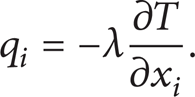
For the spatial evolving of particle-laden round jets, the addition of different sized particles in the particle-laden jet will modulate the three-dimensional coherent vortex structures. In order to give a clear understanding of the particles modulation on the coherent vortex structures, considering the two-way coupling between the particles and carrier fluid, Figures 1(a)–1(g) present the Q vortex and particle dispersion in the particle-laden jets with different sized particles. The jet Q vortex structures are identified using the Q-criterion isosurface technique which is based on the second invariant of the velocity-gradient tensor, Q = 1/2(Ω ij Ω ij − S ij S ij ), Ω ij , and S ij , respectively, being the antisymmetric and symmetrical parts of this tensor. Figures 1(d)–1(g) show the three-dimensional evolution of Q vortex colored by the vorticity magnitude in the particle-laden jet and free air jet, respectively. In the near-field region contours of vorticity field can clearly reflect the triggering off the K-H instabilities. The shedding of axisymmetric vortex rings is observed clearly after the core region, which is the characteristic of saturation of the Kelin-Helmholtz instabilities. The large scale hairpin vortex structure becomes more rapidly in the downstream. These hairpin vortices have been observed experimentally at moderate Reynolds numbers by Lasheras and Meibuerg [32] in the free air jet. Comparing the Q vortex in the particle-laden jet and free air jet, we find an interesting phenomenon that the Q vortex structures in the particle-laden jet develop more upstream than that in the free air jet, considering the length of the evolution of axisymmetric vortex rings. The possible reason can be resulting from the disturbances by the addition of particles. The physical size of large scale hairpin vortex structures in the particle-laden jet in the downstream direction is larger than that in the free air jet, in which the physical size of hairpin vortex structures is relatively small. The large-scale hairpin vortex structures become more obvious during the jet development in the downstream direction in the particle-laden jet than that in the free air jet. The changes of the hairpin vortex structures in the particle-laden jet may come from the modulation by the addition of particles. Our DNS simulation captures the particle dispersion phenomenon with different sized particles well. For the small sized particles shown in Figure 1(a), the particles are just like fluid traces and the particle dispersion well represent the carrier fluid coherent vortex structures. For these small sized particles, inertia mechanism is the main reason for their dispersion. In our simulations all individual real particles are tracked, not a number of representative particles. The total number of particles in Figure 1(a) is the order of 20 million. For the intermediate sized particles shown in Figure 1(b), the particles dispersion exhibits an interesting phenomenon. For these sized particles, inertia is still the main drive for the particles disperse more than the fluid. Except for the inertial mechanism explained above, we also found some particles collect preferentially in certain regions. Comparing the vortex magnitude and particle dispersion shown in Figures 1(b) and 1(e), we can clearly see that some particles disperse more than the carrier fluid. The possible reason can be explained as the centrifugal mechanism. So the particle dispersion for the intermediate sized particles is controlled by both the inertia and the centrifugal mechanism. Inspecting the three-dimensional particle dispersion for the small and intermediate sized particles shown in Figures 1(a) and 1(b), we also find some particles exhibiting small-scale clustering about a few diameters away from the jet nozzle, especially for the intermediate sized particles, in which this small-scale clustering is more obvious comparing with the small sized particles. We propose that this small-scale clustering is the symbol for the particle preferential concentration. For the large sized particles in Figure 1(c), the particles dispersion in the transverse direction is significantly prohibited because of the inertia mechanism. Some particles far from the nozzle also exhibit small-scale clustering, which is similar to that found in Figures 1(a) and 1(b). Although the inertia mechanism is strong enough for these sized particle dispersions in lateral direction, we can also find some particles surrounding the near-axis region, forming elongated, quasistreamwise clusters called rib clusters. Longmire and Eaton [33] also found the formation rib clusters. This rib clusters is mainly caused by centrifugal mechanism explained explicitly in the preceding section, although the centrifugal mechanism is not strong enough for these particles to disperse more than the carrier fluid, which is significantly restricted by the particles inertia mechanism. From the above analysis, the inertia mechanism is the main drive for the particles dispersion regardless of the size of particles. But for the intermediate sized particles, the combined effects of inertia mechanism and centrifugal mechanism cause the particles to disperse more than other sized particles. The centrifugal mechanism is dependent on both the particles diameters and the surrounding vortex structures, such as the rapid appearance and disappearance of rids, which is found by other researchers before for the single phase round jets flow [34, 35].
Qvortex and particle dispersion in a three-dimensional spatial evolving particle-laden round jet. (a), (d): S t = 0.3, d p = 10 μm. (b), (e): S t = 2.7, d p = 30 μm. (c), (f): S t = 10.9, d p = 60 μm. (g): free air jet.
7.3. Modulation on the Turbulence Properties
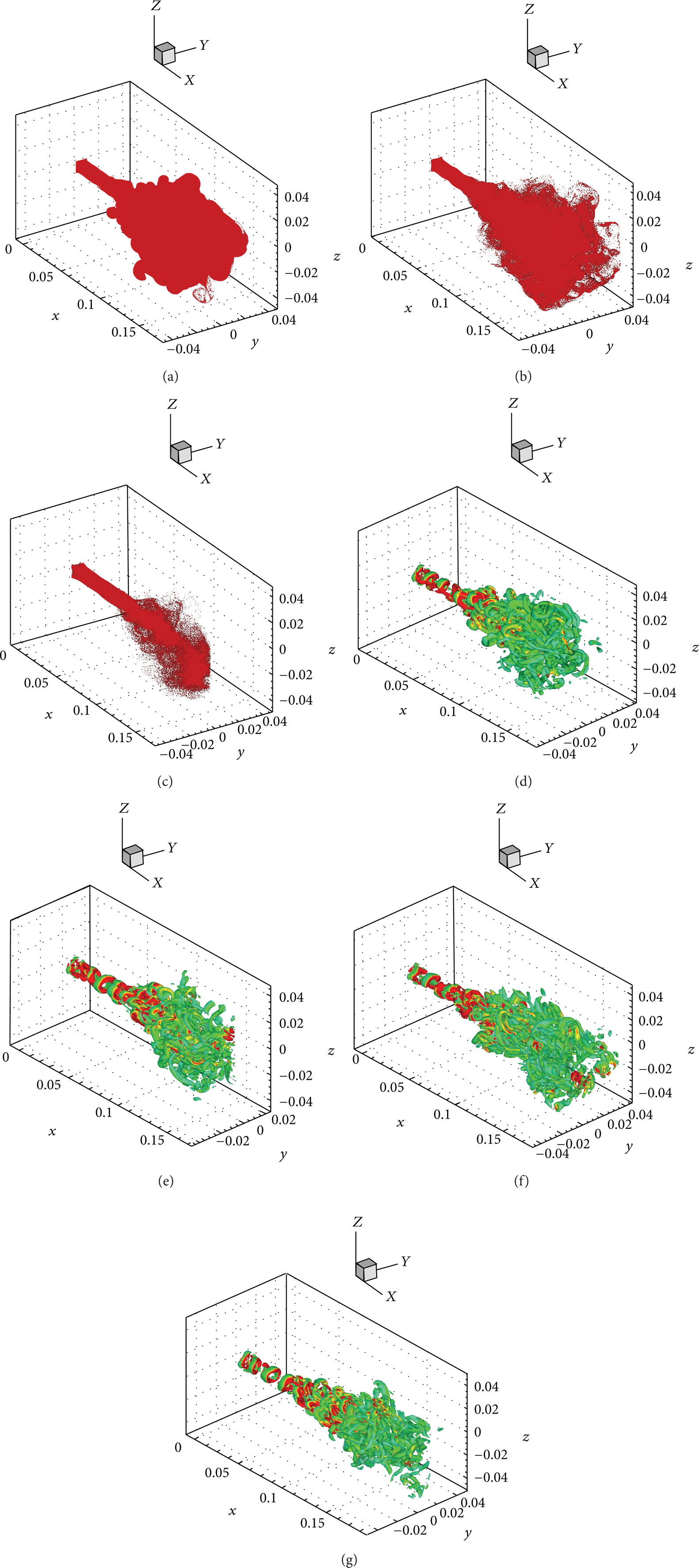
In order to give a quantitative measure of particle modulation on the carrier fluid, the fluid turbulence properties in the particle-laden jet are presented in this section. Figure 2(a) shows the half-width of the fluid along axial direction with different Stokes number or different diameter particles. From the comparison between the half-width in the particle-laden jet and free air jet, we can see that the particle diameter takes an important part in the modulation of half-width. In the core region ranging from X/D = 0 to X/D = 6, the half-width is a constant value about 0.5, regardless of the particles diameter. After the streamwise position at X/D = 6, the half-width for d p = 10 μm particle is relatively larger than that in the free air jet, and the half-width for the d p = 30 μm or d p = 60 μm particle is smaller than that in the free air jet. It means that the addition of particles delays the fluid mean streamwise velocity decay for the larger diameter particles (d p = 30 μm, d p = 60 μm) but speeds up the mean fluid streamwise velocity decay for the small diameter particles (d p = 10 μm). The mean fluid streamwise velocity decay along the streamwise direction shown in Figure 2(b) gives us the same idea of particle modulation on the mean streamwise velocity. For the intermediate and larger sized particles, the particles effectively drag the carrier fluid. Then the mean fluid streamwise velocity decays less than that in the free air jet for these sized particles. But, for the small sized particles, the particles can easily follow the carrier fluid. Then the mean fluid streamwise velocity decays nearly equal to that in the free air jet.
(a) Half-width along axial direction with different Stokes number particles. (b) Streamwise mean air velocity decay along axial direction with different Stokes number particles.
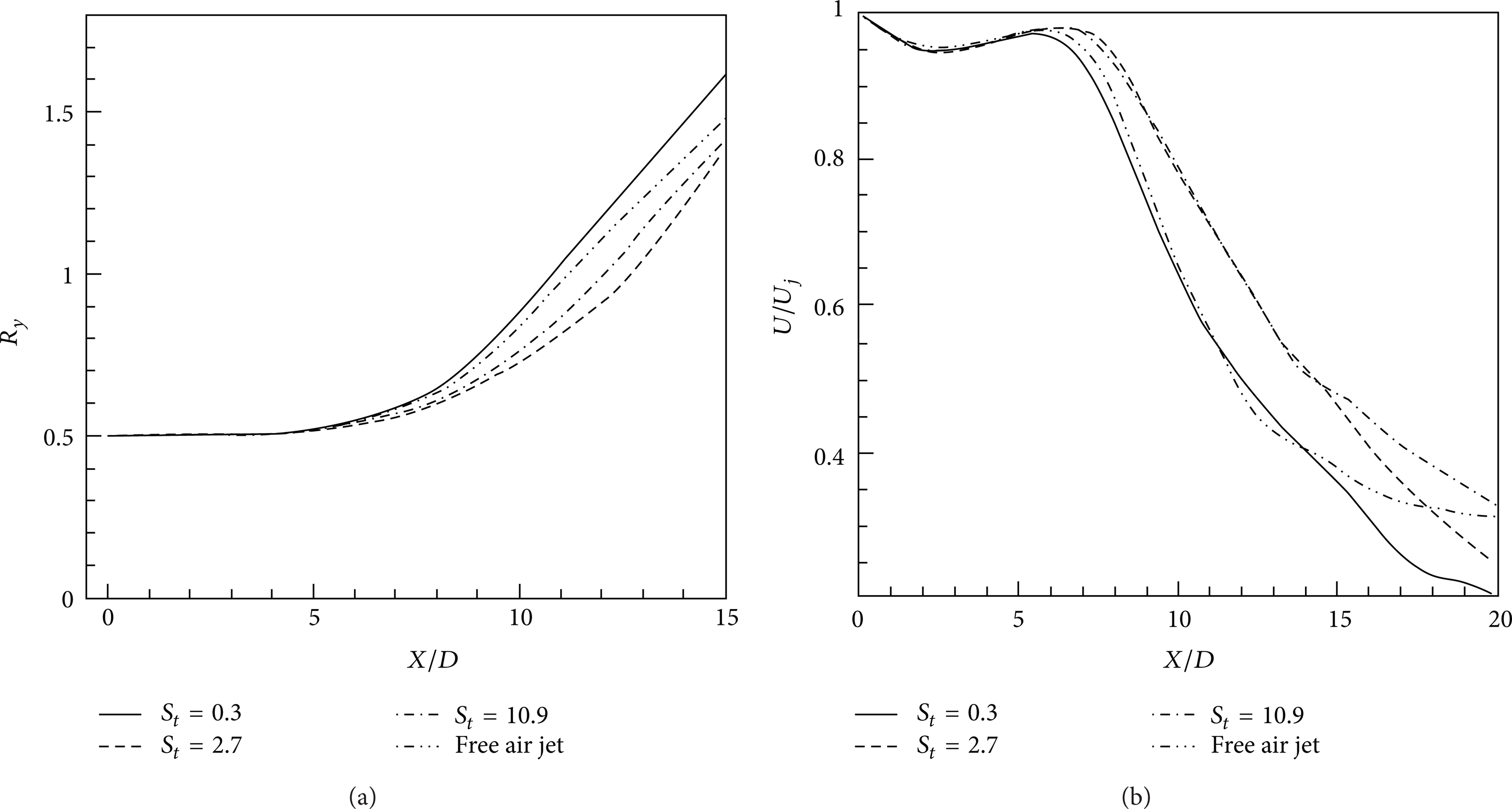
The mean fluid streamwise velocity in the radial direction is shown in Figure 3(a) in the flow developed region at X/D = 18. The data presented in Figure 3(a) are chosen at the streamwise position X/D = 18 in the fluid developed region. It seems that the particle diameter takes a negligible effect on the modulation of mean fluid streamwise velocity in the region r/r y < 2, but after that region there are some differences. For the intermediate and larger sized particles (d p = 30 μm, d p = 60 μm), the mean fluid streamwise velocity decays slower than that in the free air jet in the region r/r y > 2. The possible reason may be that in this region r/r y > 2, the particles drag the carrier fluid. Figure 3(b) shows the mean particle velocity in the radial direction. The data are also chosen at X/D = 18. From the Figure 3(b), for the larger diameter particles (d p = 60 μm), the interactions between the fluid and particles are small; the particle velocity decay is less influenced by the carrier fluid. Then the particles decay quickly than that of the small diameter particles. For the small sized particles (d p = 10 μm), the particles are just like fluid tracers. Then the interactions between surrounding fluid and particles become more rapidly during the jet development. The small sized particles receive momentum flux from the surrounding fluid, so the velocity decay along the streamwise direction is delayed comparing with large sized particles. When the particle diameters have large difference, the decay effect is more notable.
(a) Streamwise air velocity decay along radial direction with different Stokes number particles. (b) Streamwise particle velocity decay along radial direction with different Stokes number particles (x = 16d).
Figures 4(a)–4(d) show the fluid Reynolds stresses (〈uu〉, 〈vv〉, 〈ww〉, 〈uv〈) in the radial direction with different diameter particles in the flow developed region at X/D = 18. The fluid normal Reynolds stresses in this paper are defined as the root mean square of the turbulence fluctuations. It should be noted that the Reynolds stresses (〈uu〉, 〈vv〉, 〈ww〉, 〈uv〉) are obtained by grid transformation from the Cartesian grid to the Cylindrical grid. Then the Reynolds stresses 〈uu〉, 〈vv〉, and 〈ww〉 are the streamwise Reynolds stress, radial Reynolds stress, and azimuth Reynolds stress, respectively. From the comparison for the normal stress 〈uu〉 shown in Figure 4(a) with different diameter particles in the particle-laden jet, it is seen that the normal stress 〈uu〉 is significantly attenuated by the intermediate and larger diameter particle (d p = 30 μm, d p = 60 μm). The decreasing rate for the maximum Reynolds stress 〈uu〉 is about 50% for the large sized particles. The normal stress 〈uu〉 for the small diameter particles (d p = 10 μm) in the particle-laden jet is relatively larger than that in the free air jet, which means that the addition of particles slightly increases the fluid turbulence fluctuations for these sized particles. Figure 4(b) shows the Reynolds normal stress 〈vv〉 with different diameter particles. It is seen that the smaller particles (d p = 10 μm) enhance the turbulence fluctuations. The increasing rate of the maximum Reynolds normal stress 〈vv〉 for the small sized particle is about 14.8%. The larger particles suppress the turbulence fluctuations. The decreasing rate of the maximum Reynolds stress 〈vv〉 for the larger sized particles is about 26%. For the intermediate sized particles (d p = 30 μm), the normal stress 〈vv〉 in the particle-laden jet is nearly equal to that in the free air jet in the region of r/r y > 0.1, but, in the near axial region r/r y < 0.1, the normal stress 〈vv〉 in the particle-laden jet is slightly modulated by the addition of particles. Figure 4(c) shows the normal stress 〈ww〉 with different diameter particles. The modulation effect for the three diameter particles is similar to that shown in Figure 4(b). The particles slightly increase the Reynolds stress 〈ww〉 for the small sized particle (d p = 10 μm), and the increasing rate is about 13.4%. For the intermediate and larger sized particles (d p = 30 μm, d p = 60 μm), the Reynolds stress 〈ww〉 is attenuated, especially for the larger sized particles, and the decreasing rate is about 23%. Figure 4(d) shows the shear stress 〈uv〉 with different diameter particles in the developed region. By the inspection of the maximum shear stress, it is seen that the maximum shear stress in the particle-laden jet moves towards larger r/r y value, especially for the small sized particles. The smaller diameter particles significantly increase the turbulence fluctuations. The increasing rate of maximum Reynolds shear stress 〈uv〉 for the small sized particles is about 31.2%. The maximum value for the intermediate and larger diameter particles is positioned towards a large r/r y value comparing with that in the air jet, and the particles decrease the turbulence fluctuations for these sized particles in the region with maximum shear stress. The decreasing rate of the maximum Reynolds stress 〈uv〉 for the larger sized particles is about 25%. From the above analysis, the addition of particles significantly attenuates the Reynolds stress 〈uv〉 for the intermediate and larger sized particles but significantly increase the Reynolds stress 〈uv〉 for the small sized particles. From the above analysis we can clearly see that the turbulence normal Reynolds stress is more strongly attenuated in the streamwise direction than in the transverse direction for the intermediate and large sized particles, especially for the large sized particles.

(a) Radial profiles of the u-root mean square for the air with different Stokes number particles. (b) Radial profiles of the v-root mean square for the air with different Stokes number particles. (c) Radial profiles of the w-root mean square for the air with different Stokes number particles. (d) Radial profiles of Reynolds shear-stress for the air with different Stokes number particles.
Figure 5 shows the kinetic energy in the radial direction in the flow developed region at X/D = 18. It is seen that the intermediate and larger sized particles significantly decrease the kinetic energy, and the kinetic energy for the smaller sized particle is nearly equal to that in the free air jet. The decreasing rate of the maximum kinetic energy for the larger sized particles is about 42%, and for the intermediate sized particles this rate is about 32%. So the addition of particles significantly reduces the kinetic energy for the intermediate and larger sized particles (d p = 30 μm, d p = 60 μm). Because the normal stresses (〈uu〉, 〈vv〉, 〈ww〉) for the smaller sized particles are slightly modulated by the particles, the profile of kinetic energy for the smaller sized particles changes little in the particle-laden jet.
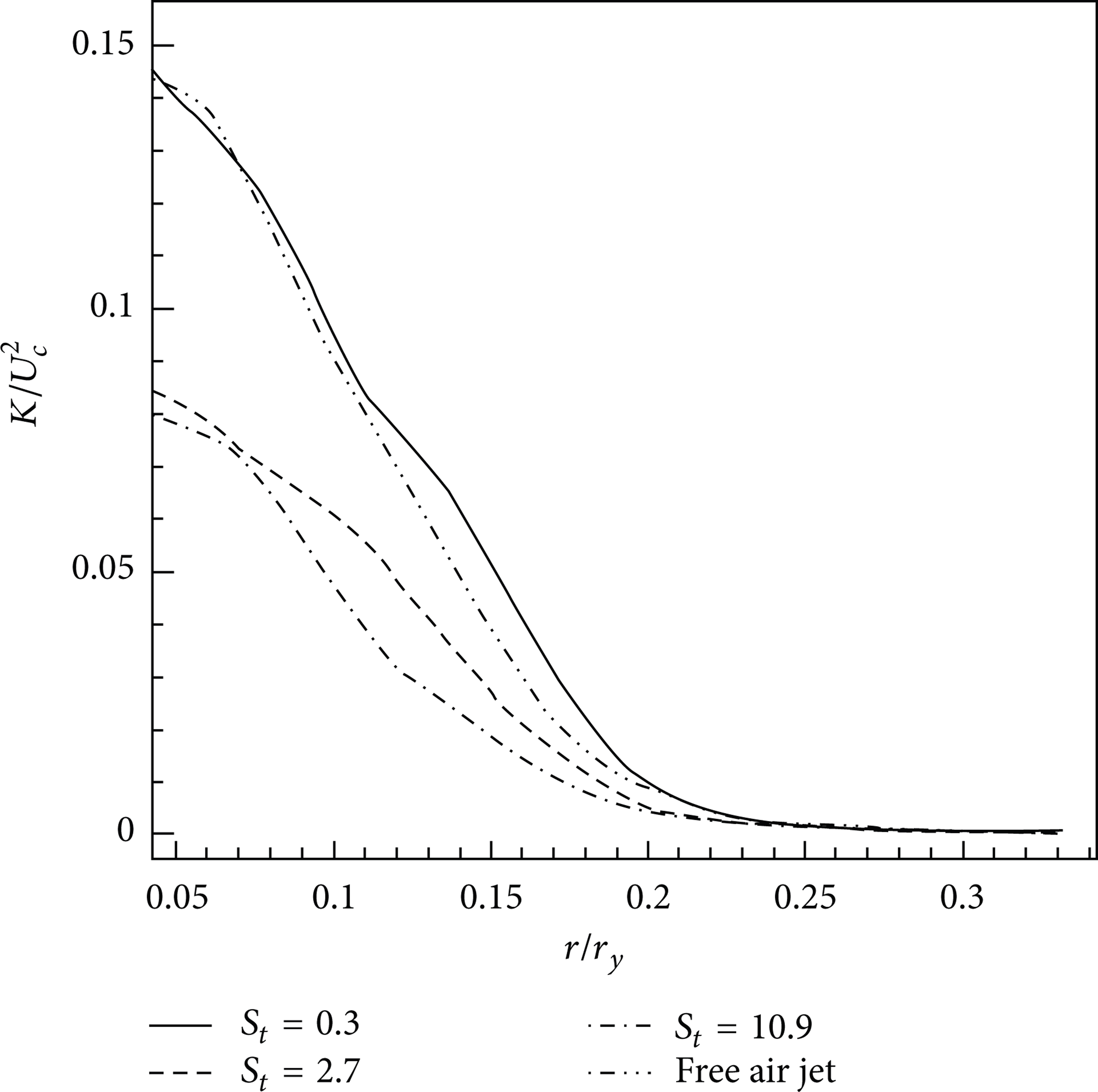
Kinetic energy decay along radial direction with different Stokes number particles.
Few researches have done on the numerical simulation of spatially evolving free particle-laden round jets. The particles modulations on the fluid turbulence properties with different sized particles in the developed region have not well known considering the complex effect of particles modulation. These results on the modulation of turbulence properties in the fully developed region above will further enhance our understanding of the modulation effect on fluid turbulence for a particle-laden free round jet.
8. Conclusions
We conduct a direct numerical simulation research for the particle-laden turbulent flows in a spatially evolving low Reynolds number axisymmetric jet, using the Eulerian-Lagrangian point-particle approach. The investigations of small scale turbulence modulation are strictly based on the theory of point force method (d p < 10η) and small scale turbulence modulation results from our DNS can give valuable information on the intricate mechanism of turbulence modulation, which is scarce in the literatures for the free round jet. From our numerical simulation results, we find the following results.
The three-dimensional Q vortex structures develop more upstream in the particle-laden jet than in the free air jet, considering the length of the evolution of axisymmetric vortex rings. The physical size of the hairpin vortex structures in the downstream direction is larger than that in the free air jet, and the hairpin vortex in the particle-laden jet becomes more obvious in the downstream during the jet development than that in the free air jet.
The three-dimensional particle dispersion processes are well captured by our DNS simulation with a high spatial and time resolution. Some particles exhibit small-scale clustering about a few diameters from the jet nozzle, especially for the intermediate sized particles. For the larger sized particles, this small-scale clustering becomes more downstream. We propose that the small-scale clustering is the symbol of particle preferential concentration.
The addition of particles delays the fluid mean fluid streamwise velocity decay for the intermediate and large sized particles but speeds up the mean fluid streamwise velocity decay for the small diameter particles. The particles take a negligible effect on the modulation of mean fluid streamwise velocity in radial direction in the region of r/r y < 2, but after that region there are still some differences.
The particles on the modulation of Reynolds stresses take a very complex effect in the fully flow developed region. The turbulence normal Reynolds stress is more strongly attenuated in the streamwise direction than in the transverse direction for the intermediate and large sized particles, especially for the large sized particles. The kinetic energy in the particle-laden jet is significantly decreased for the intermediate and larger sized particles, and the decreasing rate of the maximum value for the turbulence kinetic energy reaches to about 42%, but, for the small sized particles, the particles modulation on the kinetic energy is not so apparent.
It seems that the small scale turbulence modulation (d p < η/10) on turbulence properties (velocity, half-width, and Reynolds stress) are directly associated with the modulation of vortex structures. They both control the turbulence modulation for the particle laden round jet. The detailed analysis of the small scale turbulence modulation (d p < η/10) on the turbulence properties and vortex structures in this research will further refine our understanding of particle modulation effect, which is still a large burden for the fully resolving of this unanswered problem.
Footnotes
Notation
Conflict of Interests
The authors declare that there is no conflict of interests regarding the publication of this paper.
Acknowledgment
This work was supported by the National Natural Science Foundation (Grant nos. 50736006 and 50976098) of China.