
Abstract
A high precision slit in ultra-high vacuum is designed to develop a good performance soft X-ray interference lithography (XIL) beamline at Shanghai Synchrotron Radiation Facility (SSRF). In order to define the secondary source and enhance the performance of the beamline, many technical difficulties need resolving to design the precision slit. Therefore, to obtain reasonable design scheme, it is necessary to analyze the structural characteristics, the movement situation, the force state, the thermal load state, and the cooling state of the precision slit deeply by numerical simulation. The simulation results and the testing results demonstrate that the mechanical precision of the slit is at a high level and satisfies the requirements of the beamline.
1. Introduction
The soft X-ray interference lithography (XIL) beamline is a branch of the soft X-ray microscopy beamline at Shanghai Synchrotron Radiation Facility (SSRF). Both beamlines share the high brightness X-ray from the same elliptically polarized undulator (EPU). The function of the beamline is to fabricate the nanostructures, and it can be applied in different fields, such as the advanced devices with nanostructure, the cell surface interactions and tissue engineering, and the next generation lithography technology [1–3]. Design goals of the XIL beamline are to scan the photon energy from 85 eV to 150 eV, to get the light spot size of 4 × 4 mm, to obtain the photon flux of 1 × 10¹⁵ ph·s−1cm−2/2.4% BW/0.3 A, and to gain the interference fringe cycle of 50 nm. The performance index of the beamline is on the same level as the XIL beamline of Swiss Light Source (SLS) and the EUV-IL beamline of Synchrotron Radiation Center (SRC) at Wisconsin university.
To establish the high performance beamline, in addition to making full use of the EPU source, it is necessary to shape and process the beam to obtain high quality light spot through a series of optics and precision mechanical devices [4–6]. The beam emitted from the EPU source is reflected by a deflecting mirror and focuses on a precision slit by a focusing mirror and finally shoots the mask through an aperture slot. The precision slit, located at 26 m from the source, is employed to define a secondary source for the beamline, so as to improve the spatial coherence and the quality of the beamline. The precision slit strongly affects the imaging effect and the light spot quality of the beamline, so it is necessary to carefully design the structure of the slit and obtain sufficient mechanical precision to enhance the performance of the beamline. Schematic diagram of the XIL beamline is shown in Figure 1.
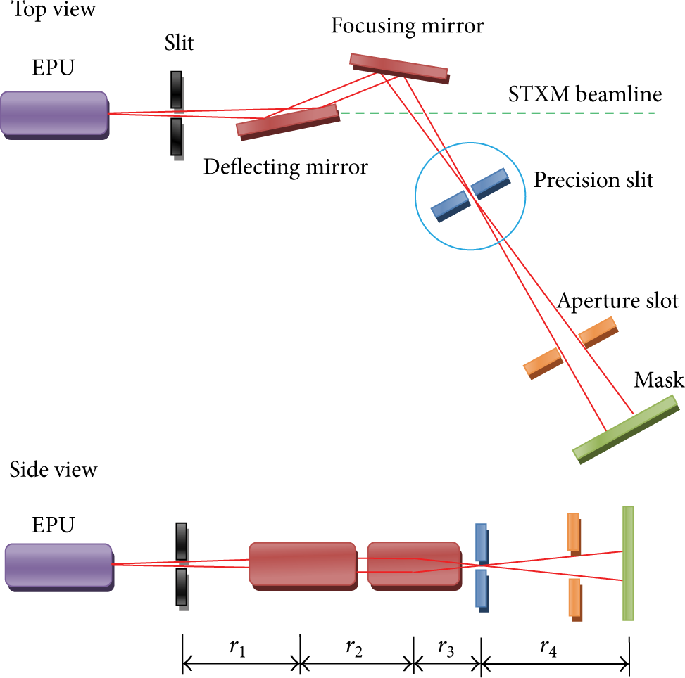
Schematic diagram of XIL beamline.
In order to accomplish the goals of the beamline, by theoretical calculating, it is found that the blades of the precision slit should open from 5 μm to 250 μm, the linear resolution and the repeatability of the blade should be better than 0.25 μm and 2 μm, respectively, the parallelism of the blade edges should be better than 2.5 mrad, and the linearity of blade edge should be better than 2.5 μm. There are many different types of precision slit frequently used in the field of synchrotron radiation, such as screw driving type, lever driving type, wedgy box driving type, inclined block guide type, and flexible hinge type [7–11]. In the presented paper, a precision four-blade slit of screw driving type is designed by making the four blades move independently. Besides the technical demands of the blade of precision slit, the displacement resolving power of the precision slit along the direction of beamline should be better than 5 μm so as to position the precision slit accurately.
For the precision slit, the motion accuracy of the blade is limited by the resolution of the linear actuator, the accuracy of the linear guide, and the deformability of the elastic damping structure; the shape accuracy of the blade is affected by the hot deformation of the blade induced by the synchrotron radiation besides the manufacture accuracy. To improve the motion accuracy and shape accuracy of the blade, numerical simulations including motion analysis and thermal analysis are carried out to make the design of the precision slit more reasonable.
2. Structure Design
The precision slit contains two orthogonal blade motion components; each of them includes two blades which can define the secondary source for the beamline. The structure of the precision slit is shown in Figure 2, including four linear actuators, four linear feed mechanisms, two blade motion components, four linear actuator supports, a vacuum chamber, and a sliding table. The two blades of the same blade motion component move independently along two linear guides. To obtain high resolution and repeatability, the linear actuator of M-235.2 DG model from PI Company is adopted. Its travel distance, resolution, repeatability, and axial bearing capacity are 20 mm, 0.1 μm, 1 μm, and 120 N, respectively. In order to position the precision slit accurately in the beamline, a sliding table with high resolving power is adopted.
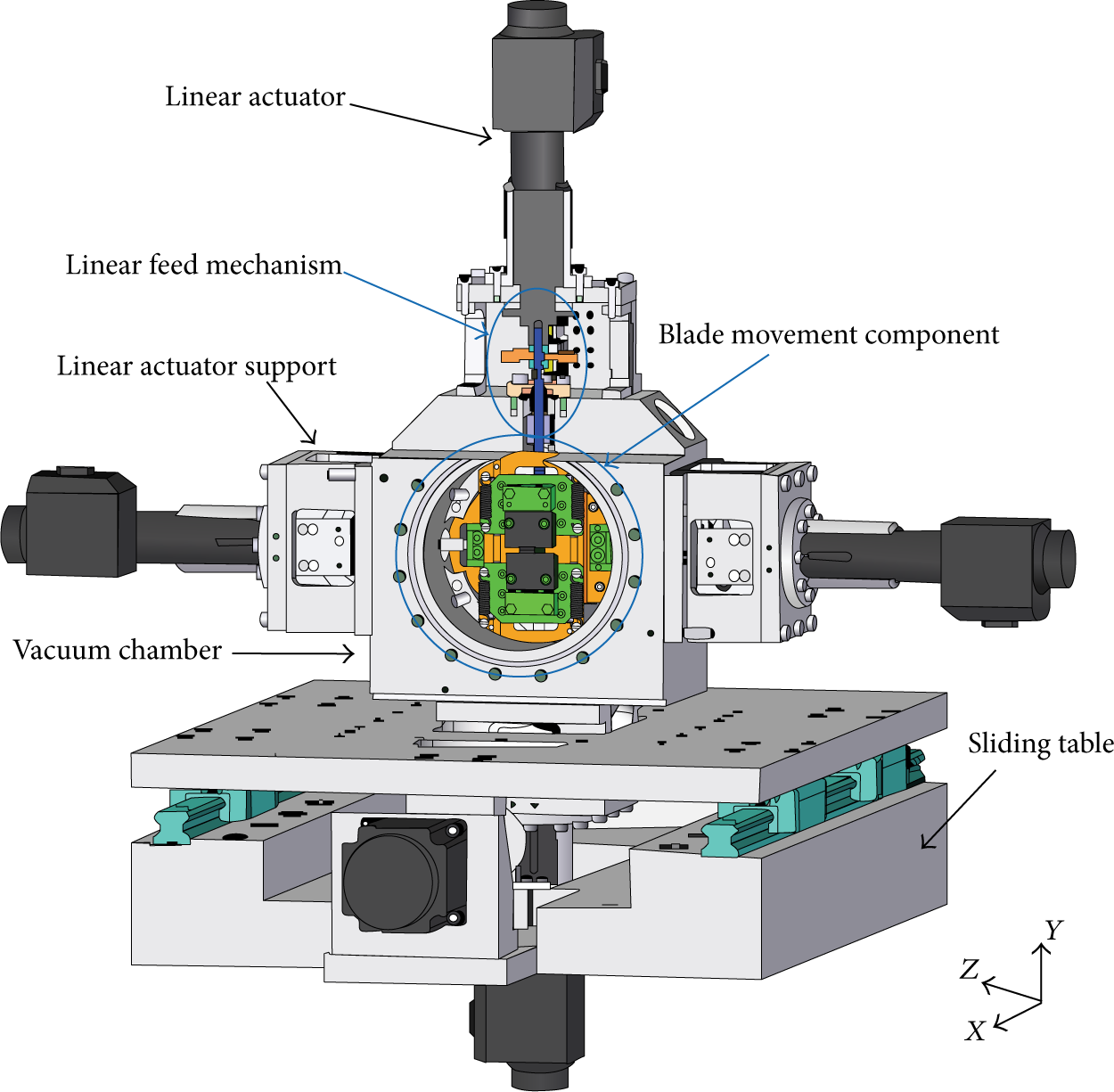
Structure of the four-blade precision slit.
The blade motion component is the key component for the precision slit, and its structure is shown in Figure 3. It consists of the bracket, the connection board, the linear guide, the pushing board, the elastic damping structure (spring, spring connecting rod, etc.) and the blades, and so forth. The linear actuator applies a force on the pushing board and then makes the blade move along the linear guides. But the blade cannot be positioned accurately under the effects of its own gravity and gravities of the pushing board and the connection board. In order to position the blade accurately, the combination of the linear actuator and the elastic damping structure is adopted to make the blade move in a quasistatic state. When the blades move relative to one another, the spring is elongated and generates a counterforce to the action force of the linear actuator. The blade moves very slowly, so the blade is always in a force balance in any positions during its motion process. The force state of the blade is shown in Figure 4.

Structure of the blade motion component.

Force state of blade.
Shape accuracy of the blade edge determines the quality of secondary source directly. The quality of the blade edge is not only related to the machining accuracy, but also related to its hot deformation. Although the precision slit is located at the downstream position, the blade also absorbs considerable heat from the synchrotron radiation. To reduce the hot deformation of the blade edge, the blade is manufactured by a material with high thermal conductivity and low thermal expansion coefficient. By comparing, it is found that tungsten is the most suitable material. Its density, thermal expansion coefficient, elasticity modulus, Poisson's ratio, and heat conduction coefficient are 19273 Kg/m3, 4.6 × 10⁻⁶, 4.0679 × 10¹¹ Pa, 0.28, and 167 W/m°C, respectively.
3. Numerical Simulation
The blade motion component is very important for the precision slit, so ANSYS software is adopted to simulate its motion and hot deformation states to optimize the structure of the precision slit. To make the simulation results more realistic, the finite element model is not simplified as far as possible. Figure 5 shows the FEA model of the blade motion component, almost all the parts are kept in the FEA model except several screws. For the FEA model, it is necessary to find a suitable way to define the linear guide and the elastic damping structure. Actually, the blade slides along two cross roller guides, and rolling friction is produced between the cross roller guides, so the friction force is very small and can be neglected. Therefore, the frictionless mode is adopted to define the contact state between the cross roller guides whose motion state is replaced by a sliding pair. Stainless steel spring is a key part for the elastic damping structure; its shear modulus and middle diameter are G = 8 × 10⁴ MPa and D2 = 5.2 mm, respectively. The diameter of spring wire is d = 0.8 mm, the effective number of turns is n = 18, and the convolute ratio is C = D2/d = 6.5. Therefore, the stiffness coefficient of the spring is calculated as

It is an important parameter to define the spring in the simulation environment.

Finite element model of the blade motion component.
3.1. Motion Simulation
To obtain reasonable size of the secondary source, it is necessary to position the blades accurately. The motion state and position accuracy are affected by the force state of the blade motion component, so it should be studied deeply in the motion process. Figure 6 shows the simulation results. In fact, the blade moves very slowly, and then the inertia caused by its mass can be ignored, so the motion of the blade is simulated by a quasistatic procedure. The linear actuator exerts forces of 5 N, 10 N, 15 N, and 20 N on the pushing board along vertical direction, respectively. When the blades move, the spring is elongated gradually and accumulates certain elastic potential energy to make the blades always in a force equilibrium state. When the elastic force equals the force from the linear actuator, the blade stops and is located in a definite position. The bracket is fixed; the upper blade and the lower blade move relative to one another. The blades close gradually when the spring is elongated with the increase of the force from the liner actuator. The maximal displacements of the blade reach 1.56 mm, 3.13 mm, 4.69 mm, and 6.26 mm, respectively, corresponding to the forces of 5 N, 10 N, 15 N, and 20 N. To position the blade, it should bear a definite force which balances with the elastic force from the spring. Actually, the linear actuator makes the blade move by converting rotary motion into linear motion. When the linear actuator turns an angle, the blade moves a corresponding displacement. In the situation, the linear actuator will bear a counterforce from the spring. To make the blade motion component have a stable performance, the linear actuator should have a loading capacity to prevent being damaged. In Figure 6, when the force of 20 N is exerted on the blades, they close completely, so the maximal force on the linear actuator is about 20 N. The linear actuator with M-235.2-DG model from PI Company is chosen; it can bear the biggest axial force of 120 N, so the design is reasonable.

Displacement of the blade under different forces.
When the blades move, other parts of the blade motion component are also in a stress state which may affect the motion accuracy of the blade and then affect the quality of the beamline. The other parts are made of austenitic stainless steel 1Cr18Ni9Ti, whose yield strength is 200 MPa, and tensile strength is 550 MPa. Figure 7 shows the equivalent stress states of the blade motion component under different forces. The equivalent stress of the blade motion component increases gradually with the increase of the force, and the biggest equivalent stress appears in the elastic damping structure. When the two blades move relative to one another, the spring is elongated gradually, and then the force acting on the two rods increases continuously. The two rods connect to the bracket and the connection board, respectively. They are in a cantilever state, and their roots bear the biggest bending moment. The maximum equivalent stresses reach 7.2 MPa, 14.5 MPa, 21.8 Mpa, and 29.2 MPa, respectively, with corresponding forces of 5 N, 10 N, 15 N, and 20 N. These values are less than the yield strength of 1Cr18Ni9Ti and suggest that the two rods only generate small recoverable elastic deformation. The equivalent stresses in the other parts are near zero, demonstrating that the other parts do not generate deformation nearly. Therefore, it is clear that the motion accuracy of the blades can be guaranteed.

Equivalent stress distribution of the blade motion component under different loads.
The forces from the linear actuator and the elastic damping structure make the blade in a balance state and then position it accurately. The spring stiffness coefficient affects the position accuracy significantly. If its value is too big, it is difficult to make the spring deform, and the linear actuator may bear a larger counterforce from the spring, so it may be damaged easily and results in the invalidation of the secondary source. If its value is too small, the spring is soft and may generate permanent deformation by the force from the actuator. After many experiments, we choose an extension spring with the stiffness coefficient of 1.6 N/mm2. Figure 8 shows the simulation results of the spring deformation depending on the forces of the spring. The deformations of the spring reach 1.5605 mm, 3.1211 mm, 4.6816 mm, and 6.2421 mm, and the forces of the spring reach 2.4969 N, 4.9937 N, 7.4906 N, and 9.9874 N, respectively, with corresponding forces of 5 N, 10 N, 15 N, and 20 N from the linear actuator. The elongations of the spring are linearly related to the force on the spring. The slope of the curve in Figure 8 indicates the spring stiffness coefficient. The forces of the spring are half of the forces from the linear actuator, because two springs are adopted to balance with the forces from the linear actuator. Actually, the displacement of the blade is the same as the elongation of the spring. As long as the step length of the linear actuator is reduced, the displacement resolution of the blade is improved, and the position accuracy of the blade is enhanced.
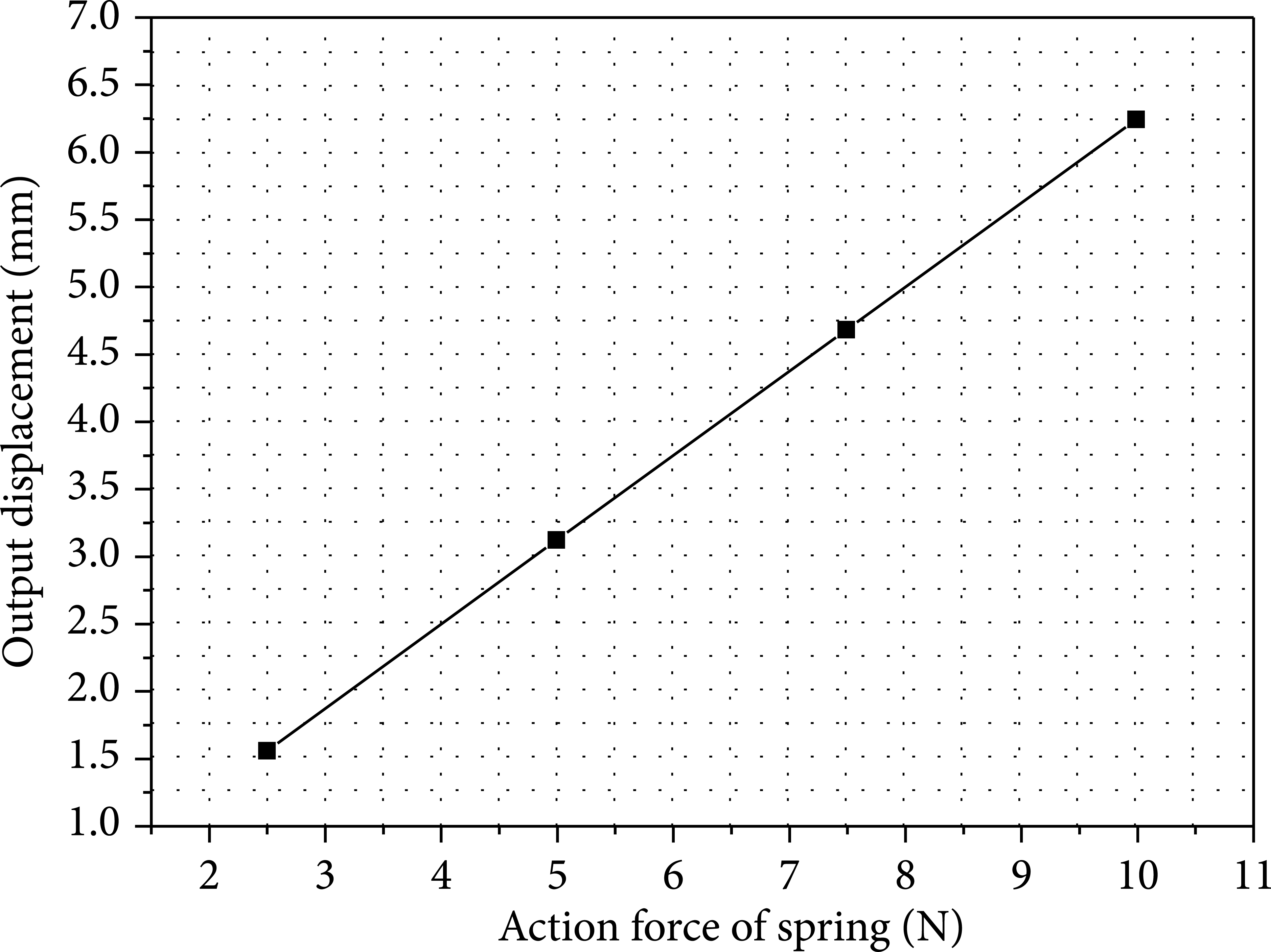
Simulation results of spring deformation depending on the forces from the spring.
3.2. Thermal-Structure Coupling Simulation
The blades in the precision slit are irradiated by the synchrotron radiation when the beamline works. The hot deformation of the blade induced by the heat from the synchrotron radiation degrades the shape accuracy of the blade and then degrades the quality of the beamline. A cooling method with several copper braids is adopted to reduce the hot deformation. Figure 9 shows the photo of the blade motion component; there are four copper braids connecting the blades and the vacuum chamber.

Copper braid cooling method.
The blade motion component works in the high vacuum, so the heat exchange includes heat conduction, heat convection, and heat radiation. The three heat exchange ways are involved in the thermal-structure coupling simulation so as to make the simulation close to the reality.
The thermal load acting on the blade is about 1 W and focuses on the blade edge, and its irradiation area of 66.7 μm × 9.18 μm is shown in Figure 10. The calculation result is obtained by the Shadow VUI according to the reality. The thermal contact resistance between copper and tungsten is 1 × 10⁻⁴m2K/W; the convective heat transfer coefficient is 1 × 10⁻² W/mm2K. Figure 11 shows the temperature fields of the blade motion component in uncooled state and cooling state. In the uncooled state, the temperature between 271.56°C and 273.27°C is observed, and the maximum temperature appears in the blade edge. There are only two ways to transmit the heat from the blade to the outside. One way is to transmit the heat by a few screws connected to the vacuum chamber, and the other way is to radiate the heat to the vacuum. The two ways are not effective in transmitting the heat to the outside, so they can be neglected. In this condition, the temperature rises rapidly and brings bad effects to the blades, the linear guides, and the other parts and finally degrades the quality of the beamline. After cooling, the temperature decreases to 23.94°C by transmitting the heat to the outside through four copper braids and is in an acceptable range. Therefore, the blade motion component avoids the high-temperature effect, and the motion accuracy and the shape accuracy of the blade can be guaranteed. The simulation results show that it is necessary to cool the blade motion component; otherwise, the performance of the precision slit will degrade significantly.

Irradiation area on blades.

Temperature field of blade movement component.
Figure 12 shows the equivalent deformation of the blade motion component in uncooled state and cooling state. The blade edge deforms badly in the uncooled state and still more severely than the other parts in the cooling state. The heat from synchrotron radiation is absorbed directly by the blade edge and then transmits to other parts, so the temperature of the blade edge varies sharply, and the temperature of other parts varies gently. In addition to the temperature variation, the hot deformation of the blade motion component is relative to its structure and the thermal expansion coefficient of the parts. For the parts not restrained, their thermal stresses are relatively small; but for the parts restrained strictly, their thermal stresses are relatively large. When the thermal expansion coefficients of the adjacent parts are similar, their deformations are relatively homogeneous; otherwise, their deformations are relatively inhomogeneous. In the uncooled state, the hot deformation of the blade edge reaches about 0.19 mm and damages the linearity of the blade edge; the hot deformation of the linear guide reaches about 0.08 mm and degrades the accuracy of the linear guide badly. After cooling, the blade motion component deforms slightly, the hot deformations of the blade edge and the linear guide reduce to about 0.2 μm and 0.1 μm, respectively. In this case, the motion accuracy and shape accuracy of the blade can be guaranteed, and it is found that a nice cooling effect is obtained by the copper braids.

Equivalent deformation of the blade motion component.
The hot deformation of the blade edge in the vertical direction (Y direction) affects the quality of the beamline directly, so it is necessary to study it deeply. In Figure 13, the blade edge deforms in a convex shape from 0.0805 mm to 0.0808 mm in the uncooled state and seriously in the two endpoints. After cooling, the convex deformation also exists but reduces to the range from 0.095 μm to 0.1 μm. The middle of the blade edge absorbs the majority of heat, so the area deforms more seriously than both ends, but due to the stress concentration in the uncooled state, the two endpoints also deform badly. Through the simulation, it is found that the blade edge deforms from 0.0808 mm in the uncooled state to 0.1 μm in the cooling state, so the cooling method is very effective in keeping the performance of the precision slit at a high level.

Deformation of the blade edge.
Figure 14 shows the deformations of the blade motion component along Z direction shown in Figure 4 in the cooling state when it is under the forces of 0 N and 5 N from the linear actuator. In both cases, the biggest deformations both reach 0.14 μm and appear in the elastic damping structure; the deformations of the linear guides are 0.015 μm. The phenomenon demonstrates that the linear guides deform slightly in the cooling state when the blade moves, and the motion accuracy is not affected in the motion process of the blade. Through above analysis, it is easy to find that the blade motion component has a high stability during its adjusting process.

Deformations of the blade motion component in the cooling state.
4. Performance Evaluation
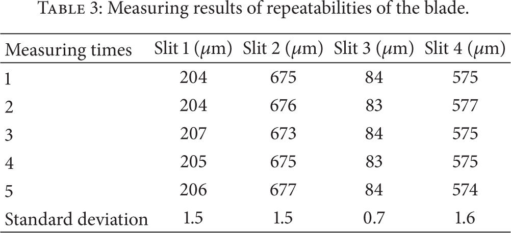
The linearity of the blade edge, the parallelism between two blade edges, and the motion repeatability of the blade determine the quality of the beamline directly and are measured by a three-dimensional measuring instrument with the aid of the image method and the probe contact method. Figure 15 shows the photos of the precision slit and the measuring methods. In Table 1, the linearities of four blade edges are measured, and the measuring results are 1.25 μm, 1.25 μm, 2.5 μm, and 2 μm, respectively. In Table 2, the parallelism of 1.25 μm (0.16 mrad expressed by angle) is obtained. In Table 3, the repeatabilities of the four blades are 1.5 μm, 1.5 μm, 0.7 μm, and 1.6 μm, respectively. All the measuring results meet the requirements of the precision slit.
Measuring results of linearities of the blade edge.

Measuring results of parallelism of the blade edge.

Measuring results of repeatabilities of the blade.

Photos of precision slit and measuring methods.
In order to position the precision slit along the direction of beamline accurately, the sliding table should have higher displacement resolving power. It adopts an Oriental Motor and two THK linear guides. The resolving power of the sliding table is measured by a laser interferometer. Figure 16 shows the displacements of the sliding table at the positions of 0 mm, 5 mm, 10 mm, 15 mm, 35 mm, 40 mm, 45 mm, and 50 mm. There is a near linear relationship between the displacements and the motor steps with the increase of the motor step, demonstrating that a slight difference exists between any two positions. To obtain the resolving power of the sliding table, the differences of the displacements in each step are calculated and shown in Figure 17. At the positions of 0 mm, 5 mm, 10 mm, 15 mm, 35 mm, 40 mm, 45 mm, and 50 mm, the biggest values reach about 0.193 μm, 0.206 μm, 0.209 μm, 0.193 μm, 0.256 μm, 0.198 μm, and 0.220 μm, respectively. Therefore, the value 0.256 μm is chosen as the resolving power of the sliding table and meets the requirement.

Measuring results of displacements of the sliding table per a motor step in different positions.
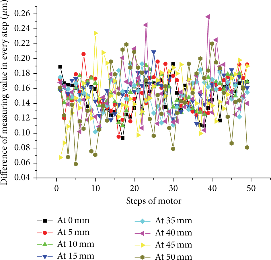
Difference of displacements in each motor step under different positions.
Until now, the precision slit has been installed in the XIL beamline and in a good operation condition. The etching line structure of 100 nm cycles has been manufactured through the XIL beamline. Figure 18 shows the far-field coherent diffraction pattern of 92.5 eV.

Far-field coherent diffraction pattern of 92.5 eV photon.
5. Conclusions
To define the secondary light source of the XIL beamline, a high precision slit in ultrahigh vacuum is designed through a screw transmission scheme. Its structure is described, and its FEA model is established. The motion simulation and the thermal-structure coupling simulation of the precision slit are finished. In the motion process, the biggest equivalent stress of 29.2 MPa appears in the elastic damping structure, but the equivalent stresses of other parts are near zero, demonstrating that the elastic damping structure generates very small recoverable elastic deformation, and other components do not generate deformation nearly. In the uncooled state, the temperature between 271.56°C and 273.27°C is observed, and the shape accuracy of the blade is damaged. After cooling, the temperature reduces to 23.94°C, and the shape accuracy recovers because the high-temperature effect on the critical components is reduced effectively. The performance of the precision slit is evaluated. The linearity, the parallelism, and the repeatability of the blade edge reach 2.5 μm, 0.2 mrad, and 1.6 μm, respectively, and the resolving power of the sliding table reaches 0.256 μm. The performance test results demonstrate that the precision slit is very effective, and it has been working at SSRF in a good operation condition. The continuously adjustable opening is the advantage of the slit, and it can make the best use of the coherent photons. In the future, the XIL beamline will take the soft X-ray interference lithography as the main mean and at the same time be equipped with the electronic etching and reactive ion etching means to provide customers with periodic structure substrate with high density; the period can be small to 50 nm.
Conflict of Interests
The authors declare that there is no conflict of interests regarding the publication of this paper.
Footnotes
Acknowledgment
This work was funded by the National Major Scientific Project of China (Grant no. SS-06, 07093XQ070).