
Abstract
Hybrid electric vehicles have excellent energy efficiency and emission performance. Power split device (PSD) is a key component that directly affects the control strategy of power systems, the economic consumption of fuel, and the dynamic performance of vehicles. A differential-based PSD was proposed in this paper. A traditional differential was taken as the prototype and a new design method is proposed to retrofit the differential into a PSD. First, a comprehensive approach that includes theoretical analysis and software simulation was used to analyze the possibility as well as the necessity of retrofitting the differential into PSD. Then the differential was retrofitted. Finally, finite element analysis and bench test were conducted. Results showed that applying the retrofitted differential as PSD is practicable.
1. Introduction
During the past decade, the decrease in fossil energy and the gradual deterioration of the environment have resulted in increasing attention toward energy-saving, environment-friendly, and high-efficiency hybrid electric vehicles (HEV) in the automotive industry [1–4]. HEVs can generally be divided into three categories: series hybrid electric vehicle (SHEV), parallel hybrid electric vehicle (PHEV), and series/parallel hybrid electric vehicle (SPHEV). The first two categories have several problems; for PHEV, the engine speed is difficult to decouple while, for SHEV, the system efficiency is low because of the secondary conversion of energy. SPHEV overcomes these problems by taking advantage of the engine and motor to improve the whole efficiency of the system. SPHEV is the HEV configuration with the most potential for energy saving.
Power split device (PSD) is the core component of SPHEV. Current research on PSD can be divided into two main aspects: one is that tycoons in global automobile manufacturing, such as Toyota and General Motors (GM), put forward different PSDs successively. In 1999, Toyota proposed the Toyota hybrid system (THS) [5], which was equipped on the Prius. Based on THS, Toyota later developed a new single-row planetary gear configuration [6]. In 2001, Toyota put forward a new configuration that combined THS with continuously variable transmission (CVT) and it was used in the Estima and the Alphard. Then, a special double-row planetary gear configuration was applied in the Lexus GS450h, which was released in 2007. GM also proposed a series of configurations, including double- [7–10] and three- [11–14] row planetary gear configurations. The other research aspect is that numerous studies on the motion characteristics, modeling, and control strategy of PSDs have been conducted. Sasaki [15] studied the configuration characteristics, motion relationship, and control strategy of THS; Miller [16] presented a summary of various PSD architectures; Liu and Peng [17, 18] established the dynamic model of Prius and carried out research on minimum equivalent fuel consumption control strategy and dynamic programming control strategy; Bertoluzzo et al. [19] studied the configuration characteristics of SHEV and PHEV as well as conducting a concrete study on the configuration characteristics and working mode of SPHEV; Syed et al. [20] built a HEV model with Lavina-type PSD and studied its configuration characteristics and function realization; Li and Kar [21] optimized the PSD ratio based on dynamic programming; Gupta and Ramanarayanan [22] discussed the cycle power problem in the planetary gear of HEV; Pennestri et al. [23] proposed a system method to study the efficiency of PSD; Kim and Rousseau [24] compared the control effect of logic threshold control strategy and instantaneous optimization strategy on a HEV using single-mode PSD; Mashadi and Emadi [25] proposed a new PSD with two lockable clutches and studied the configuration characteristics and control strategy of the new PSD; and He et al. [26] presented the use of predictive traffic information to formulate an energy allocation strategy.
Considerable studies have been devoted to the configuration characteristics and control strategy of different PSDs. These research efforts have laid a solid foundation for and contributed significantly to the development of PSD. A review of existing research has convinced the authors of the current study that research on the design of PSD is indispensable. Therefore, the primary focus of this paper is the design of a new, simple, and practical PSD. A new retrofit design method is proposed to design a PSD based on the traditional differential. The similar kinematics characteristics of traditional differential and THS are analyzed, and then traditional differential is considered as a prototype and its retrofit is used as a differential-based PSD (DPSD). Finally, finite element analysis and bench test were conducted to verify the rationality of the DPSD.
The paper is structured as follows. Section 2 proposes the retrofit design method for the DPSD. Section 3 discusses the theoretical analysis and software simulation to analyze the possibility and necessity of retrofit and then presents the retrofitting of the traditional differential. Section 4 verifies the DPSD using finite element analysis and bench test. Section 5 concludes the research.
2. Retrofit Design Method for DPSD
Figure 1 shows the specific processes of the proposed retrofit design method. First, the possibility of retrofit design is discussed. The original product can be retrofitted into the target product only when they have some similar characteristics. The discussion on possibility of retrofit design is to find out and analyze the similar characteristics by theoretical derivation. Their similarity determines the possibility of retrofit. If the original product can be retrofitted, the retrofit will be analyzed, and the working conditions of the original product and the target product will be compared regardless of whether the original product can meet the new requirements of the target product. If the difference in working conditions renders the original product unfit to meet the new requirements of the desired product, then structural retrofit, part replacement, and program modification should be considered to retrofit the product. Finally, verification of the retrofit design is made. The feasibility of the retrofit product is verified by software simulation, bench test, and real product test. If the retrofit meets the desired requirements, the retrofit design is feasible; if not, a new retrofit design is needed.

Specific processes of the retrofit design method.
3. Retrofit Design of PSD
The differential is retrofitted following the steps of the proposed method as shown in Figure 1.
3.1. Analysis on Retrofit Possibility of the Differential
The motion characteristics of the differential directly determine whether the differential is possible to be retrofitted into the DPSD. The motion characteristics is first analyzed to determine the retrofit possibility of the differential.
First, the connection relationship of the DPSD is obtained referring to the connection relationship of THS. As the differential and THS both belong to 2K-H planetary gear and they have very similar structures, when the differential is used as a DPSD, the connection relationship of the DPSD is the same as that of the THS. So for the DPSD, the input shaft of the DPSD is connected to the output shaft of the engine, the left-side gear shaft is connected to the generator, the right-side gear shaft is connected to the motor, and the motor is connected to the driving axle, as shown in Figure 2 [27]. The speed and torque of the engine, the motor, and the generator are coupled through the DPSD.
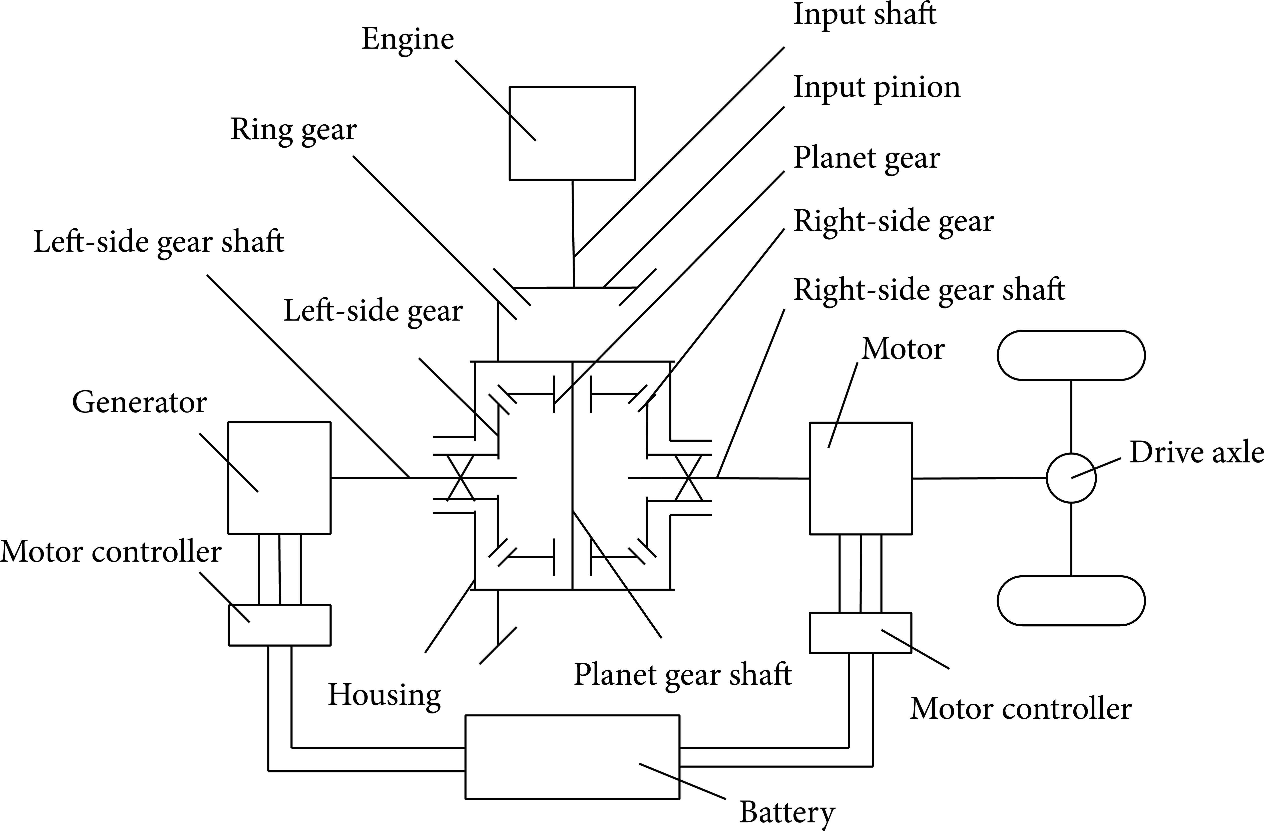
Layout of DPSD in the HEV.
Based on Figure 2, the motion characteristics of the DPSD are as follows [28]:

where ω g , ω e , and ω m are the speeds of the generator, engine, and motor, respectively. T g , T e , T m , and T L represent the torque of the generator, engine, motor, and vehicle load, respectively. k1 is the conversion factor between velocity and motor speed. k represents the teeth ratio of the planet carrier gear and sun gear of a planetary gear set; for the DPSD, k = 1.
Analysis of the relationship among engine, generator, and motor speed leads to the following conclusion. Compared with THS, (1) DPSD requires a generator with larger peak torque; and (2) DPSD allows the generator to have a higher speed, which will not restrict the optimal engine performance during acceleration and will provide a greater degree of freedom to parameter matching of power train [27].
The working mode of planetary-type PSD can be divided into two types: electric vehicle (EV) mode and electric variable transmission (EVT) mode. When the required power, velocity, and state of charge (SOC) are low, the HEV works in EV mode, whereby the engine is turned off and the motor alone drives the vehicle. When the conditions mentioned above cannot be met, the HEV works in EVT mode. The main control goal of EVT mode is to meet the required power, sustain the SOC, and control the engine to work on the optimal working curve simultaneously [28]. In EVT mode, the generator is controlled to manipulate the engine speed, and the motor helps balance the torque requirement [17].
Based on the motion characteristics expressed in (1), the control strategy can be determined as follows.
The engine is controlled to work on its optimal curve. According to the motion characteristics of DPSD, half of the engine torque is used to charge the battery through the generator and the other half is used to drive the vehicle by the motor. The generator speed is regulated by PID to manipulate the engine speed to its optimal curve. Meanwhile, the function of CVT is achievable. The motor is controlled to provide torque to assist the engine as needed and helps the HEV achieve excellent dynamic performance. During the whole working process, motor and generator work intermittently to sustain the SOC.
According to the kinematics analysis, the differential can be used as PSD.
3.2. Analysis on Retrofitting Necessity of the Differential
The differential may be used as PSD according to the motion characteristics mentioned earlier. However, the original structure and strength of the differential may not be appropriate for PSD. Therefore, the possibility of using the differential in the absence of modification requires further discussions.
An HEV simulation model with DPSD was built in ADVISOR [28], as shown in Figure 3. Simulation results in NEDC show that when the differential is used as DPSD, the actual velocity follows the target velocity well and the SOC remains balanced (Figure 4). The speed and torque of each power source are within the normal range (Figures 5 and 6). During the whole NEDC, the speed difference between the two-side gear shafts of the differential, which is also the speed difference between the generator and motor, is continuously large, as shown in Figure 7. Table 1 shows the simple statistics of the speed difference.
Statistics of the speed difference.

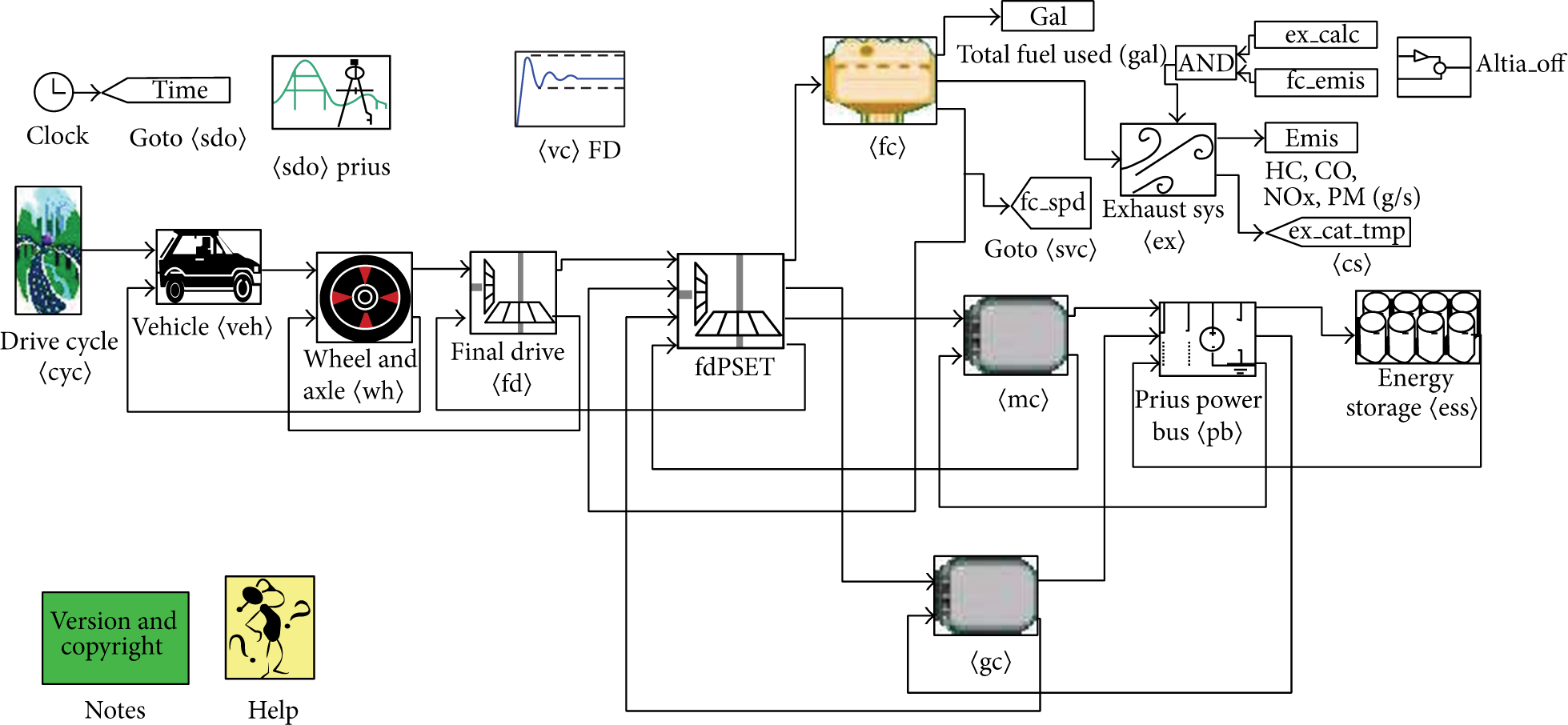
HEV simulation model with DPSD in ADVISOR.

Velocity and SOC in NEDC.
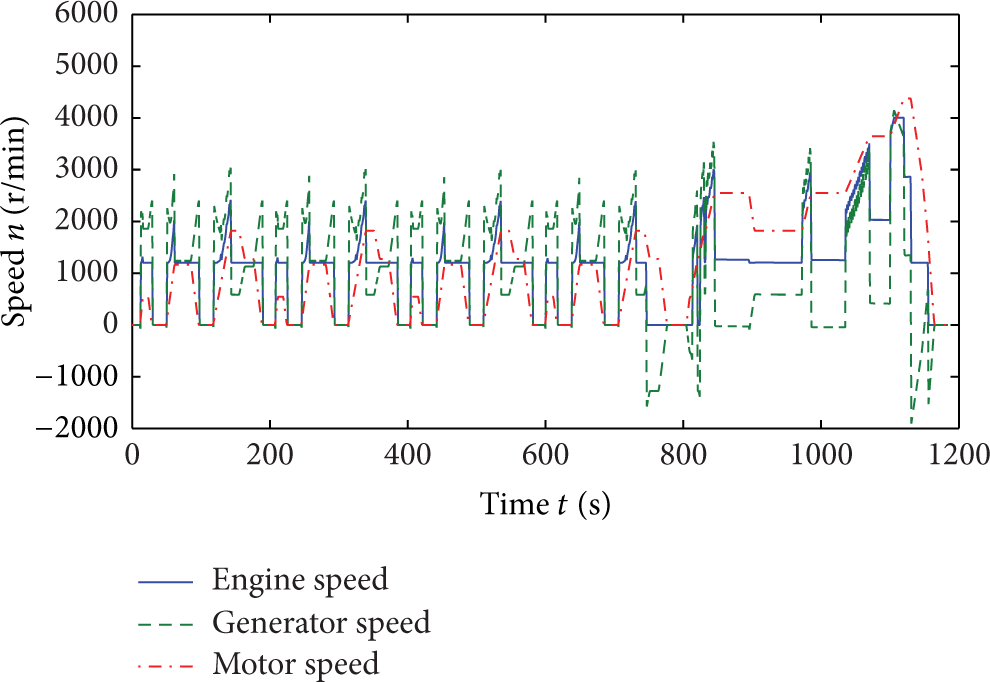
Speed of each power source in NEDC.
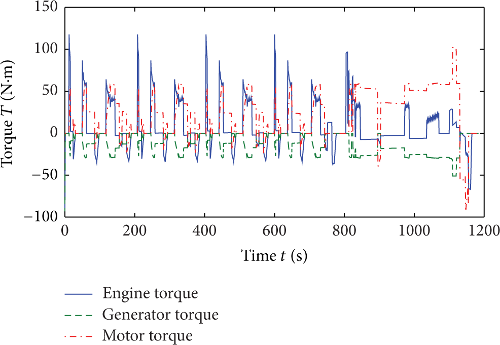
Torque of each power source in NEDC.

Speed difference between two-side gear shafts in NEDC.
When the differential is used in traditional vehicles, the speed difference between the right- and left-side gear shafts is small and its duration is short. Therefore, when differential planet gear and planet gear shaft have direct contact with each other, sliding friction occurs when the planet gear rotates. Slipping is only reduced by putting lubricating oil between the planet gear and the planet gear shaft.
However, according to Table 1, when the differential is used as a PSD in HEVs, the speed difference between the right- and left-side gear shafts is very big, which will lead to the increase of friction power and then cause a severe sliding friction between planet gear and planet gear shaft. Finally, it can result in the failure of the differential. This failure will clearly affect the normal power transmission of the vehicle.
3.3. Retrofit Design of Traditional Differential
To reduce the wear caused by the speed difference between two-side gear shafts when traditional differential is used as PSD, the contact relationship of the planet gear and the planet gear shaft must be retrofitted. A retrofit design scheme that can meet the demand of allowing a sustained large speed difference between the right- and left-side gear shafts is proposed as follows.
Needle bearing is installed between planet gear and planet gear shaft to turn the contact relationship from sliding friction to rolling friction. To install the needle bearing, the structure of the planet gear shaft is redesigned and heat treatment is implemented on its contact surface with the needle roller and the planet gear bore surface to improve surface hardness and avoid indentation [29].
Bearing selection: to ensure the strength of the planet gear shaft, the shaft diameter and needle bearing should be considered before installation. The space between planet gear and planet gear shaft should be limited but must not be too small. The needles of K class needle bearing are independent, which shows that the bearing does not have inner or outer rings and can thus be installed directly. In addition, the bearing needs a small radial space. Therefore, selection of the K class needle bearing is essential (Figure 8).
Design of planet gear shaft: to provide axial positioning for the needle bearing, the original planet gear shaft is redesigned by adding a shaft shoulder. To meet the design requirement, the material of 20MnTi is applied. Meanwhile, partial heat treatment is used on the interface between needle bearing and shaft to increase surface hardness. As the integral differential is used as the prototype of the DPSD, for the purpose of convenient assembly, two sleeves should be installed on both sides of the planet gear shaft, respectively. A pinhole should also be processed on one side of the planet gear shaft and the sleeve mounted on it. Finally, a pin is used to fix the planet gear shaft and the sleeve to the differential housing. Figures 9 and 10 show the redesigned planet gear shaft and the sleeves, respectively. Figure 11 illustrates the fitting components.
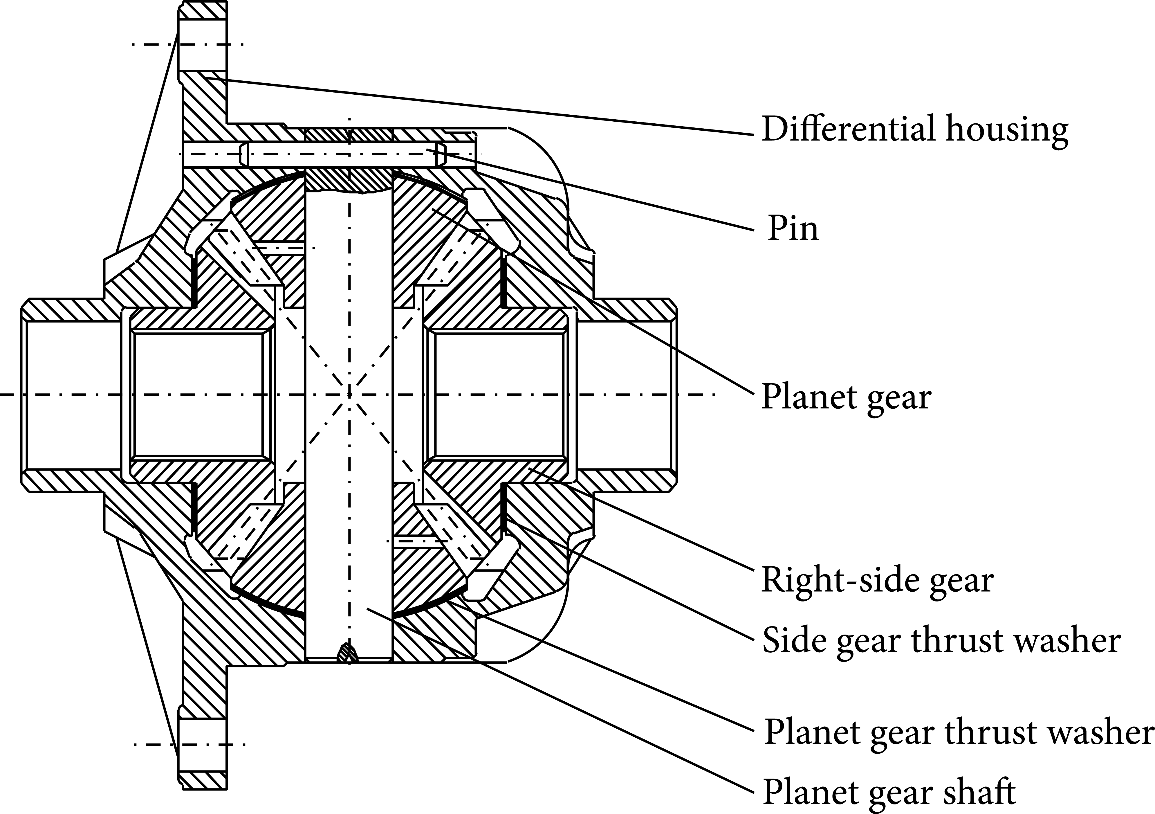
Structure of DPSD: to reduce the cost of the retrofit design, the DPSD uses the original parts and structure of traditional differential except for the two modified parts mentioned earlier. Figure 12 shows the traditional differential used for retrofitting. Figure 13 shows the DPSD structure after the retrofit design.

K class needle bearing.

Redesigned planet gear shaft.
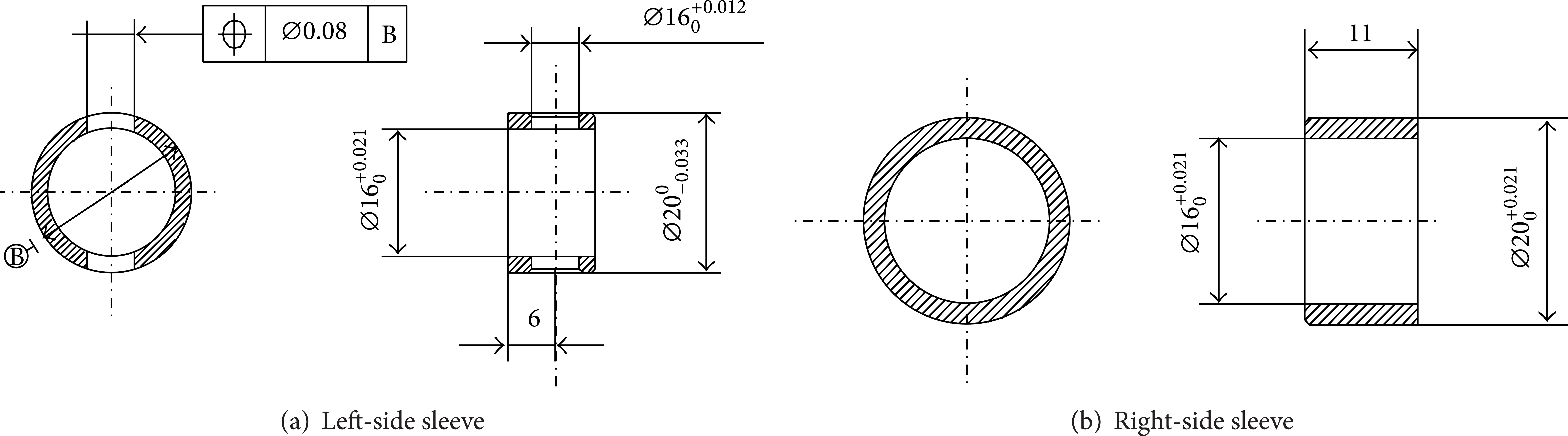
Sleeves.
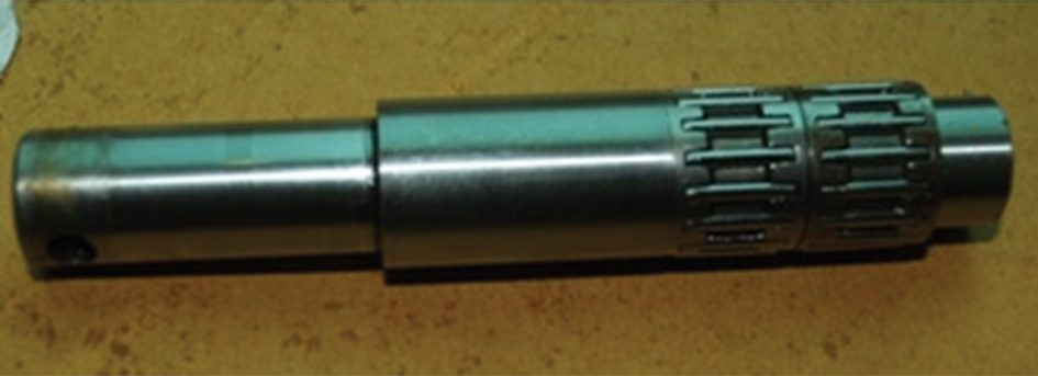
Fitting components of the redesigned planet gear shaft and K class needle bearing.
Traditional differential.

Structure of DPSD.
4. Verification of DPSD
4.1. Simulation Verification of DPSD
First, software simulation is used to verify whether DPSD will become invalid during the NEDC.
A rigid-flexible virtual prototype of the DPSD was built (Figure 14). Finite element analysis was conducted on the planet gear shaft strength and deformation through rigid-flexible cosimulation.
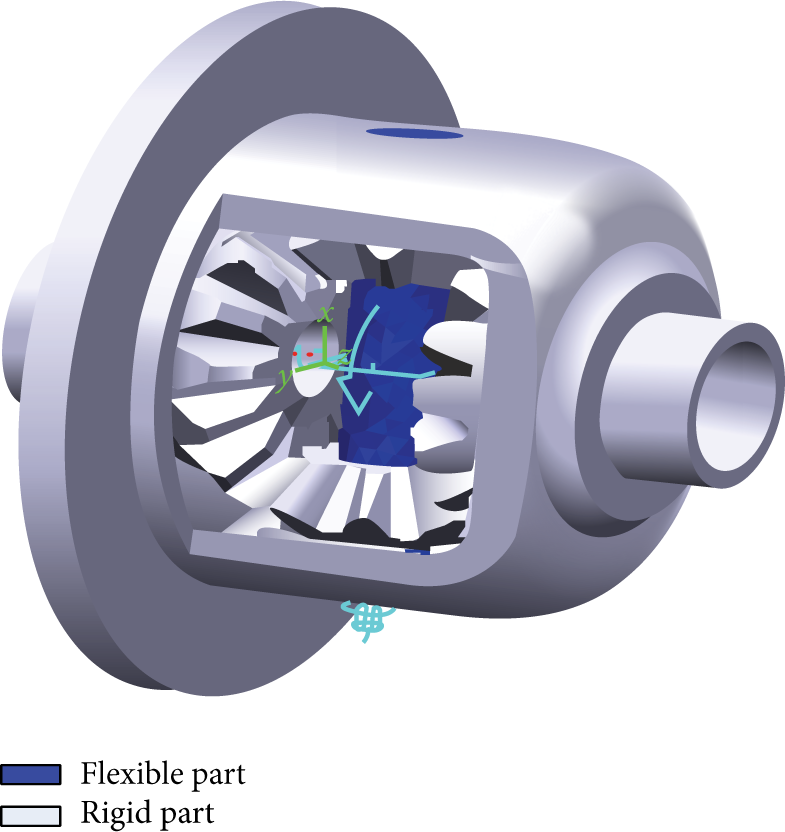
Rigid-flexible virtual prototype of the DPSD.
Table 2 shows the maximum load of the planet gear shaft during NEDC according to the simulation results.
Maximum load of the planet gear shaft during NEDC.

The parameters mentioned in Table 2 were applied to the virtual prototype in the simulation calculations. The simulation results are as follows. Figure 15 shows the stress on the planet gear shaft and Figure 16 shows the strain on the planet gear shaft. According to the results, the maximum stress is 89.9 MPa and the maximum deformation is 0.0058 mm, which are both within the allowable strength and deformation.

Stress on the planet gear shaft/Pa.
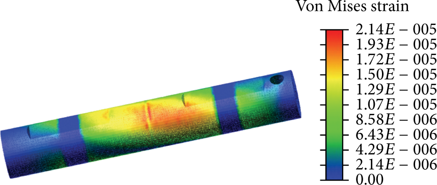
Strain on the planet gear shaft.
Based on the movement characteristics of the DPSD, the speed relationship can be obtained as follows:
where n3 is the rotation speed of the side gear shaft, n0 is the rotation speed of the differential housing rotating around the axle of the side gear shaft, n4 is the rotation speed of the planet gear shaft, Z1 is the teeth number of side gear, and Z4 is the teeth number of planet gear.
When n0 = 1,016, n3 = 4,335, Z1 = 14, and Z4 = 10 are substituted into (2), the result is n4 = − 4,647.
Based on the simulation results during NEDC, the axial force (Fa1) of the planet gear during gear transmission is 517.7 N. Meanwhile, the centrifugal force (Fa2) of the planet gear can be calculated by the following equations:

where m1 is the mass of the planet gear (i.e., 0.151 kg) and r1 is the reference radius of side gear m = 5.4. Total axial force of the spherical washer caused by the planet gear is as follows:

The movement and loading conditions for stress and temperature cosimulation can be obtained based on the maximum load of planet gear shaft during NEDC (see Table 2). The result is shown in Table 3.
Simulation conditions for ABAQUS.

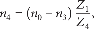
With the help of stress and temperature fields coupled finite element analysis, the stress, strain, and temperature distribution figures of the planet gear thrust washer can be obtained quickly and accurately [30]. Figure 17 to Figure 19 show the simulation results.

Stress on the planet gear thrust washer/Pa.
Figure 17 shows that the stress on most parts of the surface is about 2.45 MPa to 3 MPa; the stress on the inner ring is greater than that on the outer ring and the maximum stress is 4.377 MPa (less than the allowable stress). As shown in Figure 18, the deformation on most parts of the surface is approximately 0.098 mm to 0.19 mm. The relatively large deformation concentrated in the inner ring, which led to an average inner ring deformation of about 0.75 mm but a maximum deformation of below 1.129 mm. Figure 19 shows that maximum temperature, which is approximately 120°C, concentrates near the edge of the thrust washer and that relatively high temperature, which is approximately 100°C, concentrates on both sides of the part with maximum temperature and the inner part of the thrust washer. In Figure 20, the temperature of the planet gear thrust washer is shown to reach its maximum, which is 120.7°C at 4 s, and then stabilizes at around 108°C.
Deformation on the planet gear thrust washer/m.

Temperature on the planet gear thrust washer/°C.

Temperature curve of a node in the highest temperature region.
Simulation results show that maximum stress, deformation, and temperature are all within the allowed values, which means that DPSD will not be abraded to burn eclipse and meets the design requirements.
4.2. Bench Test of the DPSD
To verify further the feasibility of the retrofit design, several typical operating points of the NEDC are selected for bench test.
The Baoke electronic power train test bench is used. The bench is arranged based on the connection relationship shown in Figure 21. The engine is substituted by the main dynamometer; the generator and motor are substituted by number 1 dynamometer and number 2 dynamometer, respectively, as shown in Figure 22.

Layout of the bench test.

DPSD testing bench.
As the speed of the main dynamometer is limited, the bench can be used to test the working condition of the DPSD when the HEV is driving in the low-velocity segment (velocity less than 50 km/h) of the NEDC condition. The program for bench test is shown in Table 4.
Bench test program of the DPSD.

Note: positive torque data represent driving; negative torque data represent driven; positive speed data represent forward; and negative speed data represent reverse.
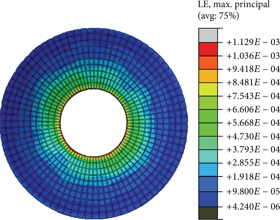
The torque of number 1 dynamometer and the speeds of the main dynamometer and number 2 dynamometer were adjusted according to Table 4. Speed, torque, and temperature of each test point were then recorded. During the bench test, each power source worked in accordance with the esTablished testing program shown in Table 4. The results of the bench test at 15 km/h are shown in Figures 23, 24, and 25, including the speed, torque, and power of the input and output shaft of DPSD. As shown in Figure 25, the internal friction power of the DPSD decreased to approximately 500 W after retrofitting.

Speed of DPSD shafts.

Torque of DPSD shafts.
Power of DPSD shafts.
During the test, the planet gear, planet gear shaft, thrust washers, and other parts of the DPSD all worked smoothly without any acute noise. The conditions of the main parts (Figure 26) were as follows: planet gear shaft was fine without any wear scars or indentation cracks, needle bearing was not curved or broken, side gear shaft and gear thrust washers were undamaged, location pinhole of the left-side sleeve only had a slight deformation, planet gear had a few scratches on the back, and planet gear thrust washers had some abrasions without any failure. Records from the oil temperature regulator show that the oil temperature did not exceed 65°C.
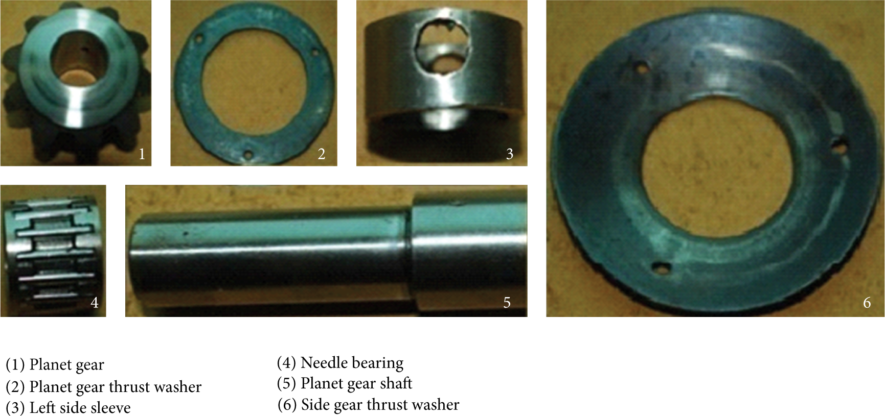
Main parts of DPSD after bench test.
To verify the necessity and advantage of retrofitting further, the same bench test using the original differential was conducted. When the test reached the 15 km/h point, an unusual noise was heard from the differential. Subsequently, the test was terminated and the differential was disassembled. Figure 27 shows that the housing and the planet gear shaft became attached to each other and the planet gear shaft was broken.

Failure of differential after bench test.
The friction powers of the differential and the DPSD at the test velocity of 5 km/h to 15 km/h were compared. After retrofitting, the friction power decreased. This degree of improvement shows an increasing trend as the velocity increased, as shown in Table 5 and Figure 28.
Decreasing internal friction of the differential and the DPSD.

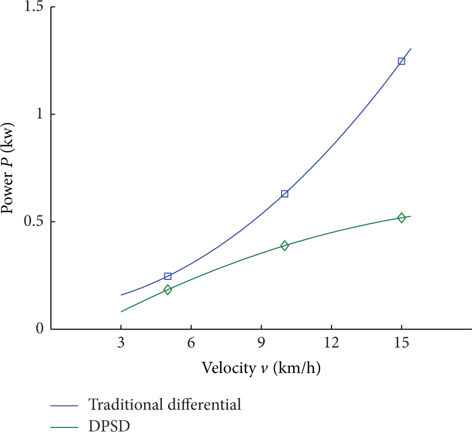
Internal friction power.
The result of the bench test shows that, after retrofitting, the planet gear, planet gear shaft, needle bearing, and thrust washers did not have any major failure. Moreover, retrofitting effectively reduced the friction power of the differential.
5. Conclusions
The present study proposes a new PSD based on the traditional differential for HEV. A retrofit design method including theoretical analysis, software simulation, and bench test is used to design the DPSD. First, the possibility and the necessity of retrofitting are analyzed. Next, a simple retrofit design scheme, including adding a needle bearing and redesigning the planet gear shaft, is proposed. Finally, the rationality of the retrofit is verified by finite element analysis and bench test. Results show that, after the retrofit design, the DPSD can adapt to the torque and speed of every test point of the experimental scheme. At the same time, no obvious signs of failure are observed when the original lubricating oil system is used. In addition, friction power is effectively reduced. Consequently, the feasibility of applying the retrofitted differential as the PSD is verified.
Conflict of Interests
The authors declare that there is no conflict of interests regarding the publication of this paper.
Footnotes
Acknowledgments
This project is supported by the National Natural Science Foundation of China (NSFC no. 51075179 and NSFC no. 51305155) and Scientific Frontier and Interdisciplinary Merit Aid Projects of Jilin University, China (no. 2013ZY08).