
Abstract
Water medium hydraulic systems are widely used in coal mining machinery. As the power of hydraulic system becomes higher, the flow and pressure of water medium relief valve are also higher, and the flow may reach 2000 L/min. However, there is no relevant test-bed which could provide instantaneous high-pressure and high-flow to support the experiment for high-flow relief valve; consequently, this impact test-bed for high-flow water medium relief valve is designed to satisfy fast loading demand. Through building model, simulation analysis, and construction of an impact test-bed of high-flow water medium relief valve, the dynamic performance of high-flow water medium relief valve is detected. The setting pressure of relief valve, the accumulator volume and the filling fluid pressure, and the damping of cartridge valve can be changed, and the dynamic performance of high-flow water medium relief valve under different impact loads is detected. The results show that the designed impact test-bed of high-flow water medium relief valve could provide required high-pressure and high-flow emulsion for the tested water medium relief valve, and it could control the strength of impact load, which is an energy saving, high efficiency, and low cost method.
1. Introduction
There are fewer water hydraulic systems than oil hydraulic systems in the industrial field, and also components that consist of diverse water hydraulic systems have yet to be developed [1]. However, due to the fire resistance and environmental compatibility, using water as the working fluid in hydraulic circuits is receiving increasing attention by both manufacturers and users [2]. In coal mining machinery, the fluid medium, for example, emulsion, has been used in hydraulic systems. The high-flow water medium relief valve refers to the relief valve whose flow is above 100 L/min. When mining coal underground, the original balanced mining pressure isaltered. This may lead to the collapse of main roof rocks naturally. The impact load would be produced when the collapsed rocks impact hydraulic support. Once impact load happened, high-flow water medium relief valve would open within several milliseconds and discharge abundant emulsion; the impact load would drop to its bearable capacity. It is an effective way to prevent hydraulic support destroyed resulting from roof fast-sinking [3]. High-flow water medium relief valve ought to discharge fast when coal seam impact happens. The dynamic performance of water medium relief valve is usually measured by the performance indicators such as opening time, closing time, pressure overshoot, setting time, steady pressure, and dynamic stability.
All the features of high-flow water medium relief valve such as high-pressure and high-flow and using emulsion as working medium cause lots of troubles to test dynamic performance. Therefore, it is necessary to design a specialized experimental system. However, the high-flow water medium relief valve test system, especially dynamic performance test system, is relatively backward not only in theory, but also in practice, far less than the development speed of high-flow relief valve. Currently, there mainly exist 4 test systems of water medium relief valve [4, 5]: (1) high-flow pump fluid-providing system with high cost and energy consumption, which is suitable for small flow valve test only, (2) hammer-dropping impact test system with great bulk and high cost and load disappearing quickly after impact with short duration, which has high requirements for data acquisition, (3) servo hydraulic pressure impact test system with high cost, complex system, and strict demand for hydraulic medium, which is difficult to be applied to the hydraulic component test using emulsion as medium, and (4) blasting impact load system which uses shock wave to complete impact test for relief valve and is not widely utilized in practical use because of its poor controllability.
In this paper a test-bed for high-flow water medium relief valve is proposed which is safe and reliable, affordable, space-saving, and energy-efficient. The test-bed adopts a fast loading mode which takes accumulator as power source, providing the pressure and flow for the high-flow relief valve, which could satisfy the impact experiment condition. The impact performance experiment is completed for high-flow relief valve under the rated pressure 35~50 MPa and the rated flow 0~500 L/min. Finally, the time history of pressure and flow of relief valve is obtained so as to detect whether the water medium relief valve meets the requirements of designed flow and dynamic response performance. The test-bed could detect impact performance of high-flow water medium relief valve and provide instantaneous high-pressure and high-flow emulsion.
2. Working Principle of High-Flow Water Medium Relief Valve
Figure 1 illustrates the structure diagram of the high-flow water medium relief valve. Relief valve inlet is connected with the nether cavity of execution component. When work pressure does not reach opening pressure of relief valve, the spring pushes the spool to the left and the relief valve keeps closed. When emulsion pressure in component is too high, the emulsion would overcome the spring force and drive the spool to move to the right. When the spool holes slide across the position of sealing ring, the emulsion in component would overflow from the relief valve until the column pressure is less than the setting pressure of relief valve.
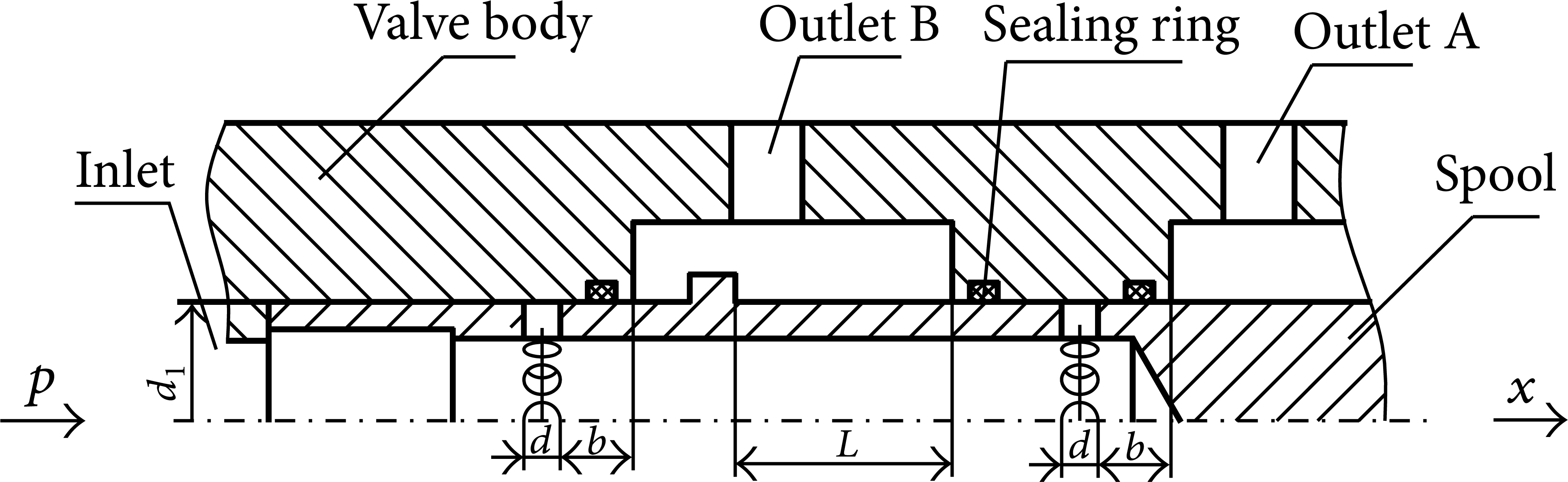
Structure of high-flow relief valve.
3. Relevant Standard Requirements for Dynamic Tests on the Performance of Relief Valves
Depending on the flow, European Standard EN1804-3 [6] puts relief valve into 4 grades (as shown in Table 1) which requires that the pressure in front of valve is 60% of nominal pressure in test. When the flow suddenly feeds the tested valve, the pressure in front of valve should increase to impact pressure p c within 25 ms, and the relief valve should open before reaching the impact pressure p c . The adopted impact pressures p c in the test are 1.55 p n , 1.5 p n , 1.4 p n , and 1.3 p n , respectively.
Required impact test pressure of relief valve of EN1804-3.

p n is the setting pressure of relief valve/MPa.
The items that the test-bed can test are mainly (1) the opening and the closing pressure of relief valve and (2) the impact characteristics of relief valve on impact condition.
4. Mathematic Model and AMESim Simulation Analysis of Test-Bed Hydraulic System
4.1. Mathematic Model of Accumulator
When being impacted, the hydraulic pump stops working. The main role of the accumulator is to provide high-pressure and high-flow hydraulic oil for pressurized cylinder, thus offering the impact to high-flow relief valve. Figure 2 shows a simplified mechanics model of the accumulator which could be divided into gas cavity and liquid cavity. Based on the relationship between pressure and flow of each part, a complete mathematical model of the accumulator is obtained through mechanics model analysis.

Schematic diagram of reservoir accumulator.
In order to simplify the mathematical model of the accumulator, the following assumptions are made.
As the accumulator energy is released fast, the process could be considered adiabatic; compared to gas, fluid owns much greater elasticity modulus, so its compression can be ignored. Under accumulator working condition, the mass of moving section reservoir is smaller than liquid in oil cavity and thus could be ignored. The active area of the gas and liquid cavity is approximately equivalent to the inner circle area of the intermediate cross-section, whose cross-section diameter is d. The flow state of oil in accumulator is laminar flow. Reynolds number of hydraulic oil is less than 2300.
This paper considers the compressive oil in cavity as stressed object whose mass is m a . Without considering the compressibility of oil, its force balance equation is [7]
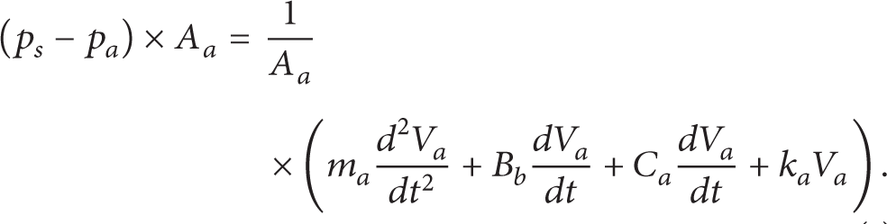
P s : the pressure near oil inlet in the oil cavity, MPa;
P a : the pressure in gas cavity, MPa;
V a : the volume of gas cavity, m3;
A a : the cross-section area of oil cavity, m2;
m a : the fluid mass in oil cavity, kg;
B b : the damping coefficient of fluid;
C a : the damping coefficient of gas;
k a : the stiffness of gas, N/m;
P b : the pressure in liquid cavity, MPa;
P1: the pressure near oil outlet in the oil cavity, MPa.
The equivalent mass is [8]

Here, pa0 is the gas filling pressure of accumulator, V0 is the total volume of accumulator, ρ is the density of oil, and n is the status index of gas.
The damping coefficient of fluid B b is

where μ b is the dynamic viscosity of oil fluid. A b is the high-pressure side area of pressurized cylinder.
The damping coefficient of gas C a is

where μ a is the dynamic viscosity of gas.
The stiffness of gas k a is

4.2. AMESim Simulation Model of Impact Test-Bed
AMESim hydraulic library is used to design various complex hydraulic systems thanks to its powerful function [9, 10]. It can carry out an ideal dynamic performance simulation [11].
The system simulation model is shown in Figure 3.
AMESim simulation model of test-bed hydraulic system.
4.3. Simulation Results and Analysis of Water Medium Relief Valve
The aim of the simulation is to preliminarily verify whether the test-bed could satisfy the relevant standard requirements or not. If it could, then we would carry out further experiment. If not, we should reformulate the test-bed. It is shown in Figure 4 that the solenoid valve gets electricity at 0.1 s. Due to the response speed of the solenoid valve, pilot cartridge valve, the main cartridge valve, and the tested water medium relief valve and the inertia of liquid, the rising of pressure and flow is delayed. The pressure in front of relief valve begins to rise at 0.127 s, and it rises to 429 bar at 0.134 s; meanwhile the flow begins to rise as well. The pressure rises to a maximum of 585 bar at 0.141 s and the flow is 646 L/min at that moment. The flow reaches a maximum of 675 L/min at 0.143 s. Then both of the pressure and flow attenuate. The calculation shows that the required time for the prefilling fluid pressure to rise to the peak value is 14 ms and that the required opening time of relief valve is 8 ms, which satisfy the European Standard EN1804-3 requirements on the impact performance of relief valve.

Simulation results for pressure and flow after relief valve opening.
5. Experiments and Discussions
5.1. Test System
The test is accomplished on the impact test-bed for high-flow water medium relief valve. The test-bed is designed referring to the standard EN1804-3 and GB25974.3-2010 test requirements, which could complete high-flow water medium relief valve impact test on rated pressure 35~50 MPa and rated flow 0~500 L/min. The test-bed takes accumulator as power source in fast loading mode, which could provide high-flow water medium relief valve with required impact pressure and flow. Moreover, the test-bed could simulate working condition when bearing different impacts and examine features of pressure and flow of the tested water medium relief valve under different impact conditions.
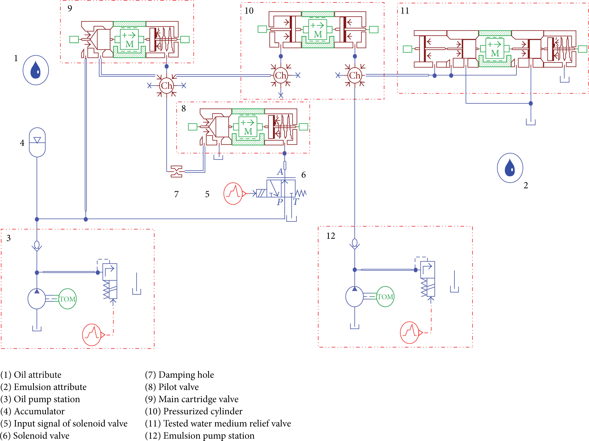
A small flow oil pump provides fluid to accumulator as shown in Figure 5. When the pressure of accumulator reaches the setting filling fluid pressure p2, the pilot valve group starts moving, and the pressure of cartridge valve upper end drops and then cartridge valve opens quickly. With pressurized cylinder supercharging, emulsion in relief valve overflows. The FAD500A high-flow relief valve, whose nominal flow is 500 L/min and setting pressure is 40 MPa, is selected as a tested valve to verify whether the designed test system could satisfy the high-flow impact test or not.

Hydraulic system of high-flow relief valve impact performance test-bed.
5.2. Performance Indicator
The volume of test-bed accumulator is adjusted to V0 = 80 L and the filling fluid pressure to p2 = 22.4 MPa, and then impact test on relief valve is carried out. The results are shown in Figures 6 and 7.
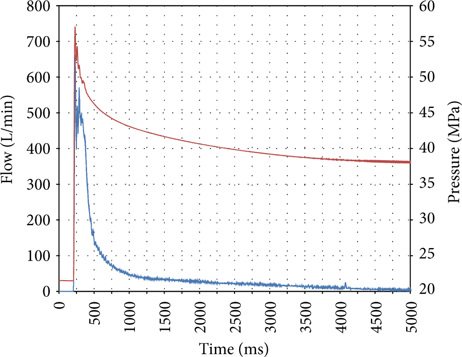
Pressure and flow test curves of the relief valve.

Pressure and flow test curves of the relief valve at the moment of opening.
Figures 6 and 7 illustrate that the pressure in front of the relief valve is 21.6 MPa before being impacted. Timing the pressure in front of relief valve when it begins rising, 20 ms later, it reaches the peak pressure 57.4 MPa (1.425 p n ) with corresponding relief valve flow of 375 L/min. When the fluid discharged from the accumulator, the pressure presents a process which keeps shocking and attenuating. When the pressure drops to 40 MPa, the corresponding flow is 22 L/min. The relief valve flow begins to rise after 6 ms; it rises to peak flow 645 L/min after 31 ms. The pressure reduces to 38 MPa after 5000 ms; when the flow is zero, the relief valve is closed. From the two figures we can obtain performance indicators of the tested relief valve.
5.2.1. Unloading Flow
The test indexes of high-flow relief valves are different from those of common relief valves. The test system is loaded by accumulator whose filling fluid pressure declines with emulsion overflow, and the pressure and flow are unstable. However, as shown in Figure 7, within 150 ms (corresponding to 210 ms~360 ms) the pressure and flow curve of relief valve almost fluctuate around a straight line after impact. In order to eliminate the influence of pressure-decreasing and flow-decreasing of accumulator to the test, the peak pressure and peak flow at corresponding moment on the straight line are defined as steady pressure and steady flow, respectively. The steady pressure is 53.9 MPa and the steady flow is 490 L/min. To a large extent, the steady flow reflects the unloading capacity of relief valves.
5.2.2. Rise Gradient of Pressure
Rise gradient of pressure is the slope of point (214 ms, 25.8 MPa) to point (222 ms, 53.9 MPa) in Figure 7. Calculation result is

It totally satisfies the impact test requirements for high-flow relief valve.
5.2.3. Sensitivity
Sensitivity could be tested by pressure rise-time, opening time, and flow rise-time which are 20 ms, 6 ms, and 25 ms, respectively, in the test. The opening time is none other than prescribed by the standard EN1804-3. The test value 6 ms is far less than the standard value 25 ms indicating that the tested relief valve is much more sensitive. It is noticed that when the flow begins to rise, the corresponding pressure is 38.2 MPa, which does not reach the setting pressure of the relief valve (40 MPa). The reason is that the oil compressibility makes cylinder move before the relief valve opens, resulting in flow rise ahead of time. However, the motion state truly reflects the rule of hydraulic cylinder under impact load, which is consistent with simulation results.
5.2.4. Stability
Stability can be tested by pressure overshoot and flow overshoot. Pressure overshoot of impact test in Figure 7 is defined as follows:

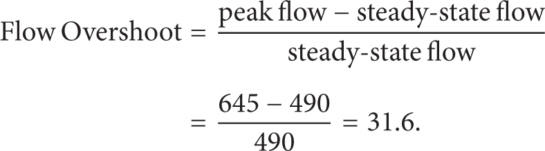
The flow overshoot of impact test is shown as follows:
The number of pressure oscillations is 5.
Maximum amplitude is 57.4 − 52.5 = 4.9 MPa.
5.2.5. Closing Pressure
As mentioned in Figure 6, the closing pressure of the relief valve is 38.0 MPa, which is equal to 95% of the nominal pressure, satisfying minimum requirements of the GB 25974.3-2010 that “the closing pressure should not be less than 90% of nominal pressure.”
5.2.6. Effects of Relief Valve Setting Pressure p n on Experiment Result
By changing pressure-adjusting spring of high-flow relief valve, the opening pressures are set at 35.8 MPa, 44 MPa, and 48.3 MPa, respectively, and the fluid pressure at the accumulator is set at 19.7 MPa, 24.6 MPa, and 26.9 MPa, respectively. Flow and pressure curves of test are shown in Figure 8. The response data of the relief valve under different setting pressures can be seen in Table 2. It can be concluded from Table 2 that the setting pressure of relief valve determines its steady performance (opening pressure, peak pressure, and closing pressure), but it has little effect on the flow characteristics (steady flow and flow overshoot). What is more, it almost has no effect on the response speed of relief valve (pressure rise-time, flow rise-time, and opening time).
Response data of relief valve under different setting pressures p n .


Response curves of relief valve under different setting pressures p n .
6. Influences of Key Parameters on the Characteristics of Test-Bed
In order to investigate the effects of accumulator volume V0 and filling fluid pressure p2 on the impact results, relief valve opening pressure is set at 40 MPa. Change V0 and p2 and carry out impact test on FAD500A high-flow relief valve.
6.1. Effects of Accumulator Volume V0 on Experiment Result
The volume of accumulator V0 is adjusted to 40 L, 80 L, and 100 L, respectively, and fluid filling pressure p2 to 22.4 MPa (1.4 p n ). The changes of the flow with time history under different volumes of the accumulator are shown in Figure 9. The data shows that discharging capacity of the accumulator and overflow time of the relief valve both increase with volume V increasing. When V0 is set to 100 L, overflowing time is much longer than that of 40 L and 80 L (from 225 ms to 375 ms). The flow of the relief valve does not appear to increase significantly, and response time is scarcely influenced. That is because the instantaneous peak flow of the relief valve and the response time mainly depend on the filling fluid pressure, opening degree of the spool, and internal structure of the valve body and have nothing to do with the total gas volume of accumulator.

Response curves of relief valve under different volumes V0 of accumulator.
6.2. Effects of Accumulator Filling Fluid Pressure p2
The filling fluid pressure of the accumulator p2 is adjusted to 20.5 MPa (1.3 p n ), 22.4 MPa (1.4 p n ), and 24 MPa (1.5 p n ), respectively, and the volume V0 to 80 L. It is shown in Figure 10 that the experimental curves of the pressure and the flow vary with time. Table 3 illustrates the data of results analysis. It can be concluded from the data that the flow and pressure of relief valve both significantly increase with filling fluid pressure p2 increasing. When p2 is 24 MPa, the stable time of overflowing has also been prolonged, yet the response time does not change obviously. It reflects the actual working state of the relief valve under different impact load as well.
Response data of relief valve under different setting pressures p2 of accumulator.

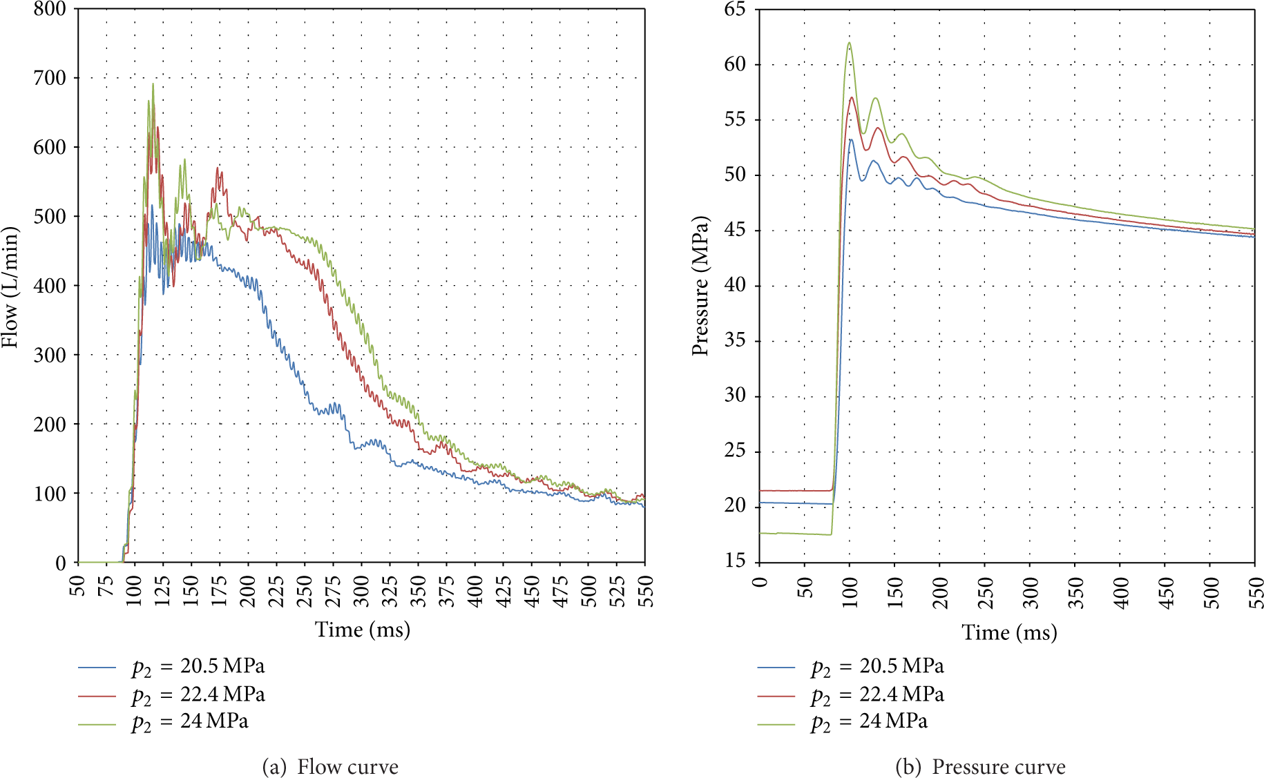
Response curves of relief valve under different setting pressures p2 of accumulator.
This is mainly because the increase of p2 results in the increase of inlet pressure of the relief valve, with the corresponding flow increasing. Meanwhile, because of the enlargement of the peak pressure and peak flow, the hydraulic impact becomes fiercer. Therefore, the oscillation is relatively more obvious and the stabilization time becomes longer. Similarly, the response time has nothing to do with the filling fluid pressure but the structure of the tested valves.
6.3. Effects of the Openness of Throttle Valve
In the test, variable damping in cartridge valve group is set through adjusting throttle valve. The cycle numbers of twisting the throttle valve's knob counterclockwise are defined as n. When one-way throttle valve is fully closed, n = 0. We, respectively, set n = 0.5, n = 2, and n = 4, accumulator volume as 80 L, the corresponding filling fluid pressure as 22.4 MPa, and the relief valve setting pressure as 40 MPa.
The pressure and flow curves of impact test are shown in Figure 11. It can be concluded that, with the increase of the openness of the cartridge valve damping, the response speed of the flow and the pressure accelerates, the flow overshoot increases, and the pressure fluctuation rises, resulting in more violent impact on the relief valve. It indicates that the response speed of cartridge valve has a direct influence on that of the flow and pressure of relief valve, yet it has little effect on steady-state value of flow and pressure.

Response curves of relief valve under different dampings n of cartridge valve.
As the response speed of cartridge valves is relatively faster, the response time of whole test system becomes shorter, making the response speed of the tested valves faster and making the flow through cartridge valves larger.
7. Conclusion
In this paper, a test-bed for high-flow relief valve is designed. Then the dynamic performance of relief valve is detected. Through changing the key indicators, such as the setting pressure of relief valve and accumulator volume, filling fluid pressure, and damping of cartridge valve group, the dynamic performance of high-flow relief valve is tested under different impact load conditions. The result indicates that the designed test-bed is able to provide high-flow emulsion that the impact experiment of relief valve needs and to control the strength of impact load. Meanwhile, it is an energy saving, high efficiency, and low cost way of testing a high-pressure and high-flow hydraulic component. The designed fast loading system which puts accumulator as power source takes the place of high-pressure and high-flow hydraulic pump. In practice, this test-bed can not only test the high-flow relief valve, but also provide a method of providing instantaneous high-pressure and high-flow emulsion.
Conflict of Interests
The authors declare that there is no conflict of interests regarding the publication of this paper.
Footnotes
Acknowledgments
This work is supported by Key Projects in the National Science and Technology Pillar Program during the Eleventh Five-Year Plan Period (2009BAF41B00) and Specialized Research Fund for the Doctoral Program of Higher Education (20130095110012).