
Abstract
Continuous injection direct rolling (CIDR) combined intermittent injection and rolling process is a new technology for molding optical polymer plates with microstructured patterns; research on forming PMMA optical plates is an aspect of it in this paper. The equipment of CIDR process consists of plastic injection module, precision rolling module, and automatic coiling module. Based on the establishing mathematical CIDR models, numerical analysis was used to explode the distribution of velocity, temperature, and pressure in injection-rolling zone. The simulation results show that it is feasible to control the temperature, velocity, and injection-rolling force, so it can form polymer plate under certain process condition. CIDR experiment equipment has been designed and produced. PMMA optical plate was obtained by CIDR experiments, longitudinal thickness difference is 0.005 mm/200 mm, horizontal thickness difference is 0.02/200 mm, transmittance is 86.3%, Haze is 0.61%, and the difference is little compared with optical glasses. So it can be confirmed that CIDR process is practical to produce PMMA optical plates.
1. Introduction
Polymer plates with microstructure patterns have been widely used in various fields such as light guide plate (LGP) in LCD display, microfluidic chip, and optical fiber communication, and so on. There are different approaches for the fabrication of these optical components with microstructures, including injection-compression molding, hot embossing, and laser processing [1, 2]. Although optical components of small size can be produced by injection-compression molding method, the method is not suitable for producing large-sized and thin ones due to the residual stress [3, 4]. Hot embossing is limited by the difficulty in controlling the uniformity of microstructure patterns, so it is difficult to replicate large-area microstructure [5]. Laser processing has strict requirements for precision of machine tool, which is expensive and has slow processing speed; thus this method is only suitable for piece production [6]. So how to ensure the quality of polymer plates, how to improve production efficiency, and how to lower production cost are an important subject for the current research in which urgent breakthrough is required.
In view of the above problems, this paper presents the development of novel integrated roll-to-roll embossing process named continuous injection direct rolling (CIDR) for polymer optical plates with microstructure patterns [7]. The technology combining injection molding and rollers embossing, injection-rolling molding cavity, and rolling technology are applied to form optical thin plates, then it copies the microstructure on rollers to the two surfaces of the plates, so it can realize the continuous forming to optical plates and its microstructure. In the process, the two main problems should be solved: one is thickness difference, plate shape, and optical performance of polymer plates; the other is precision and uniformity of microstructure. This paper mainly focuses on the effects of temperature field, velocity field, and injection-rolling force field on the thickness difference, plate shape, and optical performance of polymer plates.
This paper firstly illustrates the composition of CIDR process equipment and the forming mechanism and presents some key technologies related to the development of CIDR process. Then the mathematical models are setting up including distribution of velocity, temperature field, and injection-rolling force. Through the simulation analysis of the CIDR process, the equipment can meet the forming condition for PMMA plate. Finally, experiments have been done, and PMMA optical plates of good quality are produced, and the CIDR process is proved to be feasible to produce PMMA optical plates.
2. Continuous Injection Direct Process
As shown in Figure 1, the conceptual framework for the CIDR process consists of three parts which include plastic injection module (PIM), precision rolling module, (PRM), and automatic coiling module (ACM). There is injection-rolling nozzle designed in PIM to ensure that melting material flowing into injection-rolling mold cavity has homogeneous velocity and certain temperature in the flow direction. The assembly injection-rolling nozzle and down roller are shown in Figure 2 [8]. The arc faces in the front of the lips of injection-rolling nozzle have the formation of concentric with the surface of rollers, and the arc faces in the front of the sidewalls of injection-rolling nozzle have the formation of concentric with annular groove of rollers. So the front faces of the lips and the medial faces of the sidewalls of injection-rolling nozzle and the surface of rollers constitute the injection-rolling mold cavity. When the polymer plate is brought out of the gap under the effect of injection force and friction force, injection-rolling cavity has become a confined cavity in this moment.

CIDR system configuration.

The assembly schematic diagram of injection-rolling nozzle and down roller.
The material forming mechanism in CIDR is shown in Figure 3. Melting material is injected into injection-rolling nozzle in PIM and then enters the injection-rolling cavity in an evenly proportioned velocity and temperature through the shunting action of the injection-rolling nozzle. When the melting material touches the cold rollers, it changes from melting state into rubbery state and then into glasses state as the heat exchanges with rollers. The material in the injection-rolling zone is compressed and deformed. Through the rolling effect of rollers, the mass density of the thin plate is guaranteed; as a result polymer plate in superior quality is obtained. The CIDR of the polymer plate changes intermittent slip casting into continuous injection-rolling. Meanwhile, it carries out-rolling compression molding of the polymer material in the injection-rolling zone, and the polymer plate is separated from the roll gap under the effects of roll friction force; this process properly applies the injection-compression process into the continuous production of polymer plates.

PMMA plate forming mechanism in CIDR.
3. Model and Assumptions
3.1. Injection-Rolling Force and Velocity Modeling
The whole injection-rolling zone is divided into three zones, as shown in Figure 4. ABCD is injection zone, BCFE is rolling zone, and EFHG is elastic recovery zone.
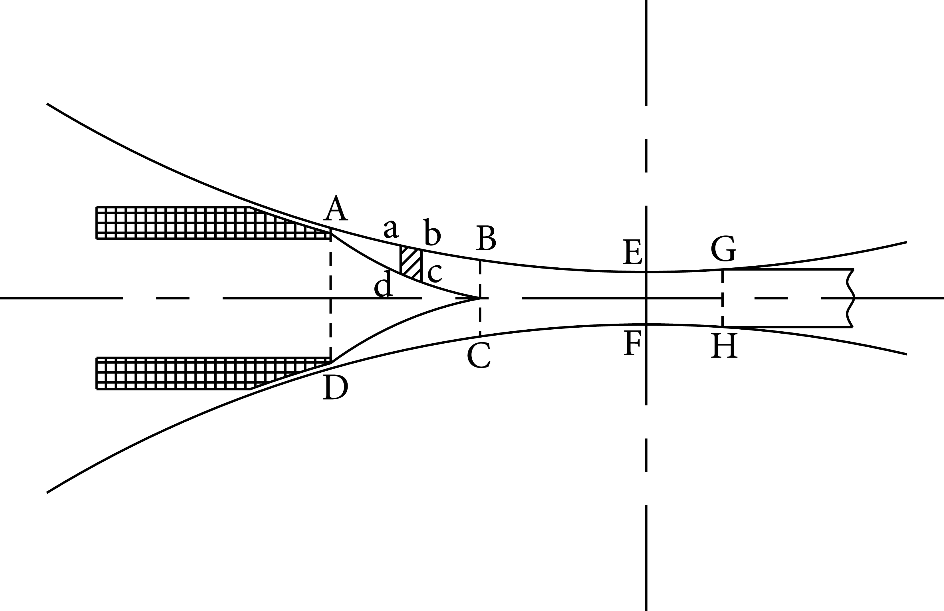
Injection-rolling zone divided three zones.
In injection zone, melting materials are cooled and turned into rubbery state and filled into the whole zone, so the rolling force mainly comes from injection force in the zone. It is therefore to consider element high elastic state materials in the area abcd as the research object to establish the equilibrium differential equation. The force diagram of the element is shown in Figure 5; P x is the stress from the roller, τ x is the friction stress from the roller, P i is the component stress from the injection stress, and σ x is the stress between the elements. Materials in injection zone may be regarded as uniform velocity; the microelement is in the state of equilibrium, so the whole force acting on the microelement is zero, and the force equilibrium equation can be established in the vertical direction. Consider the following:


Force analysis of microelement in injection zone.
Equation (1) is simplified

Set the injection stress as P, so P i can be obtained from the following equation:

According to Coulomb's law of friction, τ x can be obtained as follows:

where μ is coefficient of friction.
According to (2), (3), and (4), the rolling force in injection zone can be obtained as follows:

where w is the width of PMMA plate and L is the length of contact arc, which is calculated from the following equation:

where ΔH is induction, which is equal to the height difference between A and B.
Figure 6 is the schematic cross-sectional area of the rolling and elastic recovery zone. Two rollers separated by the polymer plate of a viscoelastic fluid are rotated in the same direction. Each roller has a radius R, rotating with a linear constant velocity v. The minimum gap half-height, H0, is such that H0≪R. The one-half exiting plate thickness is represented by H2.

Schematic diagram of rolling and elastic recovery zone.
According to the geometrical relationship of the roller surface arc equation, we can obtain the expression of the H(x) at any cross-section thickness. Consider the following:

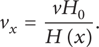
Because the polymer plate produced is thin, rollers’ radius is much larger than the average thickness of the injection-rolling zone. Ignoring the y-direction flow rate of material, then v y = 0; so in the injection-rolling zone, the flow of the polymer is symmetrical to the x-axis, and the flow velocity should be equal to each cross-section, so any cross-section flow velocity v x can be obtained by the following equation:
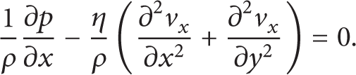
In the rolling zone, polymer is in viscoelastic fluid state and mainly affected by the rolling force; therefore, Navier-Stokes equations used as the basic equations to research the rolling force and velocity [9, 10]

where p is fluid pressure, F is volume force, ρ is density, η is viscosity, and v i is x, y, z components of the velocity.
According to the characteristics CIDR process, some assumptions can be made [11].
At the roller's axial direction, temperature, velocity, and force of polymer material are all consistent, and deformation perpendicular to the axial plane deformation of rolls is only in x-y plane, so v z = 0.
Ignoring the inertial force and the volume force, so F i = 0, and dv i /dt = 0.
Polymer material in injection-rolling zone is considered to be a viscoelastic fluid and satisfies the incompressibility condition.
There is no relative slide between polymer and rollers, and they contact tightly.
The deformation heat and friction heat in injection-rolling zone are negligible.
Based on these assumptions, the Navier-Stokes equation can be simplified as follows:
Putting (7) into (10), the unit pressure model of melting zone rolling is as follows:

In rubbery state, viscosity is generally calculated by the W-L-F equation [12]

where T is absolute temperature, T g is glass transition temperature of PMMA, and η g is viscosity at glass transition temperature.
According to (11), the formula used to calculate rolling force in rolling zone can be obtained [13]
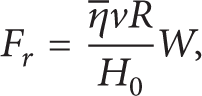
where
The force of elastic recovery zone is small compared with other zones, and it can be neglected. So the total injection-rolling force in injection-rolling zone can be obtained as follows:

3.2. Temperature Distribution Modeling
In order to analysis the optimum forming temperature of the PMMA plate, thermodynamics experiments of viscoelastic were carried on for PMMA. The equipment used was the dynamic mechanical analyzer (DMA). Because the low frequency is equivalent to static, so we chose a frequency of 1 Hz. The test results are shown in Figure 7. Curve 1 is storage (elasticity) module, curve 2 is loss modulus, and curve 3 is loss factor. The above parameters are reflected with temperature. During hot deformation of the polymer, elastic modulus reflects the springbuck characteristics of the material. The smaller the elasticity module value is, the higher the resistant rate is. Loss modulus reflects the viscous material deformation ability; the greater it is, the larger the viscous deformation is, and its peak is the glass transition temperature. Loss factor is the ratio of loss modulus and elasticity module, and it is a comprehensive amount of viscoelastic; the greater it is, the greater the total amount of permanent deformation is.

PMMA's viscoelastic property change with temperature.
As can be seen from Figure 7 that the temperature range from 110°C to 130°C is the optimum forming temperatures, and the material is in rubbery state. The material temperature of the minimize roller gap should be controlled below 110°C.
Temperature is an important process parameters, and it has a great effect on the CIDR process. To calculate the injection-rolling force, the temperature distribution in the zone needs to be calculated. In the zone, the flow condition of the polymer and the temperature distribution is complex, which is multifield coupling issues; the temperature distribution will change with random process parameters. Due to the fact that the temperature of the injection-rolling zone is difficult to measure, we can analysis the temperature changes on certain assumptions premise. Because the temperatures change of the polymer material is mainly caused by heats transferring to the rollers, the rollers’ diameters are much larger than the height of injection-rolling zone. It can be assumed that the average temperature of the injection-rolling zone along the rolling direction is linear distribution, which is shown in Figure 8.
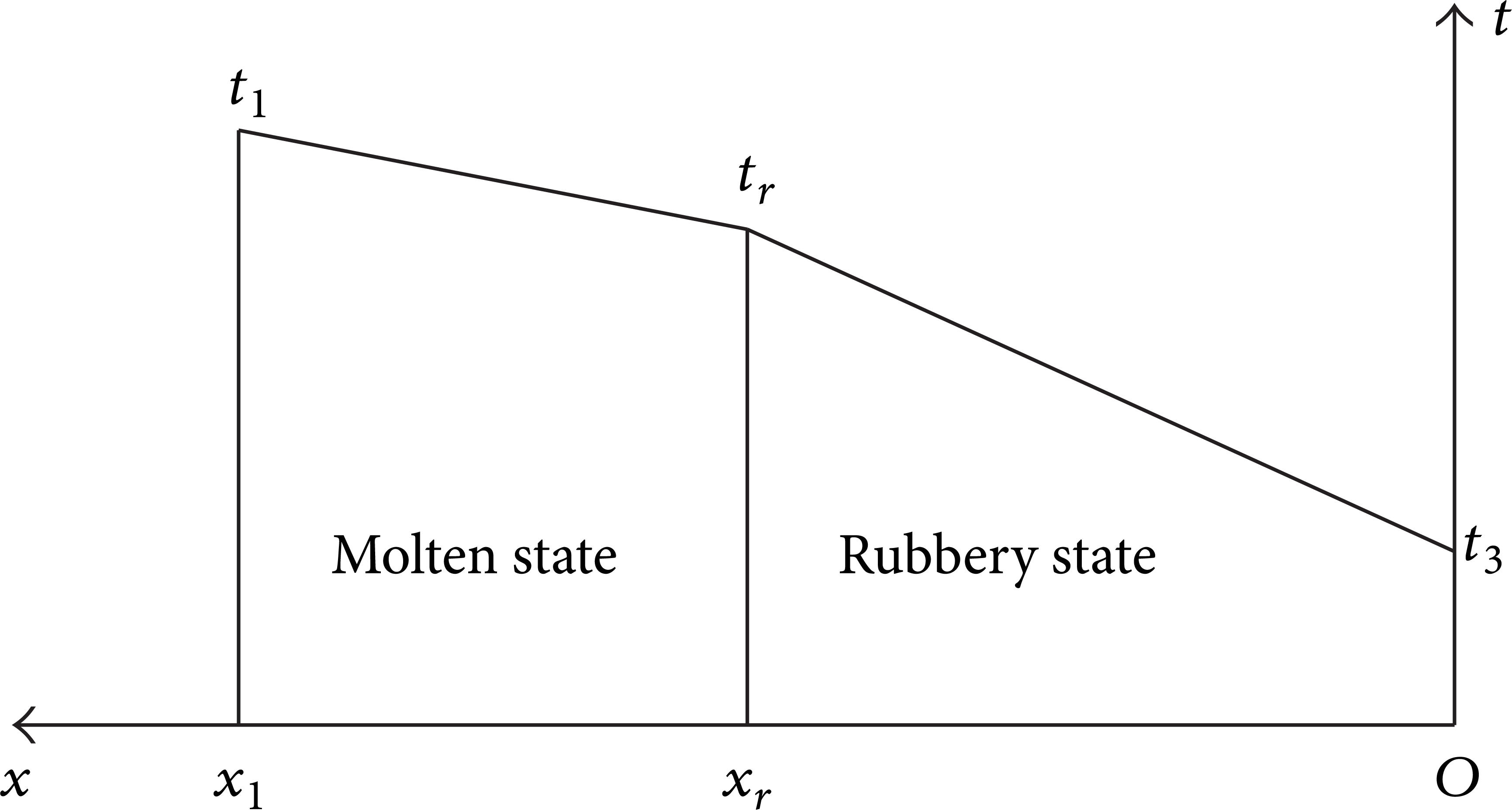
Temperature distribution in injection-rolling zone.
The temperature distribution equation of polymer in injection-rolling zone can be obtained according to Figure 8. Consider the following:
where in melting zone: a = (t1 − t r )/(x r − x1) and b = (x r t1 − x1t r )/(x r − x1); in rubbery zone: a = (t r − t3)/x r and b = t3.
In (15), t1 is the temperature of the melting material when it is injected into the molding cavity from the injection-rolling nozzle; t r is the temperature of rubbery state transition point; t3 is the out-rolling temperature which must be in rubbery. According to the characteristics of the PMMA material and the analysis of the optimum forming temperature, t1, t r , and t3 can be determined. x1 is the length of the injection-rolling zone, which is determined by the distance between the injection-rolling nozzle and the roller. x r is the position of the rubbery state transition point, if the injection velocity is given; then x r is determined by the velocity of the heat transfer from the polymer material to rollers. If the heat transfer rate is fast, the range of the melting zone is narrow, and vice versa. Since the rest parameters in (15) are the fixed value, so the value of the x r can be calculated through the heat conduction equation for injection-rolling zone conducted by finite element analysis.
4. Simulation Analysis of CIDR
CIDR process for PMMA optical plate is a complicated process of thermomechanics coupling, and the temperature and velocity of the material in injection-rolling molding cavity are difficult to measure. Therefore, it is necessary to simulate and analyze the whole process of CIDR in order to obtain the optimum technological parameters and provide reference for experiments. In addition, the whole process should obey the law of conservation of mass, the law of conservation momentum, and the law of conservation energy. The laws together with the already built temperature distribution, velocity, and injection-rolling force model are the control model of the CIDR process [13].
First of all, the flow of melting material in the injection-rolling nozzle was simulated in order to ensure that the melt polymer is injected into injection-rolling molding cavity at uniform velocity, and the result is shown in Figure 9. From the velocity distribution above, it can be seen that melting material flows into the nozzle evenly through a tube, and then the first speed adjustment begins in the first half of runner. Melting material diffuses to both sides gradually after entering the runner and the velocity of melting material in the middle is fast, which then decreases little by little. On the contrary, the velocity of material near both sides is slow, but then it increases. The second speed adjustment of the fishtail-like structure begins in the second half of the runner. The main purpose of the second shunt is to make the velocity of the melting material become more uniform, so the melting materials flow into the molding cavity at uniform velocity.
Velocity distribution in injection-rolling nozzle.
In the injection-rolling molding cavity, the flow temperature, velocity, and stress are uniform in the direction perpendicular to the flow direction according to the above hypothesis, so the cross-section of the injection-rolling molding cavity perpendicular to the rollers can be used as the research object. The geometry model and boundary conditions are shown in Figure 10.

Geometry model.
Simulation conditions of CIDR process for PMMA are shown in Table 1.
Simulation conditions of CIDR process for PMMA.

The cloud chart of temperature is shown in Figure 11, in which the temperature at rollers’ gap (H0) is close to the temperature at glass transition point, and it is the optimum forming temperature for hot embossing, which indicates that melting material may be cooled in certain time because of the heat conduction from material to rollers and make the plate formed at the optimum temperature. The temperature of the material at out-rolling (H2) is lower than the temperature at glass transition point. So the CIDR process is in accordance with the law of the state change of the material.

Cloud chart of temperature.
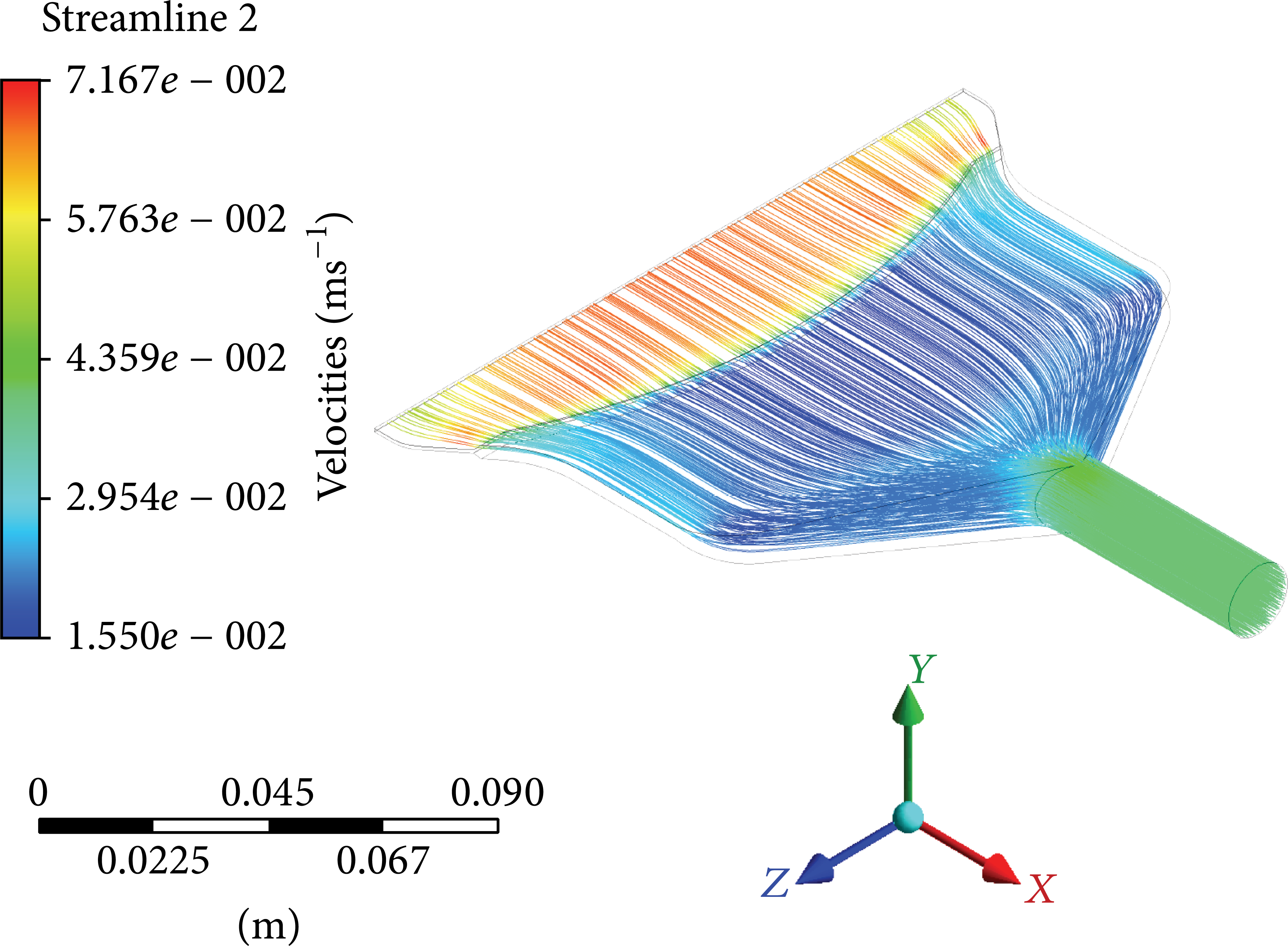
Figure 12 is comparison between model temperature and simulation temperature in injection-rolling zone, which shows that they have good coincidence degree.
Comparison between model and simulation.
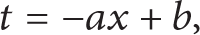
Figure 13 is the cloud chart of velocity change. As can be seen from the chart, because rollers’ gap turns small, flow velocity at rollers’ gap (H0) is the largest in the whole process. Section velocities keep uniformity at the section of separation (H2), because material has been solidified at glasses state.

Cloud chart of velocity.
Figure 14 is the cloud chart of pressure on material; the maximum pressure is not at the smallest rollers’ gap (H0) but at the previous section, which is beneficial to the forming of material, and it is the same with the simulation result in the paper [9]. At the point of separation (H2), the force direction is opposite to that in the injection-rolling zone, due to the recovery of elasticity. Plate density can be ensured under persistent pressure in the whole process. So the CIDR process is feasible for PMMA plate according to the simulation results.
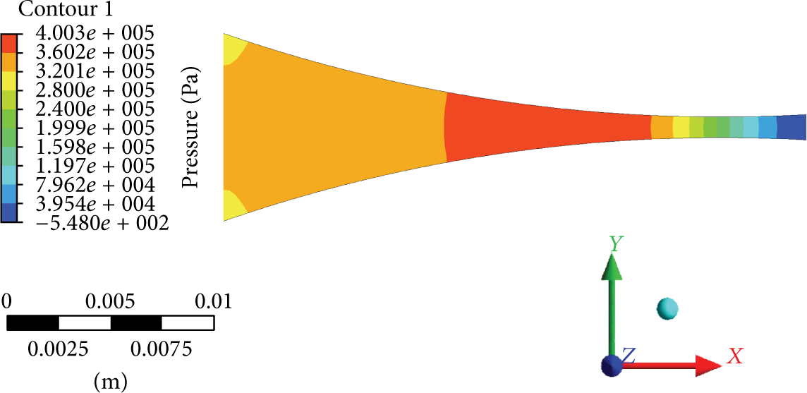
Cloud chart of pressure.
5. CIDR Experiment and Analysis
CIDR experimental equipment is shown in Figure 15. The main parts of the equipment include injection machine, injection-rolling machine, and coiling machine, and other auxiliary parts include cooling water tower, cooling machine, and annealing box. As can be seen from Figure 15, the whole production line is shortened compared with extrusion-calendaring equipment, which reduces the production cost and saves the production time.

CIDR experiment equipment.
Materials used in experiments are PMMA pellets made in QiMei Company in TailWan. Experiment process can be described as follows: put the PMMA dried pellets into the material cylinder and transport them to injection-rolling nozzle after being heated to about 220°C through rotary screw then inject them into injection-rolling cavity after the second shunt; then they would be transported forward under injection force and the friction force of two counter rotating rollers and the plate is formed during the process under the effect of rolling force and cooling of the rollers; at last the plate is coiled by traction rollers and coiling roller after passing through annealing box, and a production line of the thin PMMA plate is formatted.
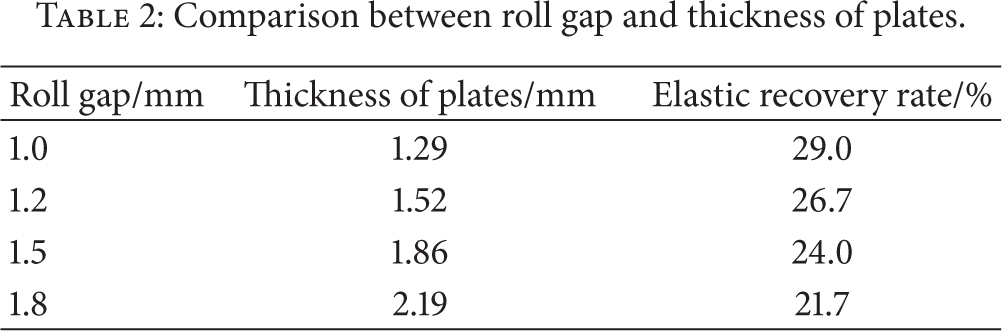
In CIDR process experiment, the temperatures of out-rolling and rolling force were measured, and the difference is little compared with simulation results. As can be seen from Figure 16, the PMMA plate temperature at the outlet of rolling gap is about 90°C, which is in accordance with the simulation results. The thickness of the obtained plates is bigger than the height of roll gap due to the effect of elastic recovery. The comparisons of the measured roller gap height and the measured plate thickness are shown in Table 2.
Comparison between roll gap and thickness of plates.
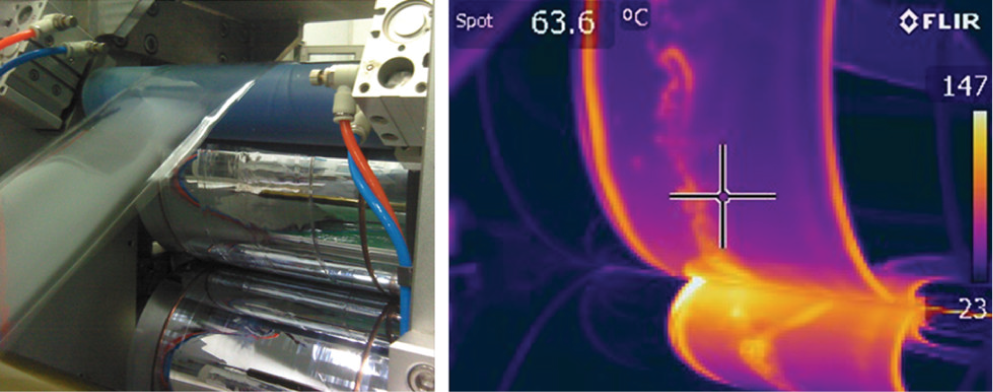
PMMA plate temperature test at outlet of rolling gap with thermal infrared imager.
The PMMA plate produced by CIDR experiments is shown in Figure 17. There is no depression, silver, corrugation, and microcracks on the surface of the plates; besides, flaws, impurities, and bubbles are not found in the material. Through testing the thickness of the PMMA plates, the longitudinal thickness difference is 0.005 mm/200 mm, and the horizontal thickness difference is 0.02/200 mm.

PMMA plate produced by CIDR experiment.
Figure 18 is PMMA sample's transmittance under light with different wavelength tested by spectrophotometer. From the figure it can be seen that different visible light can pass through the sample, and thus there is no dispersion phenomenon. Comparisons of transmittance, haze, and surface roughness of the sample with PMMA optical glasses are shown in Table 3. As can be seen from the table transmittance of the sample is 86.3%, and the haze of the sample is 0.61%; both of them are a bit worse than optical glasses because the roughness of the sample is bigger.
Comparisons of transmittance, haze, and surface roughness of the sample with PMMA optical glasses.


PMMA sample's transmittance for different wavelength.
Another important parameter to evaluate the optical performance of plate is birefringence, which refers to the phenomenon that light is decomposed into two perpendicular light waves when it passes through the anisotropic medium. The result of the birefringence of PMMA plate is shown in Figure 19. In Figure 19, the abscissa of the graph represents the transverse of plate (perpendicular to the flow direction of the material), whose origin is at one side of the plate, and different point every 10 mm from the side edge is selected to test. The vertical coordinate is the birefringence value tested in these different points. As can be seen from Figure 19, the birefringence of the sample is small near both sides and it is the largest in the middle. But all the values of birefringence are small compared with other methods [14]. According to the light elastic theory, birefringence is related to residual stress in the optical material [15], so the residual stress in the sample is small.

Birefringence testing result for PMMA plate.
6. Conclusions
A new forming method named CIDR process is presented to produce PMMA optical plate in this paper. The mathematical models of the temperature distribution, velocity change, and rolling force during the PMMA plate forming process are established. A new hot runner structure is designed in injection-rolling nozzle, which is demonstrated by stimulation that can ensure the uniform velocity of the melting material injected into injection-rolling cavity. Simulation analysis of the temperature distribution, velocity change, and rolling force during the PMMA plate forming process is carried out, and the results indicate that it is feasible and has positive instructive significance for experimental design.
Through the CIDR experiments of the sample machine, PMMA optical plates are obtained. The qualities of the PMMA optical plates are good by analyzing such optical performances as transmittance, haze, birefringence, and so forth. The CIDR process shortens the length of the production line, reduces the production cost, and improves the production efficiency. PMMA optical plate with high quality is the base of forming microstructure optical device with high quality. The research work of this paper has laid a solid foundation for the next work about CIDR process of the optical plates with microstructure patterns which will be reported in the next paper.
Conflict of Interests
The authors declare that they do not have any financial or associative interest that represents a conflict of interests in connection with the work.
Footnotes
Acknowledgments
This work was financially supported by the Corporation Project of Innovation Circle between Shenzhen & Hong Kong (no. JSE201007190020A) and the Fund of Key Laboratory of Advanced Manufacturing Technology for Mold & Die (no. MKL201302). The authors would also like to thank Professor ZhiHui Zhang from Hong Kong Polytechnic University for his kind help.