
Abstract
By analyzing characteristics of the DTC (direct torque control) system in electrical driving system, a shortcoming of the classical DTC method is to point out that it is unable to decouple the mutual interference between torque and speed, so that when a running asynchronous motor subjected to an instantaneous impact load, rotor speed and its deviation appears excessive fluctuations that can not be quickly restored to the initial set value. In this research, under conditions that without sensors for measuring load torque and rotor speed, to an electrical drive systems contains DTC devices, a novel ASCC (active speed compensation control) method is proposed based on ADRC (active disturbance rejection control) theory, on account of DTC model of asynchronous motor, a multiobjective observer is designed to regulate both the speed and the torque, and a proof of asymptotic stability that related this new control systems with the observer is made by theoretical deduction. Finally stimulating results show that this method can overcome the shortcomings of classical DTC system and greatly enhance the ability of the high-speed driving system to deal with unexpected impact loads.
1. Introduction
In the electrical control fields, the application rate of AC variable frequency drives in industrial electric control system accounted for more than 90%. Particularly, the VC (vector control) system and DTC (direct torque control) system based on accurate mathematical models have been widely used in industrial automatic control system that requires high precision and large range regulation of speed. By the approaches of certain models, extreme precision of static and dynamic system performance can be acquired. In the near two decades, SVPWM (space vector pulse width modulation) DTC system, which is proposed by the Japanese scholar Professors Takahashi and Noguchi [1] and the German scholar Professor Depenbrock [2] has become one of the mainstream methods. It is used for control system of AC asynchronous motor with performance of high precision. Recently, many scholars focus on the theory and application of the DTC system, compensation control of a DC motor, or improvement research in global scale [3]. And many papers are published, in which only the number of Chinese journals is more than 1600. On the other hand, for catering to the demand of high-speed actuation with commands of external load torque, some effective methods of torque measurement are adopted for the senseless driving system [4, 5]. Meanwhile, After being widely surveyed and studied, in many industrial cases, within which high-speed switch mechanism and hybrid circuits are integrated, a novel compensatory approach is necessarily applied for acquiring fast dynamics [6, 7]. What is more, it is not difficult to find in a large number of literatures concerning the modern control theory, detection technology, observer design, and intelligent optimization for improvement of DTC principle [8–10]. But most of the improvements still did not see clear progress. Particularly, the conclusion of advantages and disadvantages is similar in DTC and the VC method. Scholars generally believe that the advantages in DTC system include that (1) stator flux is easy to be calculated, and control accuracy is not affected by the variation of rotor parameters; (2) the on-off two position regulator within space vector Bang-Bang control makes instantaneous dynamic responses of motor torque that without dynamic transformation of coordinates come true; (3) although its main disadvantage is that when the torque has mutation, the response of the system has pulse signal. The mathematical model adopted and the static coordinate transformation in DTC are relatively simple, which makes the whole control system high-speed operation [11].
For torque ripple problem, this research has a clear analysis. It is recognized that the torque ripple is severely limited to the advantages of the DTC system. In other words, because of it is a space vector Bang-Bang switch control, in the actual system, due to the changing rate of current has limitation effect on the electronic devices; ideal states of torque response cannot be achieved. And a large change of load torque via the restrictions will induce fluctuations of speed. Due to these fluctuations, the speed regulator will not be able to quickly recover by approach of parameter setting, which is an inherent defect of principle and structure in the SVPWM DTC system. Therefore, in the situations that no impact load torque of the motor in DTC system, such as water pump, fan loads, and so forth. But in other cases, such as a load of rolling mill, when a steel product is bitten or cast, frequent impact disturbance will be caused. For catering to high precision requirements for speed matching, it is necessary to do an innovation in traditional DTC system, so that the new DTC system adapted to such occasion and even a wide field of application. This paper is aimed at the typical problem of electric control above. It is proposed for the first time, based on active disturbance rejection control [12, 13], designing an ESO (extended state observer) of impact load for DTC system. In the case that both without speed sensor and absence of direct load sensor, apply active compensation to the speed controller of the DTC system. With this algorithm, performance of the classical DTC system is improved significantly and the applicability is widened especially for impact load disturbance. What is more, for the new controller, the small gain theory is introduced to prove the stability of the whole control system. Finally, by the simulation experiment, this method is applied to the DTC system that the control task of high precision in both torque and speed responses is achieved.
2. Characteristic of Speed Response in DTC System
The block diagram of DTC system based on control principle in vector space is shown in Figure 1 [14].
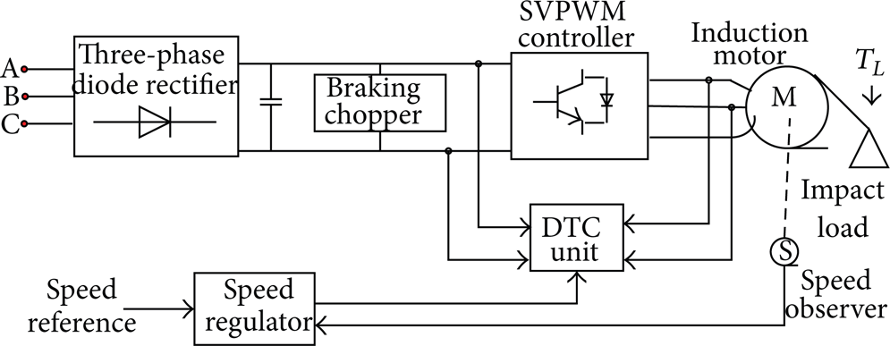
Structure of DTC system.
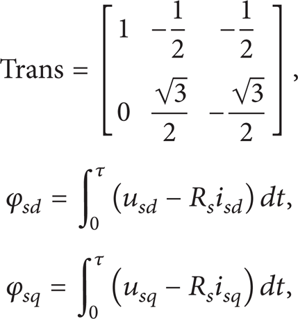
It is clearly seen in the figure that direct load torque on the motor shaft is perpendicular to axial direction. When no force sensor connects with load, the signal from impact load can be only acquired by the observers of electromagnetic torque in the motor stator. Its process is: when a sudden load impact on motor shaft, electromagnetic torque did not immediately changed, so rotor speed will fall, and the speed fall induce relative increment of Δω. Then through the nonlinear PI (proportional integral) speed regulator in ADRC unit, the quantitative convergence of electromagnetic torque response is improved significantly. Meanwhile, with the hysteresis effect of current Bang-Bang switch control, electromagnetic torque output is gradually accumulated till new balance achieved, as formula (1); ω is asymptotically stable:

where n
p
is number of poles in motor. i
sq
, i
sd
are two phase stator currents after the 3/2 transformation. ϕ
sd
, ϕ
sq
are two phase flux linkages after the 3/2 transformation. Then we get
Speed regulator in traditional DTC system is hard to overcome large parameters' changes induced from the impact load as well as speed overshoot in the AC motor. Contradiction may always exist that when coefficients of the proportion and integral regulator are too large to restore the speed overshoot in a certain period of time. This for the high precision of speed matching applications is not allowed. On the other hand, when coefficient integral regulator is small, the period of speed recover is not short enough, or overshoot may not be eliminated. For the occasion of high matching precision, the common regulator also can not be adopted. And no matter how to set the parameters of speed regulator, the speed error can not fully be compensated. The key reason is that the current loop in Bang-Bang control method has integral natural according to principle of formula (1).
In authors' opinion, now that the speed fall is unavoidable completely, the essence of the DTC system is space vector sector selection of inner current loop, which is actually a proportional switch of open loop system. So the open loop can only break the whole switch course down to several multistep sampling controls; even speed regulator is kept in state of saturated output, for the purpose of finishing the adjustment of the electromagnetic torque eventually. Because the on-off current value is also a limited value, it is can be seen from formula (1), as an integral process the derivative value of speed, which completely depends on the on-off current also has limited amplitude. Thus we may safely come to the conclusion that there is no full recovery of the motor speed, when a large load disturbance impacts on DTC system. So a novel speed compensation control is considered to join design of the DTC system.
Figure 2 shows the results of the theoretical analysis; particularly, when the AC motor is under a low speed state, the load disturbance makes deduction of the rotor speed reach 5%, and the speed fall cannot recover within 0.3 seconds. For instance, speed control system of finishing mill which lays in hot continuous rolling plant in metallurgical industry requires dynamic speed fall is less than 3%, during the recovery time that is less than 0.3 seconds. Therefore, according to the requirements of the indicators, intelligent extended state observer was proposed and designed for dynamic torque compensation control system with high accuracy speed response. The detailed parameters of the DTC system are given in the last section of this paper.
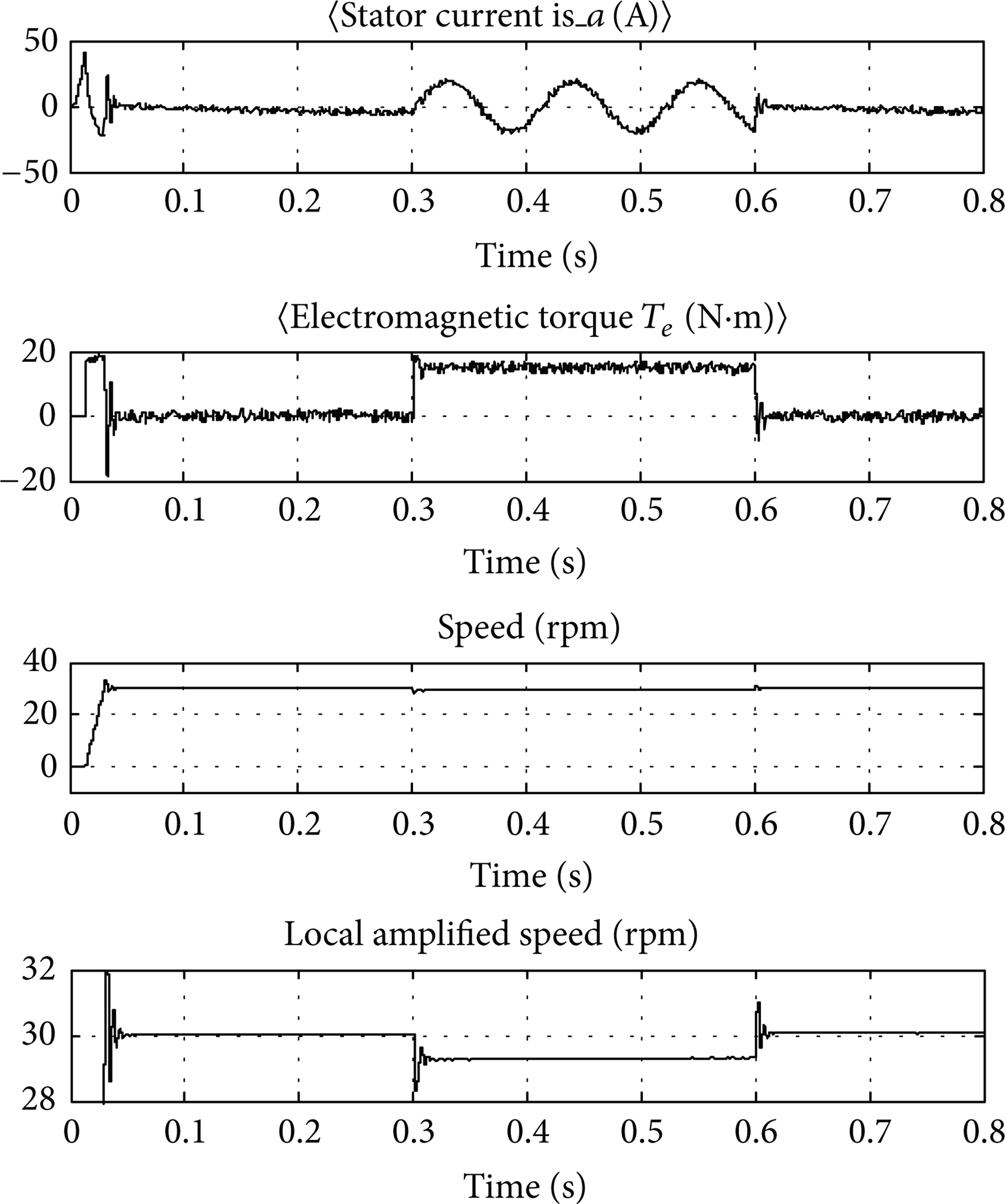
Speed and torque response of impact load disturbance.
It is obvious that impact load torques at the moments 0.3 to 0.6 seconds induce falling down of the rotor speed that cannot be recovered within short period.
3. Active Compensation Method of the DTC System
3.1. Principle of Extended State Observer [15]
Set second-order plant as

where ω(t) is unknown outside distance.

Real-time value of function f is

Concerning the nonlinear part, set a new variable x3(t) = f(x1, x2, ω); then the dimension of system is added one as shown below:

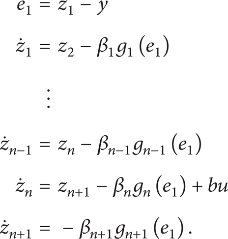
For the unknown time's function h(t) = f′(x1, x2, ω), in this system, which can be seen as similar linear system, an ESO is built as
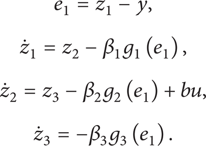
Aim of design of ESO is tracking the real-time values of the state variables observed as well as their derivative values:

Error equation corresponding to the observer n is as follows:
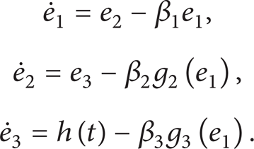
Although

The structure transformation of the exponential function can also be used in g i (e1). Because the exponential function has better linear characteristic near the origin, more accurate observation of small signal can be expected:

where k = (sign (e + δ) − sign (e − δ))/2. In function domain, the length of linear segment is 2δ that near the origin.
Contained in the electromagnetic torque load torque, acceleration/deceleration torque and, and the torque overcome mechanical loss (small, can be ignored). When there is no acceleration/deceleration torque impact on the motor, the speed differential becomes near to zero. Hence, electromagnetic torque is equal to load torque. According to this characteristic load disturbance observer can be designed, because system is in steady state while the impact load disturbance is suddenly added. The design of an intelligent ESO will be discussed in next section.
3.2. Design of Speed Compensation Controller
From the analysis above, in the case of no load detection sensor, load torque T L only can be indirectly obtained by intelligent observer of electromagnetic torque of the motor [16]. Based on ADRC theory, the observer can track not only the load torque, but also any order derivative signal of the electromagnetic torque. Similarly, in the premise of no speed transducer, with the designed ESO for rotor speed, the speed of the motor rotor can be gotten simply [17]; acceleration of the speed can be obtained also, though under the situation that without exact high order speed model. The basic relationship is still formula (1).
3.3. The Rotor Speed and Flux Estimation
The system state space variable is

The system input variable is

And the full order asynchronous motor state equation is
In this research, stable operation is focus point, and the rotor resistance of asynchronous can be omitted, so ψ
rq
= u
rq
= 0,

and output equation is
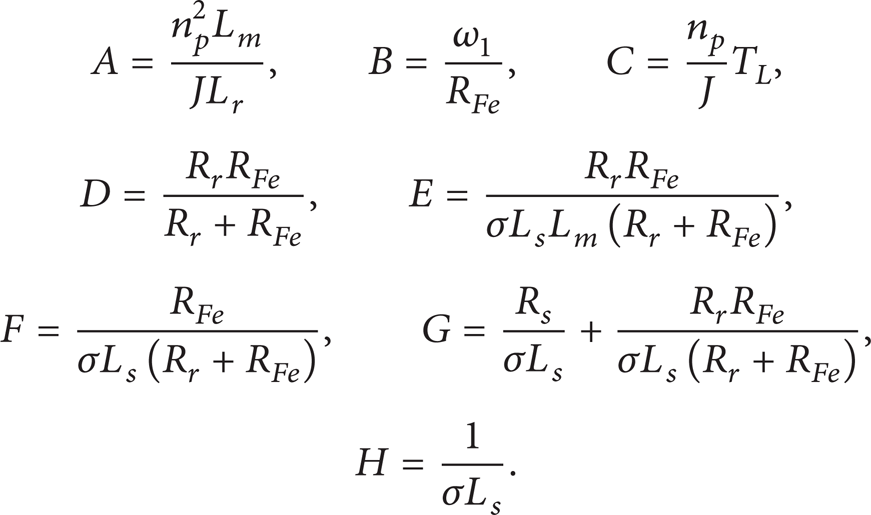
Including loss factors, the fourth order asynchronous motor state equation is

where
The system output function is

In formula (15), ψ, R, i, u, L, M represent the flux linkage, resistance, current, voltage, input inductance, and mutual inductance, respectively. The characters “d” and “q” note two phase rotating coordinates as d-axis and q-axis. “d” and “r,” respectively, express stator and rotor. R Fe is resistance of the rotor iron core. Respectively, J, n p , ω, ω1, T L are the inertia of the motor, the number of poles, the angular velocity of the mechanical rotor, the rotating angular velocity of d-q coordinate system, and the coefficient of output mechanical torque.
Magnetic flux leakage is σ = 1 − (L m 2/L s L r ).
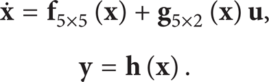
Note the affine nonlinear system model as

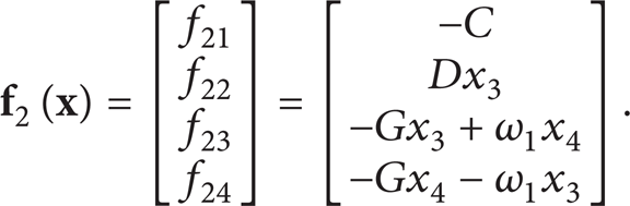
where

When the motor is running, some suddenly added or reduced torque will induce fluctuations of rotor speed. So the actual value of the speed is noted as

The other part is certainty that can be calculated:
Afterwards, concerning the uncertain part, constitute ESO of the rotor speed and flux:

With this observer the speed and flux can be estimated as well as the accelerations. And then extend this approach to the certain part of the system as shown in formula (21), substitute in i sd = f13 + f23 and i sq = f14 + f24, and estimated values of current will be obtained. Actually, in this process, unknown part including unmodeled differential variations of the rotor speed and flux, which have bounded norm. However, it should be attended that rotor flux model contains pure integral segment in open control loop, so in order to achieve the task that makes the whole main system steady with some small gain of the output from inner nonlinear PID regulator, the model of the observer has to be transformed and extended to

where

It is visible that via the modification of observer to join incremental part, the negative effect of the pure integral segment in flux model is significantly weakened. The operant
3.4. Stability of the State Observer
In some research, stability of linear observer has been discussed [18]. But to n-order affine nonlinear system, the research is meaningful.
Proposition: For any n-order system:

As long as the function f(t) is smooth. And the output value of the system
Proof. According to the principle of ESO, establish observer of the n-order system in proposition. Define the error between values of observer outputs and observed references of the state variable inputs as follows:
Take the error variable e equal to (z − x). We have
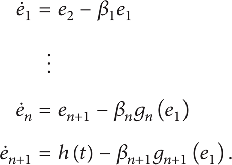
To state variables e, solving the differential equations, we get

when β
n
, βn + 1 > 0 and β
n
2 − 4βn + 1 > 0, t → ∞. The system enters the steady state that
Discussion. ∀p, 1 ≤ p ≤ n, according to the definition of observer error, have:
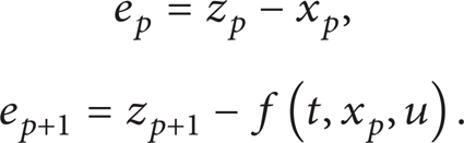
Because

Coefficient k is a constant. Then to
And because

substitute the feedback control law into formula

The corresponding characteristic polynomial is (s + k)(s2 + sβ
p
+ βp + 1). For the case k > 0, if

Then in the bicompact set
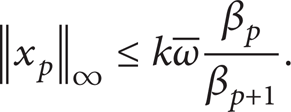
In summary, to all the
3.5. Design of Observer and Compensator
First of all, through the comparison of given speed and feedback speed, when the difference is smaller than a certain threshold, it is recognized with no acceleration/deceleration. So the electromagnetic torque equals the load torque observed in real time. Because the electromagnetic moment fluctuation is an inherent property of DTC system, the variance of volatility is easy to be estimated in the system and even sometimes can be measured directly. The variance rate of torque fluctuation is generally less than 20%. For a small load disturbances will not cause excessive decreasing speed, big impact load, which is usually more than 30% have to be considered to manage. For this purpose, choosing suitable torque threshold is important for acquiring accurate knowledge, by which we calculate the absolute value of error higher or lower than the limitation; the regulator provides a moderate compensation. This idea is derived from ADRC; applying this ESO to improve the precision of DTC system is very effective. Otherwise, it is difficult to realize the derivative signals in actual control engineering. The theoretical model of the load observer is shown in Figure 3.

Intelligent load observer model.
Actually, the moment information of observation contains the load torque, speed, and acceleration of torque that must be distinguished by intelligent choice based on the ESO and an additional filter. Because inherent existence of torque fluctuation and signals of speed and torque have nonlinear dependence relation, once compensation to the fluctuation is indiscriminate or unlimited, instable system with chaos outputs will be caused. Even self-excited oscillations or greater and speed fluctuation will be induced. Therefore, in addition to the choice of ESO, an appropriate filtering processing still needs to track feedback signals of electromagnetic torque and speed, to eliminate the high frequency noise in the fluctuations. Thought of the design is under the load torque disturbance, immediately to make quantitative compensation to the speed loop. However, the compensation quantity is decided by the size of the real-time load disturbance from observers. The gain of proportion coefficient k ps can be obtained through the actual measurement, generally values in the range of 0.05 to 0.09 (Figure 10):

The electromagnetic torque observation model is shown as follows:
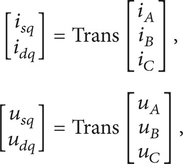
where the transfer matrix is
where R s is the stator resistance of AC motor. Because there are fluctuations in variable ω r , the output of the electromagnetic torque fluctuates in the normal steady state. The direct signal from observer should be put in a filter that high frequency noise is eliminated, before joining main speed controller. Set the time constant of velocity filter to 5~10 ms and the time constant of torque filter to 1~2 ms:

It is noted that this control system is implemented by digital modules. The continuous transfer functions can be converted into discrete transfer functions, using the bilinear transformation model. Similarly, in the flux observer design, integral module also needs to connect to such converter. This method is helpful to reduce the pure error of the integrator. Double transformation formula is

Filter models of bilinear transformation are gotten by substituting formula (38) into (39):

where K T = 1/T T , K N = 1/T N .
After filtering calculation selection model of speed controller as shown in formula (35) is brought in and then the compensatory output of speed controller via the feedback adder is induced to speed regulator to work together in DTC system.
4. Simulation Tests and Analyses
System simulation is developed in Matlab V7.8 (or more recent version). The simulation uses the discrete data system, in which sampling period is set as T s = 1 μs.
For test availability of the ASCC approach, a simulation test is made on virtual physical entities. This simulation is under the stator reference frame. The physical and simulation parameters for the DTC system are specified in Table 1.
Simulation parameters for DTC system.

The parameters of electronic devices in speed controller are specified in Table 2.
Simulation parameters for speed controller.

With the application of both ESO as formula (6) and filter as formula (40), the smooth outputs of rotor speed and acceleration are obtained. Similarly, the outputs about torque are easily gotten too. As shown in Figure 4, the output signals of z1, z2, z3 about torque and speed are displayed, respectively.

Output signals of ESO.
The experimental structure model of the general system is designed according to the principle shown in Figure 1. The entire model is composed of four subsystems, respectively, AC asynchronous motor model, PWM inverter module, DTC detection/control module, and nonlinear speed regulator module.
DTC system is referring to Japanese scholar Professor Takahashi's stator flux principle. As it is shown in Figure 5, stator flux trajectory is near a round circle; axis X-Y presents the flux or current in orthometric direction d-q.

Round locus of the stator flux.
When adding external load torque disturbance as random noise that amplitude is limited in ±5 (N·m). The speed outputs of DTC system without compensator fluctuating with the sum of inputs and noise wave. As shown in Figure 6, while to applied the ASCC technology, the output speed can be kept in steady state that has little ripples.

Comparation of speed outputs with ASCC or not.
More experiment results of the AC motor are shown in Figure 7. The response of rotor speed demonstrates that after joining ESO and speed compensation controller speed fall fully recover in a short period that less than 0.1 s, in local amplification curve (Figure 7(d)) can be much more clearly seen.
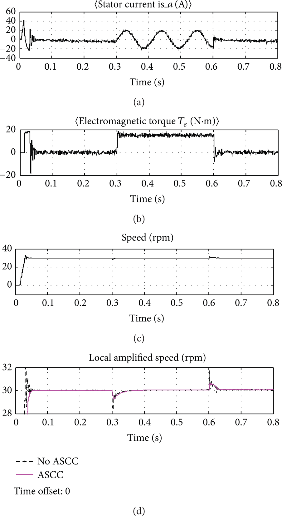
Outputs signals of DTC system with ASCC.
What is more, it can be found in this figure that the observer can effectively distinguish impact load torque and the common noise. Respectively, Figures 7(a) and 7(b) display the real-time stator current and electromagnetic torque that conforms to characteristic of asynchronous motor. It is clearly seen in Figure 7(c) that rotor speed is smooth under the effect of active speed compensation control. By joining speed compensation control segment, the expected goal of design at the beginning of this paper has been completely realized. In Figure 7(d), it is significantly shown that error of rotor torque is controlled less than ±0.5 rpm. The rate of the error is less than 2% that content to engineering demand completely. And the control effect can be obtained more clearly by comparison of Figure 7 to Figure 2.
For testing ASCC's effect on impact load and deeply displaying the characteristics of this new approach, more tests made under different conditions are given below (Figure 9).
Figure 8 shows with different input commands of the rotor speed range from 20 to 100 rpm; the real outputs can always be stabilized swiftly by the ASCC approach, though.
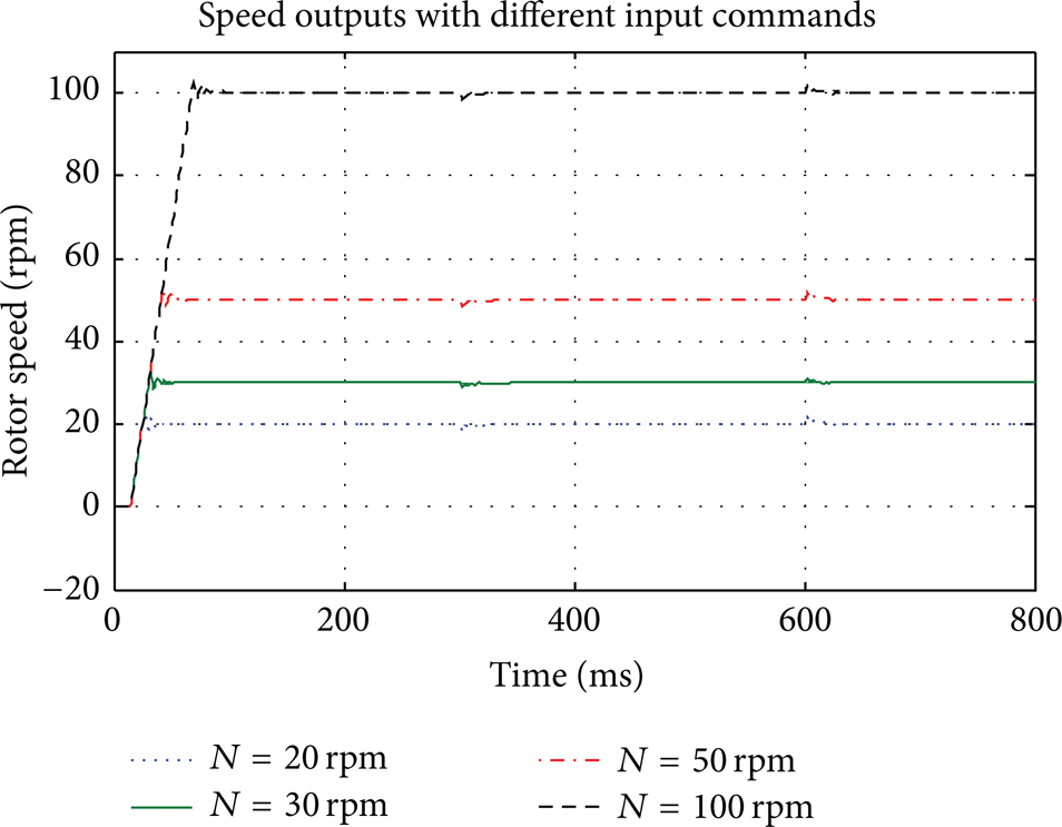
Speed outputs versus time with different input commands.
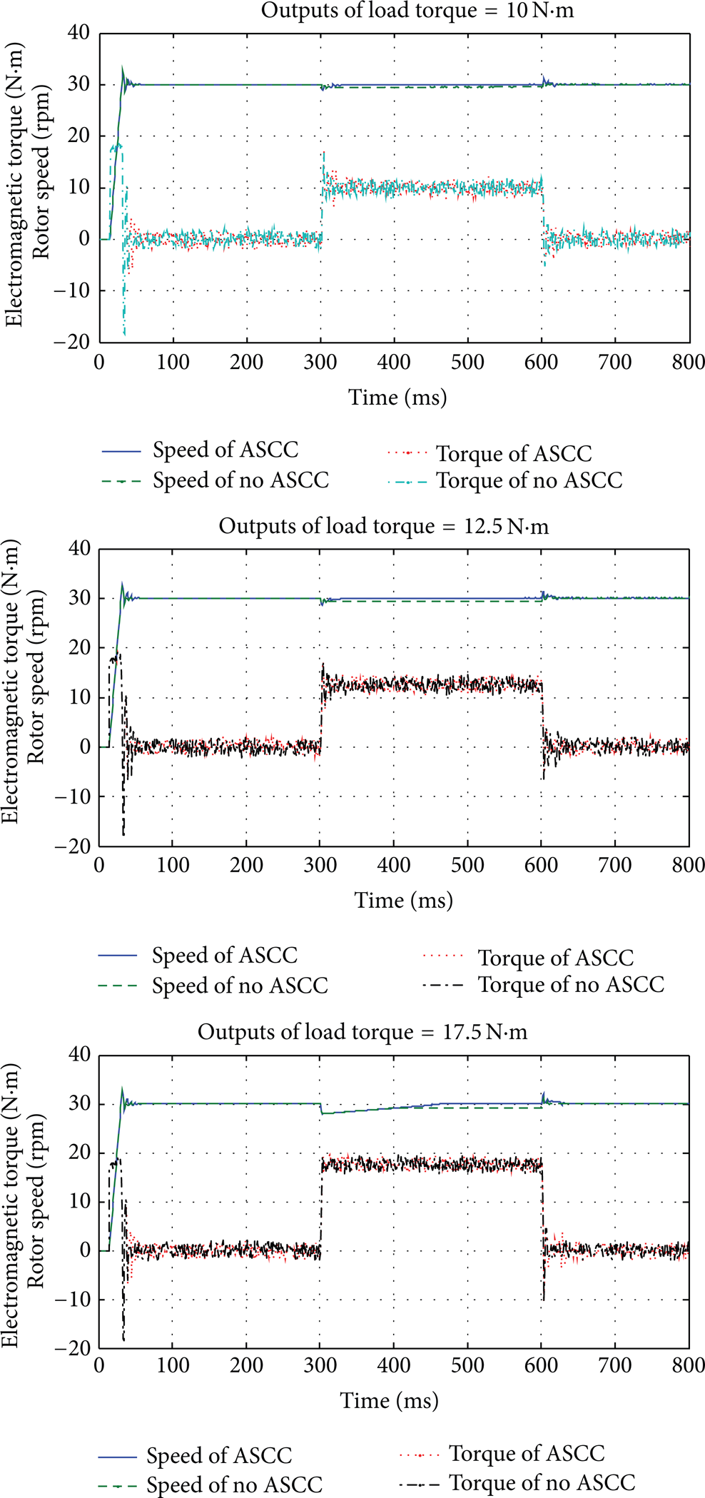
Electromagnetic torque and rotor speed with ASCC or not.

Speed outputs with different complement coefficients.
Similar to Figures 2 and 7, applied different impact torques range from ±10 to ±17.5 (N·m), the outputs of electromagnetic torque and speed at the rotor, under the situations whether compensation is added or not, are listed below.
From the comparison of three cases, it is verified that error of rotor torque can be constrained in a small range around the settled value. The rate of speed error is controlled less than 2%, and the recovery period is much short close to effect of real-time regulation. Within the scope of load capacity of the motor, control effect can be always in coincidence with expected performance.
Finally, to test capacity of the compensator, in the new DTC system, different values of the complementary coefficient kps that the key parameter in model as expressed in formula (35) are simulated.
The results show that the complement coefficient should be neither set too big nor set too small. Otherwise the cases of excessive or under compensation will be generated. So the parameter k ps has to be settled carefully reference the motor ability and actual working condition.
5. Conclusion
In order to make the DTC system applied in industrial electric drive device to impact load disturbance, this paper adopted a method called active speed compensation control. Under the condition of no load torque sensor, based on ADRC theory, design the motor load observer. For the purpose of guaranteeing response to impact load torque, at the same time, the compensation control of motor speed should be effective. After theoretical analysis and experiment, this idea has been successfully applied to several strip production lines (with large capacity AC asynchronous motor) in engineering practice. This study extends the application range of the DTC device and further overcomes the inherent phenomenon fluctuating speed as a result of an outside impact torque. The dynamic and static control precision and rapidity of the motor greatly improved. Can the overall performance of DTC system with such drive apparatus effectively be improved too.
Conflict of Interests
After confirmation with all authors they declare that they have no personal and financial relationships with other people or organizations that can inappropriately influence their research work. There is no question about the validity of their research with professional judgment and no professional or other personal interest of any nature or kind in any product, service, and/or company that could be interpreted as influencing the position presented in, or the review of, this paper.
Footnotes
Acknowledgments
This research is supported by National Natural Science Foundation of China (51205018), Research Project of State Key Laboratory of Mechanical System and Vibration (MSV201409), and Fundamental Research Funds for the Central Universities (FRF-TP-14-121A2).