
Abstract
Stick-slip vibration presents one of the main problems in the quality of drilling performance limiting tool life and productivity. This type of vibration can be suppressed by means of many approaches, such as varying parameters and use of control tools. Although tremendous improvements have been made in overcoming this dysfunction, stick-slip vibration suppression remains a large problem in the drilling industry. This paper provides an up-to-date review of stick-slip vibration behavior in drillstrings. First, the phenomena and the modeling methods of stick-slip vibrations are reviewed. Then an overview of the approaches for stick-slip suppression in oilwell drillstrings is presented, grouping the references under the categories of passive vibration control and active vibration control. Literature related to passive control is grouped under the categories of optimization of bottom hole assembly (BHA) configurations, bit selection and bit redesign, and use of downhole tools. The contributions related to the active control approaches for stick-slip mitigation are grouped under the categories of drilling parameters optimization based on real-time measurement and use of active control systems. Finally, related discussions and recommendations are conducted.
1. Introduction
Stick-slip motion is caused by the transition between static and kinetic frictions and is thus a dynamically unstable vibration [1]. Stick-slip vibration is common in a host of engineering systems, such as manufacturing systems [2], earthquake triggerings [3], brake systems [4], and vehicle systems [5]. Stick-slip is also common in the drilling of oil and gas, in which it is typically undesirable. Due to the fact that downhole vibration can dramatically decrease the rate of penetration (ROP) in drilling operations, stick-slip can significantly increase drilling cost. Stick-slip vibration in drillstring also increases tool failures, adversely affects borehole quality, and can lead to the coupling of different vibrations. In addition, with the development of the petroleum industry, the field is currently moving toward deep drilling systems. Due to high rock strength and poor formation drillability, stick-slip vibration is likely to occur in deep wells. Therefore, understanding its causes and predicting its formation and knowing how to suppress it are of significant importance in the drilling industry.
It has been well appreciated for many years that self-excitation at the bottom produces friction induced vibration, and this has led to the notion that stick-slip vibration is one of the primary causes of tool failures and poor drilling efficiency in the drilling process. The investigation of stick-slip vibration of drillstring can be traced back to the work of Belokobyl'skii and Prokopov in 1982 [6]. Today, an increasing number of researchers have put efforts in the investigation of this dysfunction to understand its root cause and determine efficient control schemes. Due to its significant influences on drilling operations, a workshop sponsored by the International Association of Drilling Contractors (IADC) regarding stick-slip mitigation was held in 2010, to increase the technology adoption rate of high-need applications in the petroleum industry [7].
Indeed, there are hundreds of references on this topic, and great effort has been made to study the properties of stick-slip vibration. Although a number of improvements have been achieved in investigating this dysfunction, progress has been much slower than expected, and many challenges remain. Presently there are a number of different approaches, whereby stick-slip vibrations are mitigated, and in this section these methods are summarized briefly before being elaborated in more detail in the main body of this paper.
Numerous methods for controlling the stick-slip vibration of drillstring, aimed at overcoming this damage, have been proposed by many researchers. It is not possible to say that one approach is superior to the others, as they all have benefits for some drilling conditions. In this paper, approaches for stick-slip vibration suppression are focused on, and the developments in the state-of-the-art in the field are reviewed. First, the theoretical basis of stick-slip vibration is briefly reviewed and then the approaches for stick-slip vibration control are reviewed by grouping the references under different categories.
2. Theoretical Background
2.1. Phenomenon of Stick-Slip Vibrations
Oilwell drilling is often accompanied by stick-slip vibrations, which are believed to be self-excited. Large cyclic stresses induced by stick-slip vibrations may lead to fatigue problems [8]. In addition, the high bit speed in the slip phase may excite other vibrations in the bottom hole assembly (BHA), which is not being anticipated to happen. Figures 1–4 show the responses obtained from theoretical models or field tests [8, 9]. Speed curves during stick-slip are shown in Figures 1 and 2, respectively, corresponding to [9, 12]. Torque variation and lateral displacement during stick-slip are, respectively, shown in Figures 3 and 4. As can be seen from the figures, the BHA periodically reaches a complete standstill during stick-slip. Torque builds up on the bit and is then released, leading to a rotational motion. The bit may be at rest for a while when it has been plugged into the formation and then it is released once the energy accumulated in the drillstring overcomes the threshold to break free from this situation. The bit alternately rotates faster and slower than the table, and the rotational speed and torque on the bit may be several times the values at the surface [12].

Stick-slip vibrations as seen in the bit and table speeds [8].

Downhole measurement of rotatinal speed during stick-slip [9].

Stick-slip vibrations as seen in the bit and top torques [8].

Stick-slip vibrations as seen in lateral motion [8].
In a study by Challamel et al. [13], the drillstring is considered as a beam in torsion. The drilling system can be described as follows:

in which the boundary conditions can be expressed as
where θ(x,t) is the angle of rotation, I is the inertia, I B is the inertia of the bottom hole assembly, β is the damping, G is the shear modulus, and J is the geometrical moment of inertia. The table speed (x = 0) is fixed at a constant value Ω, and the bit (x = L) is subjected to a torque φ, which depends on the bit speed.
Stick-slip is a typical nonlinear phenomenon, which is encountered in different mechanical problems. Stick-slip is related to elastic mechanics and dynamics tribology. It is of great difficulty to quantify the rock/bit interaction in some instability situations. Stick-slip vibration, however, plays a significant role in the drilling process. As a result, much work must be done in this field.
2.2. Modeling Methods of Stick-Slip Vibrations
In previous studies, the stick-slip vibrations of drillstring are attributed to the friction effects at the bit, and these motions are regarded as self-excited vibrations [14, 15]. Due to the importance of the vibration characteristics, various studies have been performed to investigate the behavior of the stick-slip vibration in drillstrings. Kyllingstad and Halsey [16] studied the drillstring dynamics caused by stick-slip motion, using a mathematical stick-slip model including the friction effect. The drillstring is assumed to be a simple torsional pendulum, and the BHA is treated as a flywheel; thus the equation of motion for the bit can be given as follows:

where

where θ is the angle of rotation, J is the effective moment of inertia of the system, S is the torsional stiffness of the drill pipe, Ω is the rotary table speed, which is constant, τ is the frictional torque acting on the BHA, ρ is the density, L1 and L2 are the lengths of the drill pipe and drill collar, and I1 and I2 are the cross-sectional polar moments for the two sections.
Based on the above pendulum model, the effects of damping, rotary table inertia, and rotational speed on stick-slip vibration, combined with the field torque data, are discussed. However, in this study the drillstring is treated as a simple torsional pendulum with one degree of freedom (DOF), and the BHA is modeled as rigid. In addition, viscous friction is neglected for mathematical convenience.
Similarly, Lin and Wang [17] studied the stick-slip vibration of drillstring by examining the dry friction effect on the drillstring vibrations, using a torsional pendulum of one DOF with torsional stiffness K and moment of inertia I. The equation of motion of the drillstring can be expressed as follows:

where φ is the absolute angle of rotation,
Here we introduce the following symbols:
where ω0 and ζ are the natural frequency and viscous damping ratio of the system. The equation of motion can be represented by the following:

Then a continuous exponential form of dry friction is used and presented in the following:

where f1 and f2 are the maximum and minimum values of
Based on the model, numerical solutions and stick-slip cycles are obtained. In their study [17], the beating phenomenon is interpreted as the stick-slip vibration, and a phase plane of the BHA is given as an explanation for the stick-slip vibration. The effects of the rotational speed, viscous damping, and natural frequency of the drilling system on the stick-slip vibrations are also discussed.
Coupled torsional and bending vibrations of drillstring were investigated by Yigit and Christoforou [18], by combining simulation results with laboratory and field observations. It was shown from the study results that controlling the surface torque, rather than rotary table speed, could eliminate the stick-slip vibration. In [19], the drillstring dynamics were studied using a lumped parameter model, which considered the coupling between torsional and bending vibrations, as well as the interactions between the drillstring and the wellbore.
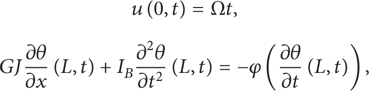
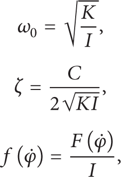
Richard et al. [10, 20] established a discrete model to study the self-excited stick-slip vibration of drillstring, considering the coupling between axial and torsional vibrations through bit rock interaction laws which include both the cutting process and frictional contact at the bit rock interface (Figure 5). In the model, H0 and Ω0 are the upward force and angular velocity applied by the rig on the drillstring, M and I are the point mass and moment of inertia of the BHA, and C is the torsional stiffness of the drill pipes. The equations of motion of the system can be written in the following forms:
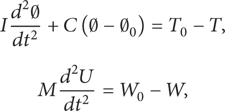
where

where ∅ and U are the angular position and vertical position of the bit, T and W are the torque and weight on bit (WOB), and T0 and W0 are constant quantities corresponding to the steady-state response of the bit.
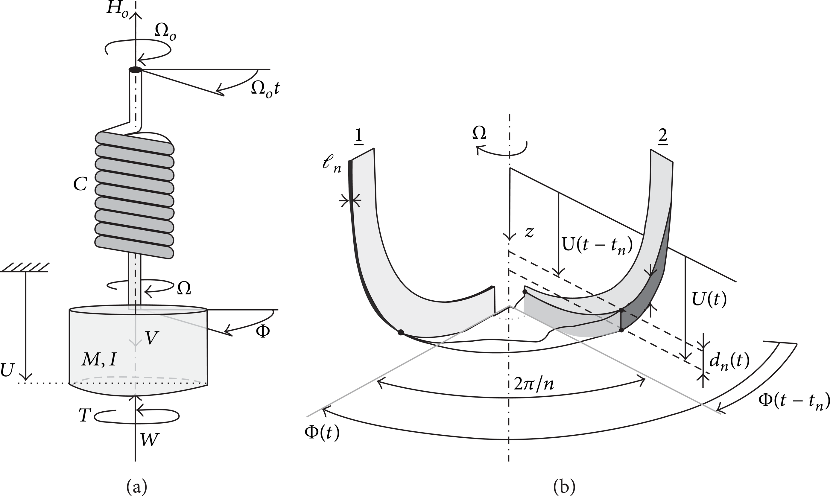
Mechanical model of the drilling system [10].
In the model presented in Figure 5, the drillstring is treated as a single lumped inertia in the axial direction. The WOB is assumed to be constant, which can be achieved by controlling the hook load, signifying that the axial movement of the drillstring at the surface must be controlled so that it is equal to the axial movement of the drill bit. The drill bit, however, vibrates frequently in the axial direction; thus in practice it is unrealistic to realize the condition proposed in the model. Based on this, Besselink et al. [21] included the finite axial stiffness of the drillstring and axial viscous damping to model the frictional dissipation along the BHA and then used a semianalytical approach to obtain the stick-slip limit cycle, using numerical optimization to determine the unknown parameters.
The models in [10, 20] only apply to the vertical borehole, and the lateral motions of the bit are not considered. Of course, it is not reasonably practical for a model to cover all relevant phenomena, due to the fact that the vibrations of the drillstring are present and sometimes coupled. Based on this model, Germay et al. [22] used a dimensionless formulation to describe the system and then used an approximate model of the decoupled axial dynamics to derive the solution of the axial equation and the analytical expression of the axial dynamics to derive expression of the velocity weakening friction law, which can be used to provide recommendations for reducing the amplitude of the torsional vibrations.
By deriving a mathematical model and solving it as an initial value problem, Baumgart [23] reported the influence of mud properties on the onset of stick-slip vibration. In the study, the principle of virtual work was used to derive the equations of motions for the pipe. The stresses between pipe and mud were treated as external loads on the pipe. Leine et al. [24] developed a stick-slip whirl model to explain the drillstring dynamics when both stick-slip and whirl vibrations were involved, using bifurcation theory to explain the occurrence of stick-slip vibration.
Navarro-Lopez and Cortes [25] performed the analysis of occurrence of stick-slip vibration at the BHA. In their paper, dynamical analytical tools were used to present the detection of the drilling parameters and operation recommendations in drillstring. The drilling system is considered as a lumped parameter model which considers the increases of the drillstring length during the drilling process. Gulyaev et al. [26] studied the self-excitation of stick-slip vibration of a rotating drillstring caused by the interaction between the bit and rock. Based on the d’Alembert principle, a wave torsional pendulum is constructed in the form of a nonlinear ordinary differential equation with delayed argument. The dynamics of the torsional vibrations can be expressed as follows:

where φ is the elastic torsional angle for the drillstring element, t is time, β is the propagation velocity of the torsional wave, and z is the axial coordinate from the bit.
The d’Alembert solution of the wave equation can be written as follows:

where f(z − βt) and g(z + βt) are the arbitrary continuous functions which define the waves propagating in the positive and negative directions along the axis of the drillstring. Then, computer simulation is used to determine some of the special features of stick-slip vibration of drillstring. The damping effects, however, are not considered in the mathematical model.
Barton et al. [27] investigated the dynamics and bifurcations of the drillstring model using a neutral delay differential equation. The authors believed that the existing routines based on polynomial approximations are incapable of dealing with the arbitrarily weakly damped modes. In their study, numerical continuation routines based on Fourier methods were developed to analyze the stick-slip model. Mihajlovi
Liu et al. [29] developed a discrete model of drillstring with eight degrees of freedom, considering both the stick-slip vibration and time delay effect. Numerical studies with different drilling operations showed the self-excited characteristics and the effect of driving speed on system stability. In a series of papers, Khulief et al. [30–33] developed and investigated a dynamic model for drillstring. Gyroscopic effect, coupling between torsional and bending vibrations, and the effect of the gravitational force field are all considered in the model. Liao et al. [34] developed reduced order models to study the stick-slip vibration of drillstring. Numerical studies and laboratory experimental investigations of a rotor have also been conducted to further understand this nonlinear motion.
2.3. Laboratory and Field Observations
Laboratory tests have been carried out extensively for the verification of the occurrence of stick-slip vibration and derived stick-slip response. Brett [35] conducted laboratory measurements to confirm the previous findings which showed that torsional vibrations can result from the bit characteristics. In [33], an experimental investigation of drillstring dynamics was presented, using a specially designed laboratory test rig. Melakhessou et al. [36] studied the local contact between the BHA and the well during drilling operation, using a mathematical model of four degrees of freedom, to simulate the local behavior of the drillstring at a contact section. In the investigation, a laboratory experimental apparatus with two optoelectronic devices was used to validate the model. Dykstra et al. [37] and Chen et al. [38] conducted a series of laboratory tests to study the stick-slip vibration of roller cone bit. Laboratory and field tests on an instrumented bit were carried out by Leseultre et al. [39] to examine its performances on producing direct measurements in both the time and frequency domains, and these measurement dynamics can be used to identify stick slip and whirl. Schmalhorst [40] conducted a laboratory experiment on a full-scale assembly comprised of a bit, a downhole mud motor, and a thruster, to quantify the bit dynamics. The results showed that introducing a thruster into the BHA aids in avoiding stick-slip vibration.
In [33], field drilling tests were also conducted in a well in southern Wyoming, to compare the theoretical model with the laboratory tests. Combining drilling expertise with an advanced dynamics model, Wu et al. [41] identified the root cause of stick-slip vibration in a wide range of drilling applications. Use of this model allows engineers to focus on suitable solutions rather than trial and error approaches. Stroud et al. [42] studied how the roller reamer may be used to replace a stabilizer, by means of laboratory and field tests results. The results from the tests showed that the use of rolling elements at borehole contact points is effective for reducing backward whirl and stick-slip vibration. In fact, many field observations regarding stick-slip vibration are studied in search of vibration control methods. More information related to field observations can be found in the following two sections.
3. Passive Stick-Slip Suppression
Vibration control of mechanical systems is highly desirable to control the unwanted motion of the system, which may eventually lead to the fatigue and failure of the devices. One of the most common and efficient approaches to achieve vibration control is the passive control scheme. Over the past several decades, this approach has been extensively adopted to control the dynamic behavior of drillstring. In this section, the passive control approaches used for the stick-slip vibration suppression are discussed. The literature is grouped under the categories optimization of BHA configurations, bit selection and bit redesign, and use of downhole tools.
3.1. BHA Configuration Optimization
BHA is an important part of the drillstring, and the BHA design plays a significant role in drillstring dynamics and drilling performance. As pointed out in the previous section, the stick-slip vibration in the BHA is an important cause of failure of drilling tools. Many investigators have attempted to solve this problem by optimizing the BHA configurations. With this idea in mind, detailed studies of the stick-slip vibration suppression have been made.
Due to the fact that all downhole tools may be responsible for the stick-slip vibration, Fear et al. [43] studied the BHA effects in a paper focusing on the effects of bit on drillstring dynamics. The stabilization effects were investigated by comparing two runs with the same type of bit; that is, one bit was run without a near bit stabilizer, while another bit of the same type was run on a near bit stabilizer BHA. The study revealed that the stick-slip is related to the bit freedom to move laterally, rather than only being due to the speed variation of the bit. They also revealed that placing the bit in forward synchronous rotation by the motor bend may also aid in mitigating stick-slip.
Janwadkar et al. [44] conducted a drillstring dynamics analysis, including buckling load, critical speed, and torque, and revealed that stick-slip and bit whirl result in reduced ROP and premature bit damage. The natural frequencies of the BHA are related to the applied weight, operating conditions, and physical characteristics of the BHA but not rotational speed. Some sources of the excitation include the drill bit, mud motors, and stabilizers, and resonance occurs when a frequency of the excitations is equal to the natural frequency. The authors analyzed the mode shape of the BHA at each of the critical speeds to redesign the BHA, and the results showed that the BHA redesign considering weight, buckling, and critical speed delivers exceptional drilling performance, that is, 42–121% improvement in penetration rate with minimal bit damage.
In order to mitigate the occurrence of stick-slip vibration, some engineers have decided to gradually increase the BHA stiffness to improve the transmission of the energy to the bit [45] and reduce the magnitude of stick-slip vibration [46]. During the drilling of horizontal wells, however, generating high torque has been shown to be a problem in practice, and increasing the BHA stiffness may aggravate the drilling situation. Jaggi et al. [47] studied the BHA effects on stick-slip vibration by combining a stiff-string modeling method using available field data. In the case studied, based on the integrated rotary closed loop system, one 5-inch heavy weight drill pipe on either side of the drilling jar is recommended to be replaced with a 6–3/4 inch drill collar.
Mahyari et al. [48] studied the effects of stabilizer placement on drillstring instability. However, the drillstring is assumed to be a balanced system, and the rotation of the drillstring and thus helical buckling are not considered. In addition, only static stability analysis is used, and stabilizers are assumed to be in contact with the wall. Jansen [49] studied whirl and stick-slip vibrations of drillstring in terms of rotor dynamics, with consideration to the stabilizer clearance and stabilizer friction. Results from the analysis may be helpful to the BHA design. The mechanical system, however, is simplified to be a model and includes a single span of drill collars supported by two stabilizers. It is too simple to provide a quantitative solution of drillstring dynamics, and a large number of degrees of freedom should be taken into account.
Minimizing bit-BHA interactions by BHA optimization is described as being a key factor to obtain superior ROP and stability in a study by Wu et al. [11]. The authors illustrated the concept of optimum zone to decouple stick-slip vibration and whirl, in combination with several case studies. For a given condition, the critical WOB and rotations per minute (RPM) triggering whirl and stick-slip can be predetermined. Plotting the critical values which represent the boundaries of stable drilling parameters in a coordinate, a closed domain defined by the boundaries is known as the optimum zone (Figure 6). The critical values represent the boundaries of different drilling conditions, such as the maximum torque limited by rig and minimum ROP specified by operators. Theoretically, the drilling parameters in the optimum zone guarantee the BHA stability. The bit and the mechanical properties of the rock to be drilled are the major factors affecting the optimum zone. It is demonstrated that obtaining a maximum ROP while keeping the BHA stable is realized by decoupling potential stick-slip and whirl.

Schematic description of optimum zone [11].
The drillstring dynamics, however, reduce the domain due to bit-BHA interactions. Under extreme conditions, the dynamics can lead to the crossing of the boundaries of stick-slip and whirl. Figure 7 shows the annihilation of the optimum zone due to the coupling of whirl and stick-slip. In this case, any attempt to control vibrations by adjusting the drilling parameters will most likely fail. When solving the coupling of stick-slip and whirl, BHA optimization can be used. In general, the optimum zone concept is useful for increasing the drilling efficiency if the drillstring dynamics can be quantified. The challenging aspect, however, is that it is difficult for this method to measure the magnitude of each vibration type accurately, especially when several of them are coupled.

Annihilation of optimum zone due to coupling of whirl and stick-slip [11].
Bailey and Remmert [50] studied the BHA redesign used for managing drilling vibration and improving penetration rate. The key design changes resulting in these improvements were identified by a dynamic model of the BHA and then a frequency domain dynamic model in predrill forecast and postdrill hindcast was used to evaluate the BHA design. Field investigations of the original BHA and redesigned BHA were studied, and the results revealed that the model used for evaluating the BHA is demonstrated to be effective in stick-slip suppression.
During the drilling of interbedded formation to access natural gas, stick-slip usually reaches an unacceptable level. An analysis methodology to determine the root cause of drillstring vibration is required for the operator to optimize the BHA and drilling parameters. Rahman et al. [51] used a finite element analysis-based modeling system to analyze the improvement scheme of drilling performance. The results of the simulations were used to explore the cause of drilling dysfunction, and various BHA configurations were run under different drilling conditions to study the BHA effects and BHA redesign. Considering the fact that the improvement of BHA depends on collecting dynamical downhole data and logging information along with operating parameters and bit dull conditions and that these parameters are different for different wells, thus there are many limitations to applying this method in practice.
3.2. Bit Selection and Bit Redesign
Laboratory and field tests of roller cone bits were performed to study the dynamics of the drill bit and drillstring [37]. In [38], Chen et al. investigated the vibrations a roller cone bit undergoes, and these vibrations were shown to affect bit performance in terms of ROP, insert breakage and bearing, or seal life. Field runs have proven that a force balanced bit drills smoother and has better durability than conventional bits and that bit imbalance forces are the main causes of bit vibration. However, the study did not show the factors which may influence the bit imbalance forces. In [52, 53], a roller cone bit with a balanced cutting structure was developed, for which energy balancing and/or force balancing are referred to, which has been proven by tests to be efficient in improving ROP and mitigating stick-slip vibrations. The life of this type of bit has not been mentioned in previous studies.
With the growing demand for utilization of polycrystalline diamond compact (PDC) bits in tough formations, significant challenges have been presented for the advancement of hard rock drilling performance. The major cause of reduced PDC bit life is attributed to downhole vibration induced by an imbalance of forces. On the other hand, greater energy is required to fail harder formations, which signifies a higher energy accumulation in the drillstring and a greater likelihood of vibration problems. Over the past several years, various bit design methods have been introduced to mitigate downhole vibration, including blade spiraling, force balancing, high back rake gauge cutters, impact arrestors, and use of asymmetrical blade layouts. Ortiz et al. [54] studied the effects of lateral and torsional vibrations on PDC bit performance, and the cause of torsional vibration creates an imbalance force which causes the bit to engage the borehole. The damping effects, however, were treated as harmonic forces.
Due to the fact that surface measurements do not monitor downhole dynamics precisely, downhole vibration is a problem which remains to be solved. A study by Leseultre and his collaborators presented an instrumented bit with accelerometers, strain gauges, and contact sensors [39]. These sensors are used to produce direct measurements in both the time and frequency domains, including bit rotational speed, bit acceleration, WOB, torque on bit, eccentricity of wellbore, ROP, bit wear, and specific energy. With the use of these measurements, stick-slip vibration is clearly identified. The data from this instrumented bit can be used to modify the bit design and BHA selection. This tool is developed to improve the data reliability of the present ones, because the measuring tool should be arranged as close as possible to the bit. The drill bit is a precise instrument. The tool life of the instrumented bit, however, may decrease considerably since such a large number of sensors or gauges are located in the bit. In addition, due to numerous factors, serious vibrations and high temperature, for example, practicability of this technique remains to be proven.
Managing the depth of cut to mitigate the torque fluctuations which can excite unwanted vibration is one key solution for reducing stick-slip vibrations. The cutter exposure is correlative to the occurrence of stick-slip vibration by affecting the blade surface contacts with the formation. The bit can be designed to be more or less aggressive by limiting the depth of cut in the cone profile area of the bit. A series of works have been conducted to study the depth of cut of the bit [46, 47, 55–57]. Davis et al. [46] regarded the depth of cut control as one of the two key solutions to reduce stick-slip vibration. Combining with field record data, the study revealed that the depth of cut control provides significant mitigation in vibrations, leading to improvement in ROP, downhole life, and borehole quality. A study by Jaggi et al. [47] showed that the depth of cut control reduces bit-induced torsional vibration, while increasing WOB and increasing drillstring dynamic stability. However, many of the design changes introduce more sliding or rubbing, which leads to a reduction of the drilling efficiency.
Richard et al. [55] presented a model which considered the coupling between torsional and axial vibrations. Rate-independent bit-rock interaction laws and laboratory results from single-cutter experiments were used to optimize the bit configuration. Schen et al. [56] studied the bit selection using a new vibration logging tool which acquires near-bit data. The key point of this method, however, is the logging tool rather than the drill bit. Pelfrene et al. [57] experimentally and theoretically studied the role of the bit in the stick-slip vibration to predict and prevent this dysfunction. What should be stressed is the fact that the bit used in the experiment is a single-cutter PDC bit.
Due to the cutting mechanism, the PDC bit is more likely to be affected by vibration forces which usually lead to stick-slip than roller-cone bit. Combining state-of-the-art cutter technology with advanced PDC bit design has led to much progress in bit application. Schell et al. [58] studied the PDC bit with abrasion-resistant cutters and competent stable characteristics are involved through trial and error. The bits, however, are developed only for the formations in eastern Texas and northern Louisiana.
Niznik et al. [59] investigated how the integration of BHA and bit mitigates stick-slip vibration. However, this method is relatively statistical and empirical, and as a result large amounts of drilling data are required. Barton et al. [60] believed that the stick-slip results from the rotational speed fluctuations and erratic torque are a major factor leading to drilling problems. The authors evaluated and optimized the basic characteristics of the drill bit designs to provide an effective solution. The four key factors derived from research of the cutting structure design are ROP index, durability index, lateral stability index, and side cutting index.
Fear et al. [43] presented the nature of bit failures, their dependence on drilling conditions, and practical suggestions for avoiding bit failures. It was shown that adding stabilization to the BHA delays but does not eliminate the stick-slip and that running a PDC bit on a steerable motor may remove the stick-slip vibration. Wu et al. [11] developed the optimum zone concept to solve the coupling between stick-slip and whirl. One of the two key factors is maximizing the optimum zone by optimizing bit structure. The challenging component, however, is to identify the stick-slip, since it often couples with the whirl.
Rahman et al. [51] investigated the bit selection in mitigating stick-slip vibration through case studies. A study by Pessier and Damschen [61] showed that the stick-slip vibration on the hybrid bits is as much as 50% lower than conventional PDC bits. The favorable dynamics of this type of bit, however, are not beneficial in small-diameter bits.
Jain et al. [62] believed that the models and methods that have been presented must be systematically tested and compared in a controlled environment. In their work, they demonstrated that PDC bit design has a significant effect on stick-slip vibrations. They reviewed five leading theories and put them to test by designing and manufacturing pairs of PDC bits, with each pair incorporating a bit with a standard design and a bit embodied one of the theories.
The effects of bit/rock interaction and formation properties in contact with any bit play an important role in the development of stick-slip and its behavior. In [12, 55], the bit-formation interaction role in stick-slip trends is investigated.
3.3. Drilling Input Parameters and Stick-Slip Behavior
Combinations of drilling input parameters also have a great impact on the stick-slip vibration. The combinations of rotary speed and WOB, or combination of input torque and WOB, have great impacts on the stick-slip occurrence and behavior. For example, Baker Hughes suggested that increasing RPM and reducing WOB help to mitigate stick-slip vibrations [63]. However, the price paid for this strategy is usually a substantial loss in ROP.
Yigit and Christoforou [18] investigated coupled torsional and bending vibrations of drillstring subject to impact with friction. The results showed that the combined parametric and forcing excitations significantly affect the stick-slip vibration. The results from another study by the same authors showed that the control action may excite large bending vibrations for some operational parameters, due to coupling with the stick-slip motion [19]. In [51], an optimum range of operating parameters with different WOB or RPM combinations were provided to the field to ensure the highest possible ROP. Patil and Teodoriu [64] analyzed the influence of drilling parameters such as surface RPM and WOB on stick-slip vibrations and revealed that the stick-slip of the bit is converted to torsional vibrations, and ROP is also increased with increasing surface RPMs. In addition, reducing the WOB eases stick-slip but reduces ROP.
3.4. Use of Downhole Tools
Schmalhorst [40] studied the use of a bit motor thruster in the BHA of a drillstring. Computer models of the dynamic system were developed and laboratory measurements of a full-scale equipment setup containing a bit, a motor, and a thruster were performed to predict the dynamic behavior of the drill sting. Case studies have also shown that the thruster is beneficial for drilling, because it improves the ROP and drilling by mitigating stick-slip vibration. Barton et al. [65] presented a drilling agitator tool which has demonstrated significant improvements in drilling performance, by mitigating stick-slip at the drillstring. Case studies have shown that these improvements resulted in an average of 30% longer runs and a 35% increase in ROP. The vibrations induced by these tools, however, have not been evaluated in the researches.
Ochoa et al. [66] presented the concept that setting a rotary steerable tool below a high-torque positive displacement motor provides the benefits of both conventional and rotary steerable system drilling. In addition, the increase in rotational speed reduces vibration perpetuation, and the motor mitigates the effects of stick-slip vibration. This method guarantees a constant trajectory control and provides the maximum possible energy to the bit, that is, mechanical and hydraulic. However, the system also requires additional hydraulic energy for optimal performance. Due to the instability of the rig in controlling the extra pressure drop, the flow rate is usually reduced, and this causes a detriment in the borehole cleaning.
The development of antistall technology aims to determine a way to prevent excess energy accumulation in the drillstring and act on the rock breaking process to lower the risk of stick-slip [67]. This technology has been proven to be efficient in reducing stick-slip vibrations and bit stalls.
Many researchers have studied the role of roller reamers in improving drilling performance. Sowers et al. [68] showed that the use of roller reamers reduces the occurrence and impact of stick-slip features. The authors presented a conceptual model for coupled stick-slip and whirl-induced borehole features and provided representative examples to show improvements in drilling performance using roller reamers. They revealed that replacing stabilizers with roller reamers is an effective approach to decoupling stick-slip and whirl. Zakuan et al. [69] believed that roller cutters of the roller reamer rotate around the wall and provide a low torque point of stabilization and that the roller reamer plays a role in introducing a low-friction bearing between the drillstring and borehole.
The roller reamer, however, increases friction factors which can result in drilling issues in extended reach wells, especially in the drilling of horizontal wells. In addition, it is worth noting that the life of roller reamers at operating conditions is not unlimited, and the tool life is highly dependent on the downhole drilling conditions.
Wedel et al. [70] studied the use of a torsional impact hammer in mitigating stick-slip vibration. High frequency torsional impacts are generated in the hammer; these rapid impacts effectively remove the reactive torque accumulated in the drillstring and decrease the threshold at which the stick-slip is broken. Deen et al. [71] tested a torsional impact hammer in applications and described how the torsional impact hammer has improved drilling performance and reduced drilling costs. The authors believed that the torsional impacts improve the efficiency of the traditional shearing rock failure mechanism. Axial excitation is another approach to mitigating stick-slip vibration.
Forster [72] investigated the introduction of axial excitation into stick-slip mitigation, combining small-scale rig experiment and full-scale field testing. However, it is known from practical applications that high-frequency impacts considerably decrease the tool life of PDC bits. Therefore, this is a source of serious limitation for bits in practice. Ghasemloonia et al. [73] studied the drillstring vibration in vibration assisted rotary drilling, using both a coupled nonlinear elastodynamic mathematical model and a dynamic finite element method model. In addition, Batako et al. [74, 75] investigated a self-excited percussive rotary drilling system which used the stick-slip properties to form impacts; the system was analytically researched via a phenomenological viscoelastoplastic model and was numerically studied to reveal the full response of the model in the vibroimpact approach.
4. Active Stick-Slip Suppression
As detailed in the previous section, passive solutions have been used to solve the downhole vibration problems, but the performance of many of these approaches is limited, due to the fact that the optimization process can be costly and time consuming. Some variations may result in performance deterioration rather than optimization, as with any trial and error operation. The vibrations, however, can be effectively controlled when real-time details are provided. In many drilling applications, active control by the use of downhole measuring tools and active control systems has been used to mitigate the vibration of drillstring. In this section, the studies related to the active control approaches for stick-slip mitigation are discussed and their contributions are grouped under the categories of drilling parameters optimization based on real-time measurement and use of active control systems.
4.1. Drilling Parameters Optimization Based on Real-Time Measurement
Dufeyte and Henneuse [76] characterized the stick-slip motion by analyzing simultaneous downhole and surface drilling data. The results showed that it is possible to reduce stick-slip by varying the drilling parameters such as WOB, rotational speed, and mud characteristics and thus control drill pipe fatigue and bit wear. This approach, however, must be based on several thousands of real-time field measurements. A study regarding vibration detection from a mud system performed by Fear and Abbassian [77] revealed that stick-slip vibration is common in hard drilling environments and is a primary cause of tool failures. The suppression of this type of vibration with an automated vibration motoring system, torque feedback, and rig-site vibration mitigation guidelines has led to significant improvements in drilling performance.
Physical models improved by comparing the results with the actual surface and downhole data must be used while drilling in optimizing the drilling process [78]. Pavone and Desplans presented the use of a measurement while drilling (MWD) system in obtaining the downhole drilling data. The authors explained why stick-slip disappears when the rotational speed is increased or WOB is decreased. However, the model assumes the stick-slip to be a steady-state motion.
Shuttleworth et al. [79] presented the suggestions arising from the study of a real-time downhole vibration monitoring, in combination with revised drilling operations, to reduce stick-slip vibration when encountering the interbedded formation. Robnett et al. [80] presented a method of determining the stick-slip vibration downhole from magnetometer data. The sensors are sampled at a high frequency to compute the instantaneous rotational speed of downhole drillstring, which are then used to study the incidence and severity of stick-slip. The downhole information is telemetered to the surface, and this allows the operator for real-time variations in drilling parameters to improve drilling efficiency. In addition, examples using actual drilling data to mitigate stick-slip were also presented.
Challamel et al. [13] analyzed the bit stick-slip vibration using rock mechanics theories coupled with field bottom hole data. In the study, an instrumented PDC bit which can measure accelerations, WOB, and torque on bits was used to collect the drilling data, and modal analysis is described to study the stationary behavior of the drillstring behavior. A study of a dynamical system governed by a nonlinear autonomous boundary condition also showed that a perturbation of the operating parameters causes the system to bifurcate towards stick-slip. Hood et al. [81] showed drilling applications which use rotary steerable systems with aggressive bits and downhole dynamics tools, thus providing continuous motoring of the downhole drilling conditions to the surface. The rotary steerable system is able to instantaneously adjust the drilling parameters in response to the downhole feedback. The results of the cases studies show that this tool combination is effective in overcoming stick-slip and BHA whirl. Rajnauth and Jagai [82] believed that the downhole vibrations, although they cannot be totally eliminated, are harmless if kept to a minimum. A software package using Fourier Spectral Analysis on the data was used during the drilling operations. In their study, they showed that the computer program used to monitor and reduce stick-slip vibration is beneficial to the drilling operation.
Rommetveit et al. [83] presented a new system for drilling automation and simulation, which uses all surface and downhole drilling data in real time to optimize the drilling operation. The elements of the system are as follows: (1) software modeling with algorithms; (2) real-time diagnosis of the drilling process; (3) models operated in real time by the drilling data; and (4) use of an integrated simulator which links the modules together. Thomson and Mathur [84] presented the idea that the combination between downhole drilling data along with downhole drilling parameters and use of surface and downhole mechanical specific energy data identifies the drilling dysfunctions, which could not be determined solely by the use of drilling measurement.
During drilling, two capabilities influence the performances of drilling and completion: one is the high speed of the system, and the other is measurements along the string. Veeningen [85] presented the studies of a broadband network which provides downhole information including bit whirl, stick-slip, and axial and lateral vibrations in real time for the drilling process. The results showed that this early-warning system guarantees the drilling to be safe, quick, and accurate, which leads to optimal production and recovery. Ertas et al. [86] developed a drillstring mechanics model to analyze the axial and torsional vibrations and provide indices of dysfunction in these modes. Transfer matrices are utilized in the model to solve the harmonic vibration of the torque and account for the effects of the special vibration suppression tools.
As described above, real-time measurements are the basis of many drilling parameter optimizations. Although the detection of vibrations at the surface is quite straightforward, the influence of the bit speed vibrations from the surface torque measurement is rather difficult. Technology is available for downhole measurement, but standard MWD devices send the data to the surface via the mud-pulse technique. The bit rate usually fluctuates between 10 and 40 bps, but the time for the pulse to travel to the surface is longer than that of the stick-slip waves. Due to the fact that it takes a relatively long period of time for the downhole signals to propagate to the surface, it is probably accurate in shallow vertical wells. However, errors may occur in deep wells, directional wells, and horizontal wells which have considerable torque losses along the drillstring, due to wall contact.
4.2. Use of Active Control Systems
In the drilling industry, the concept of mitigating stick-slip vibration by using the active control system can be traced back to the work of Halsey et al. in 1988. Halsey et al. [87] provided a system of controlling the rotational speed and torque signal to produce a smoother motion of the drillstring, in which the torque feedback controller improves the sustained excitation of the stick-slip vibration by reducing the torsional energy reflection coefficient at the rotary table. The authors tested the control system on a full-scale drillstring rig and demonstrated that the system can suppress stick-slip vibration and even prevent it from beginning. In addition, the theoretical basis behind this system was given through combination with experimental tests. Vibration energy from the drillstring is eliminated in the system. For this system, however, it is too complicated to use the mechanical parameters torque and angular velocity, which require a torque meter and speed meter.
Torque feedback is used to mitigate stick-slip vibration by automatically increasing or decreasing the rotary table speed depending on the torque changes. Hernandez-Suarez et al. [88] developed an integral high-order sliding mode control approach to suppress stick-slip vibration. Jansen and van den Steen [89] presented an active damping system in which the feedback control technique is used to reduce the angular velocity threshold value of the drillstring. The active damping system is regarded as an extension of the passive tuned vibration absorber for mitigating stick-slip vibration. The authors also studied the suppression of stick-slip vibration using an active damping system in another study [90], in which they showed that the system controls the energy flow through a hydraulic top drive which acts as a tuned vibration damper. The system eliminates vibration energy from the drillstring, and the reflection coefficient of the top drive is small for the stick-slip frequencies, thereby achieving a low-reflection coefficient for a certain frequency band. The results of the field tests showed the excellent performance of this system in eliminating stick-slip vibration. Since the system must tune the mechanical properties of the drillstring or drive system, for example, the mechanical inertia in the rotary drive, it may reduce the ROP. This point, however, has not been mentioned in previous studies. Another drawback of this approach is the need for a new and direct measurement of the string torque.
In 2000, Richardson and Kuttel [91] introduced an additional hydraulic torque drive system located at the BHA. The main disadvantages of the hardware-based system are that it increases the complexity and cost of the drilling system and that it must be specifically designed for each particular drilling system.
A soft torque rotary system developed by Shell in the early 1990s, which can be installed on any rig, was investigated by Javanmardi and Gaspard [92]. The authors indicated that this system mitigates and interrupts the stick-slip vibration of the drillstring and thus prevents the accumulation of energy in the torsional waves. This was later followed by several other studies; for example, Womer et al. [7] presented the influence of the soft torque control system on drilling; Kriesels et al. [12] studied the application of a soft torque rotary system for mitigating stick-slip vibration of the BHA and bit; and Runia et al. [93] reviewed the developments of the soft torque rotary system for the purpose of achieving a good overview on deploying this technology in oil and gas drilling. The soft torque system has been applied in the industry for many years, but the system has some limitations; for example, the system has a limited operating envelope for low RPM and long and tapered drillstring. More work must be done to extend the system operating envelope and to make it suitable for all drilling conditions.
Zamanian et al. [94] developed an active damping system, in which the effects of damping, active damping ratios, and bit-rock interaction are included to study the stick-slip vibration of drag bits. Tucker and Wang [95] analyzed an active control mechanism, which was used to reduce the sustained excitation of stick-slip vibration due to frictional torques induced by the bit. Analytical and numerical investigations have indicated that the proposed mechanism can be used to overcome the volatilities suffered by existing soft torque feedback techniques. They also discussed the practical guidelines for the improvement of drilling performance in a variety of drilling circumstances [96]. However, it is difficult for this low-order controller to achieve the full potential of torsional vibration damping, and it may not be convenient to turn the procedure for auto-tuning purposes. Based on this technique, Al-Hiddabi et al. [97] used a nonlinear dynamic inversion control design method to investigate the suppression of the lateral and torsional vibrations of a drillstring and proposed a full-order state controller. However, the critical robustness of the full-order nonlinear state estimation for the unknown stick-slip friction was not considered in their study.
Christoforou and Yigit [8, 98] presented an active control strategy for stick-slip vibration. The strategy is based on optimal state feedback control used to control the drillstring rotational motion. The results showed that this approach is effective in limiting stick-slip vibrations when they are initiated. This approach, however, should be carefully used when selecting the operating parameters, to avoid transient instabilities in the lateral and axial vibrations. In [99], by Yigit et al., a method based on altering the system eigenstructure by feedback, which can be realized by both active and passive means, is presented. Yigit and Christoforou [100] revealed that an additional active controller for the axial motion is effective in mitigating both stick-slip vibration and bit bounce. The controllers used for these approaches are based on linearized models. However, it was shown in the studies that the vibrations are not linearly controllable.
Elsayed et al. [101] showed that the active circuits incorporated in test rigs can be used to simulate drillstring dynamics and study bit vibration. Raymond et al. [102] developed a facility which includes drillstring compliance and allows real rock/bit interaction to study the bit-induced vibrations. The system can be used to reproduce the dynamic properties of a BHA in the laboratory. Puebla and Alvarez-Ramirez [103] presented an approach based on modeling error compensation techniques to suppress the stick-slip vibration of drillstring. The numerical simulations showed how stick-slip vibration may be prevented. Navarro-L
Omojuwa et al. [106, 107] presented a torque rectification control system used for controlling the stick-slip vibration during drilling, and simulations were conducted to verify the influence of the system on drilling performance. The results show that stick-slip vibrations can be overcome by reducing WOB. However, a reduced WOB usually leads to a decrease in ROP. Consequently, a balance must be reached between ROP and stick-slip.
Kyllingstad and NessjØen [108, 109] presented a new system to cure and prevent stick-slip vibration. The system combats the stick-slip vibration by smart control of the drive but does not use torque feedback or motor current. The system is a proportional integral type speed controller tuned to effectively mitigate stick-slip vibration at the observed frequency. The system also includes a group of support functions which are implemented in a programmable logic controller. In addition, field tests and hardware in-the-loop simulation tests were also performed. The system has been proven to be efficient in controlling the stick-slip, because it works over a wide range of downhole conditions. In another study by NessjØen et al. [110], the field evaluation of the active control system is conducted. Simultaneous downhole and surface measurements revealed that the system reduces stick-slip vibration and improves the drilling performance. These systems have been proven to be able to detect a wide range of different downhole circumstances which rarely occur in the field. However, they also present a considerable increase in cost. Pavkovi
Karkoub et al. [112] used proportional integral derivative technique and lead-lag controllers in combination with genetic algorithms to realize the suppression of stick-slip vibration. Numerical simulations were conducted to validate the proposed approach. Another study by Karkoub and his collaborators [113] studied the μ-synthesis technique which accounts for modeling errors during the control process with regard to uncertainty weights. The designed controllers are robust to uncertain parameters and perform well in suppressing stick-slip vibration. Serrarens et al. [114] presented two degrees of the freedom model for the mechanical part, as well as the model for the table motor, to investigate the controlling of stick-slip, using the classical concept from H∞-control theory. These approaches, however, require strong models of the drillstring and the external excitations acting on it. The system state may also be mathematically unstable, as the drillstring may be subjected to unknown and time-varying forces; thus many improvements must be made for these approaches.
Zribi et al. [115] used the back-stepping technique to design two control solutions for the stick-slip control system, in combination with numerical simulations. Chapman et al. [116] presented the use of an ROP optimization algorithm within an automated closed-loop process, and the closed-loop automation system has been demonstrated to be effective in improving ROP and tool reliability. Rudat and Dashevskiy [117] presented a stick-slip control system based on a model of the drilling process, which predicts the downhole vibration intensity to determine the optimal drilling parameters. This model overcomes the limited bandwidth of the typical mud pulse telemetry system. Field tests were performed to evaluate the system and identify the dynamic model representing the drilling process. Hutchinson et al. [118] presented a downhole self-adapting vibration damper, as well as the corresponding control system which detects drilling dysfunctions and then adjusts the damping characteristics of the device. A comparison of the downhole data of various wells illustrated that the self-damping damper can prevent stick-slip vibration of different frequencies, resulting in excellent drilling performance and extensive tool life.
5. Discussion and Conclusions
In recent years, interest in the stick-slip vibration of drillstring has steadily grown. Stick-slip vibration presents a great impact on drilling operations, as it reduces ROP, increases tool failures, lowers borehole quality, and boosts drilling cost. Many schemes for controlling stick-slip vibration have presented significant roles in both limiting this dysfunction and improving drilling performance.
In this paper, the theoretical basis of stick-slip vibration was reviewed. Then a literature review of approaches for stick-slip vibrations suppression was presented, grouping the references under the categories of passive vibration control and active vibration control. Studies related to the passive control of stick-slip suppression were grouped under the categories of optimization of BHA configurations, bit selection and bit redesign, and use of downhole tools. Finally, the contributions related to the active control approaches for stick-slip mitigation were grouped under the categories of drilling parameters optimization, based on real-time measurement and use of active control systems.
As can be seen from the references, lumped pendulum models are typically used to describe the drillstrings. Although many relevant studies have been conducted, much work must be done to clarify whether simple lumped mass models are appropriate to reveal stick-slip, and how well these models represent the real drilling systems. In fact, the one-DOF lumped pendulum model with constant rotation of the rotary table overestimated the BHA vibration, while the lumped pendulum models were aimed at vertical wells. It is concluded that the analytical solutions of stick-slip vibrations of vertical wells may agree with the experimental results. However, directional wells are common in today's drilling engineering. In addition, it is not evident that the pendulum models are still accurate in inclined wells. There is a need for multi-DOF systems or continuous systems to analyze different types of wells.
A drilling system is a complicated system affected by many factors, and drilling system has been studied for several decades. However, not all influence factors are well understood, such as friction. Many researches have provided analytical expression for stick-slip by assuming the drillstring to be a signum friction model with static point, and most researchers presented an assumption of the frictional characteristics of the bit and used it in the studies. Consequently, further attempts should be made to identify the friction characteristics of the bit and to determine which types of bits are likely to generate stick-slip. There are also many other parameters which are important for the models, such as lithology and bit/rock interaction. It is of great significance to study the lithology to understand which rock types are prone to stick-slip, and how to change the bit or operating parameters to overcome stick-slip vibration.
Due to the fact that the drilling process undergoes permanent changes, model-based control systems can perform adequately only when they are continually updated with the actual drilling conditions. The MWD technique has been used for this, but most of the measurements only contain surface data. In addition, many critical characteristics cannot be detected on the surface and must be assumed; thus approaches based purely on surface data involve problems with robustness. Stick-slip vibration can indeed be identified with surface data at least in vertical well, but much detailed information can only be detected from downhole data.
Cook et al. [119] presented the first real-time downhole measurements of forces, accelerations, and fluid pressures. The signals were transmitted to the surface using mud-pulse telemetry. Since this time, the mud-pulse telemetry technique has been widely used. An evident shortcoming of this technique is its bandwidth limitation. In addition, there is a time lag due to the propagation of impulse in the mud. As demand for the development of larger productivity of oil and gas rises, deep wells increase in number. This method is probably accurate in shallow vertical wells, but there may be errors in deep wells due to both the time lag and the drillstring dynamics.
Based on this situation, downhole measurements with sensors or gauges have been developed, and some of the active control methods were included. However, signal transmission from downhole to surface has been a substantial problem. In addition, the calibrations were difficult and the systems were often regarded as unreliable. Many downhole measurement devices were prone to failure, and the failure of one gauge or sensor will result in the invalidation of the entire system. Consequently, in real-time drilling it is important to develop more usable and reliable systems with a sufficient amount of data points, which should also be appropriate for deviated wells. For the active control system, the practicability and stability of the control algorithm are of great importance. This should be conducted analytically, numerically, and experimentally for these systems, to aid in the applicability and stability. Other control concepts without the use of downhole measurements, such as decomposing the traveling waves [120], are also worth considering.
With the development of the drilling industry, deep wells with hard formations are increasing in number. It is evident that stick-slip vibration is likely to occur in deep drilling systems, due to their large length to diameter ratio [23]. PDC bit technology has evolved to a mature level; thus it is important to design more efficient drilling tools to improve the drilling dynamics. High-frequency torsional impact drilling is a new technique which mitigates stick-slip and improves drilling efficiency, but as a new drilling technique, there are also many problems which still need to be solved, such as the mechanisms of the tool, sensibility of the operating parameters, and formation adaptability. Similarly, conducting researches which include a comprehensive consideration of the influence factors is needed for other drilling tools.
In conclusion, a greater number of nonlinear dynamical models which consider comprehensive factors to describe drillstring are needed. Moreover, more experimental studies are also required in order to validate the theoretical models. Finally, more effort should be made to develop new control systems with hyperapplicability and hyperstability, to mitigate the stick-slip vibrations. Although a number of improvements have been achieved in investigating the stick-slip dysfunction, progress has been much slower than expected, and many challenges remain. This review has shown the present situation of stick-slip research, which is of great significance to the research of scientists and engineers of this area.
Conflict of Interests
The authors declare that there is no conflict of interests regarding the publication of this paper.
Footnotes
Acknowledgments
This research is supported by the Natural Science Fund for Outstanding Youth Science Fund (Grant no. 51222406), New Century Excellent Talents in University of China (NCET-12-1061), and Scientific Research Innovation Team Project of Sichuan Colleges and Universities (12TD007).