
Abstract
Aiming at improving low-speed performance of variable speed hydraulic systems, the leaking parallel valve control is applied to the system during low-speed period. This method increases system damping ratios by increasing leakage controlled by the valve. In addition, the increase of damping ratios just compensates the reduction of damping ratios due to the friction negative slop, which helps to improve low-speed stability and achieve lower critical speed. In the whole process of closed loop control, the system in leaking parallel valve control has good speed performance with more stable and suitable damping ratios and basically avoids pressure impact at start and stop stages and still keeps comparatively high efficiency because the pump provides total flow and the valve only leaks out few flows.
1. Introduction
The variable speed hydraulic system is a new kind of overall energy-saving system, which usually utilizes a variable speed pump, a fixed displacement pump driven by a variable speed electric motor, and varies the output of actuators by regulating the rotary speed of the electric motor. Compared with traditional variable displacement hydraulic systems, utilizing a constant speed electric motor to drive a variable displacement pump [1–3], the variable speed hydraulic systems have many advantages, such as higher reliability, wider range of speed regulation, better energy-saving, and lower cost [4–6]. However, the system has a critical drawback, bad low-speed performance with severe pressure impact. That is because hydraulic pumps cannot work below the minimum stable speed, or it will cause severe flow and pressure ripple; moreover, the electric motor cannot supply adequate torque to control the pump under comparatively low frequency either, especially at start and stop stages.
To overcome the disadvantage, valve-pump series variable speed hydraulic systems [7] and subsequent energy regulation [8–10] are proposed, where the flow valve is commonly connected to the variable speed pump in series and control system flow to achieve low-speed performance. However, the series systems are not suitable to large power systems because the flow valve connected to main circuit in series limits the maximum system flow.
To improve low-speed performance, we present another scheme, a variable speed hydraulic system in leaking parallel valve control, where a proportional flow valve (PFV) at leaking status is parallel to the variable speed pump. Compared to the present hydraulic systems, the proposed system has the following advantages: (1) better low-speed performance and less pressure impact at start and stop stages; (2) more suitable to speed regulation with large power because the bypass valve will not limit the maximum system flow; (3) more flexible and economical compared with increasing inertia; and (4) comparatively high system efficiency because of only few flows controlled by the parallel leaking valve. This paper firstly designs the proposed system and then builds its mathematical model, explains theory basis of low-speed performance, and makes verification by simulation on AMESim platform in the end.
2. System Design
2.1. Principle
The Schematic framework of the variable speed hydraulic system in leaking parallel valve control is shown in Figure 1. It is a closed cycle system and the individual replenishing arrangement is connected to the return chamber to compensate system leakages and maintain constant pressure in this chamber. The heat exchanger is used to exchange hot fluid of return chamber. The fixed displacement pump is driven by the variable frequency motor, and regulating output frequency of the inverter will vary pump speed and then adjust pump output flow. PFV is coupled to the forward chamber via the shuttle valve to drive the hydraulic motor with the variable speed pump. The hydraulic motor speed is measured and fed back to the controller via the encoder, and then it is compared with the reference signal to correct the error. The controller outputs two signals: one reaches the inverter to vary electric motor speed and the other reaches the PFV to control its opening.

Schematic framework of the proposed system.
Figure 2 shows the principle in a duty circle. Consider the following.
At the start stage, the system is under the leaking parallel valve control (LPVC) mode. The pump works at an initial speed, which is above its minimum stable speed, and discharges a certain amount of flow. Meanwhile, PFV has a preopening at the very beginning, which forms a bypass leakage passage. Hydraulic motor speed increases with the decrease of PFV opening and then reaches a stable speed when PFV is totally closed.
At the accelerating, decelerating, and uniform stages, the system is under variable speed pump control (VSPC) mode and hydraulic motor speed varies with pump speed which is above the initial speed.
At the stop stage, the system is under LPVC mode again. The pump works at a fixed speed and outputs a certain amount of flow and PFV acts contrarily to that at the start stage. Hydraulic motor speed decreases with the increasing PFV opening and then reaches zero when PFV opens enough.

Speed regulation process in a duty circle.
2.2. System Configuration
Key components are selected according to above principles, as shown in Table 1. The inverter is a vector one and the pump is a bend axis type of fixed displacement pump with small displacement and high speed and its minimum stable speed is 500 r/min. The hydraulic motor is inner curved type with large displacement and low speed, and its maximum speed is 90 r/min. The loading pump has the same parameters as hydraulic motor. The rated flow of PFV is 9 L/min according to 6 L/min corresponding to minimum stable speed of the pump.
Parameters of key components.

3. Mathematical Modelling
3.1. Inverter-Electric Motor Link
Since the dynamic of invent is fast enough to be neglected, the inverter is assumed to be a proportional element; that is,

where k u is frequency gain of inverter, u p is input voltage of inverter, and f is output frequency of inverter.
Electromagnetic torque of electric motor is
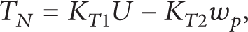
where U = k
f
f is phase voltage of stator, and k
f
= 4.4 is gain from frequency to voltage, KT1 = (3N/2πR)k
f
= 4.82,
Torque balance equation is
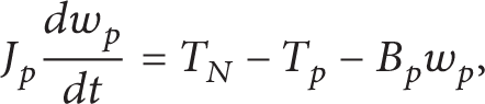
where T P = P h D p is load torque, and P h is system pressure (actually, output pressure of the pump), D p is displacement of the pump, J P is total inertia referred to motor shaft, roughly equal to 0.2 kgm2, and B P is total viscous damping coefficient, about 0.01 Nms/rad.
Equations (1)–(3) can be combined and Laplace transformed to yield

where Kv2 = k u k f KT1/(KT2 + B p ), Kv1 = D p /(KT2 + B p ), ω bp = (KT2 + B p )/J p , and actual rotary speed of electric motor is n p = 60w p /(2π). This transfer function indicates that the inverter-motor link is a first-order inertia element, and electric motor speed increases with increasing input voltage u p and decreasing system pressure P h . Hence the actual flow of the variable speed pump is

where Qp0 = D p w p is unload flow of the variable speed pump and C tp is total leakage coefficient of the pump.
3.2. Bypass Valve Control Circuit
The bypass valve PFV works at leaking status and its flow equation is given by

where I l is input current of PFV, C sv is the constant of PFV, ω sv and ξ sv are hydraulic natural frequency and damping ratio of PFV, respectively, Q l and Ql0 are actual flow of PFV, respectively, and K vl and K cl are flow gain and flow-pressure coefficient of PFV, respectively.
3.3. Valve-Pump Parallel Control Motor Link
Under the leaking parallel valve control mode, the total system continuity equation is
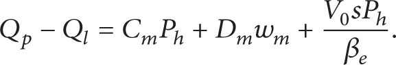
Torque balance equation of hydraulic motor is

where J is total inertia referred to shaft of hydraulic motor and B m is vicious damping coefficient. T L is load torque.
Combining (5)–(8), the open loop dynamic equation of the proposed system in leaking valve control is

where C
l
= C
p
+ C
m
+ K
cl
,
The valve-pump parallel control will switch to the single pump control when PFV is closed, Ql0, and K cl will be zero in (9), so the open loop dynamic equation of the proposed system under the pump control mode is given by [11, 12]. Consider

where
We note that (9) and (10) are similar, so the pump control mode can be regarded as a special case of valve-pump parallel control mode.
The rotary encoder responds fast and could be regarded as a proportional element

where K m is feedback gain, u m is feedback voltage of encoder, and n m = 60w m /(2π) is rotary speed of motor.
The proposed systems in pump control and leaking valve control are corrected by internal links, respectively, that is, K mI /s, K lI /s. So the compensated open loop transfer functions of the proposed system in pump control and leaking valve control are, respectively, given by
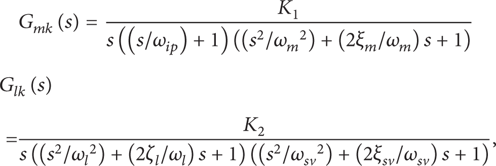
where K mI , K lI , and K rI are internal gains, and K1 = 60K mI Kv2K m /(2πD m ) and K2 = 60K lI K vl K m /(2πD m ) are compensated open loop gains of the proposed system in pump control and leaking valve control, respectively.
3.4. Total System Mathematical Model
Combining above three links, the block diagram of the proposed system in closed loop is obtained, as shown in Figure 3, and system parameters are listed in Table 2.
Parameters of the total system.


Block diagram of the proposed system (note: subscript “m/l” represents “m or l”, resp.).
From Table 2, we note that ω m = ω l < ω bp ≪ω sv , so the hydraulic natural frequency is the lowest break frequency and dominates dynamic performance of the total system, so these high frequency loops in (12) can be omitted. According to stable criterion, and for getting appropriate amplitude and phase margin, these compensated open loop gains should satisfy the following relations: K1 ≤ ω m ξ m , K2 ≤ ω l ξ l , so we set K mI = 1.5, K lI = 15. (Note that these values are estimated conservatively, because damping ratios vary widely.)
4. Low-Speed Performance Analysis
4.1. Theory Basis
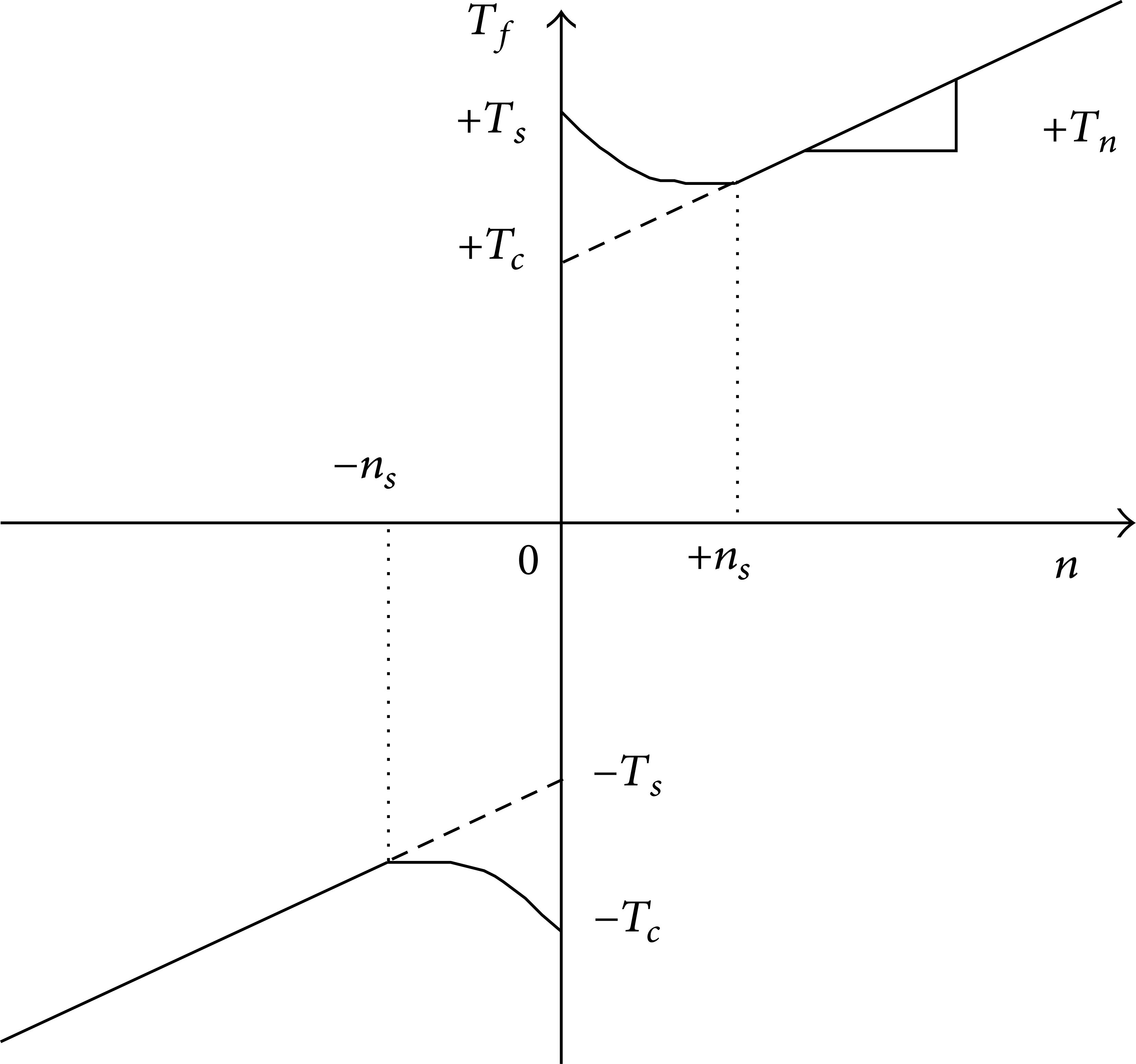
There are many influence factors on low-speed performance of hydraulic motors, such as internal factors (motor displacement ripple, leaking ripple, and friction torque) and external factors (flow and pressure ripple of oil source, load disturbance), but the principal factor is friction torque. Friction is known as a complex nonlinear physical phenomenon and could be described by static models or dynamic models [13–15]. Figure 4 and (13) present a normal static model of friction torque, which takes stiction, coulomb friction, viscous friction, and Stribeck effect which is described by the third item of (13) into account. Consider

where T e is external torque, T s is static torque, T c is Coulomb friction torque, n is relative speed, T n is viscous friction coefficient, n c is Stribeck speed, and sgn(n) is sign function.
A normal friction model with Stribeck effect.
Stribeck effect is used to describe the friction behavior at low speed [16]. As shown in Figure 4, the friction torque is a function of speed n and decreases with increasing speed at the region of small speed (|n| < n s ). This effect terribly affects the low-speed stability of hydraulic motors. Some previous studies [17, 18] show that the necessary condition of keeping low-speed stability is

where K ce is system total leaking coefficient which represents C t in (9) or C t in (10), B = dT f /dn is damping coefficient of friction torque, and other parameters are defined as former. At the region of small speed, the slope between friction torque and speed is negative due to the Stribeck effect; that is, B < 0.
The viscous damping coefficient B m is usually very small, so increasing system total leaking coefficient K ce and inertia J will improve the stability.
In Figure 4, n s is called critical speed. Hydraulic motor speed will oscillate below this speed, which is often called stick-slip phenomenon, and the oscillation will disappear above this speed. n s could be given by [18–20]

where K is system stiffness and ξ is system damping ratio. So increasing K, J, and ξ will obtain lower critical speed. ξ could be given by [21]

It is obvious that damping ratio, ξ, is associated with total leaking coefficient K ce and damping coefficient of friction torque B. Increasing K ce will increase ξ and lead to lower critical speed. In addition, ξ acts terrible nonlinear at low-speed region. As shown in Figure 4, the minus value of B becomes larger and ξ becomes smaller as speed decreases at the small speed region, which causes higher probability of oscillation and more difficulty in getting lower critical speed [22].
In addition, hydraulic pumps cannot work below its minimum stable speed, or it will cause severe flow and pressure ripple and the electric motor cannot supply adequate torque to control the pump under comparatively low frequency, especially at start and stop stages.
Based on above analyses, the leaking parallel valve control is employed to start and stop stages with low speed. This method has the following benefits.
The pump could work at a stable speed, which enables the flow of oil source to be more stable and electric motor to output adequate torque.
Increasing total leaking coefficients and damping ratios by adding leakage controlled by the valve helps to enhance low-speed stability and obtain lower critical speed.
Hydraulic motor speed decreases with increasing the valve opening, and damping ratios variation resulting from the change of valve opening is just opposite to that of damping ratios at low-speed region discussed previously. It could compensate the reduction of damping ratios due to the friction negative slop, which contributes to lower critical speed.
4.2. Simulation Model
Figure 5 shows the simulation model of the system in leaking parallel valve control, which is set up on the AMESim platform according to the schematic in Figure 1. AMESim is professional software used for multidisciplinary simulation in a uniform graphical environment, widely used in the field of automobile, hydraulic servos [23], aerospace engineering, and so forth. A simulation on AMESim is needed to go through four steps: sketch > submodels > parameters > simulation.

Simulation model on AMESim.
Key components on AMESim are set as in Table 1. FP04 is used to set the characteristics of the hydraulic fluid, in which the effective bulk modulus of fluid is 1400 MPa. To simulate total leakages of pump and motor C t , a fixed orifice is parallel connected to the high-pressure chamber of motor and its characteristic flow rate is set to 1 L/min/MPa. The rated input of the inverter is 10 V corresponding to maximum speed of eclectic motor and the rated input of the PFV is 40 mA corresponding to maximum opening. A friction model with Stribeck effect [24] is applied to simulate the friction behavior of hydraulic motor at low speed. We build a mode controller, which can switch between pump control mode and leaking control mode in the regulation process.
4.3. Verification
As discussed previously, hydraulic motors cannot work at low speed in variable speed hydraulic systems because pump should work above its minimum stable speed. For highlighting advantages of the leaking parallel valve control in improving low-speed performance, we even assume that the pump could work at any low speed in following simulations. We adapt the friction model with Stribeck effect shown in (13) and make the following settings: T s = 700 Nm, T c = 500 Nm, T v = 0, and n s = 10 r/min.
4.3.1. Low-Speed Performance in Open Loop Control
This part is carried out in open loop control for avoiding stability problem caused by closed loop control. Figure 6 shows influences of Stribeck effect on friction torque and hydraulic motor speed when the system is in pump control. In the process, pump flow increases from zero to 7.2 L/min as the inverter input increases from zero to 2 V in 10 seconds. It is obvious that, after adding Stribeck effect, the transition from static torque to Coulomb friction torque is exponential not instantaneous and the low speed of hydraulic motor is unstable. All those prove that the friction model could well simulate actual friction existing in hydraulic motors. Figure 6(b) also indicates that single pump control cannot assure low-speed performance.

Influences of Stribeck effect on friction torque and motor speed in pump control.
Figure 7 shows influences of different preopenings on start performance when the system is in leaking valve control. Figure 7(a) shows control signals of the valve and inverter. Keeping the control signal of inverter constant (u p = 2 V corresponding to n p = 600 r/min and Q p = 7.2 L/min), the control signal of the valve, respectively, decreases from 8 mA, 20 mA, and 32 mA to zero, corresponding to preopening decreasing from 20%, 50%, and 80% to zero, respectively. The red curve (0% preopening) is the control signal of inverter when the system is in pump control. Figures 7(b) and 7(c) indicate that total leakage coefficients and damping ratios in leaking valve control vary wildly with the valve inputs and reach maximum at the beginning of start. As shown in Figure 7(d), compared with the pump control, the leaking valve control could basically overcome the influence of Stribeck effect and obtain sound low-speed stability; in addition, could control start time and acceleration by regulating the preopening, the ruler is that greater preopening produces greater lag and acceleration. Using leaking control at the stop stage will also obtain above similar property here which is unnecessary to be verified in detail.

System response in leaking valve control.
According to (14)–(16), increasing inertia J could also improve system low-speed performance, which is verified in Figure 8. On the other hand, increasing J will reduce system natural frequency which leads to slow response, more space needed, and weight and cost increase. Therefore, increasing leakages controlled by valve is more flexible and economical compared with increasing inertia.
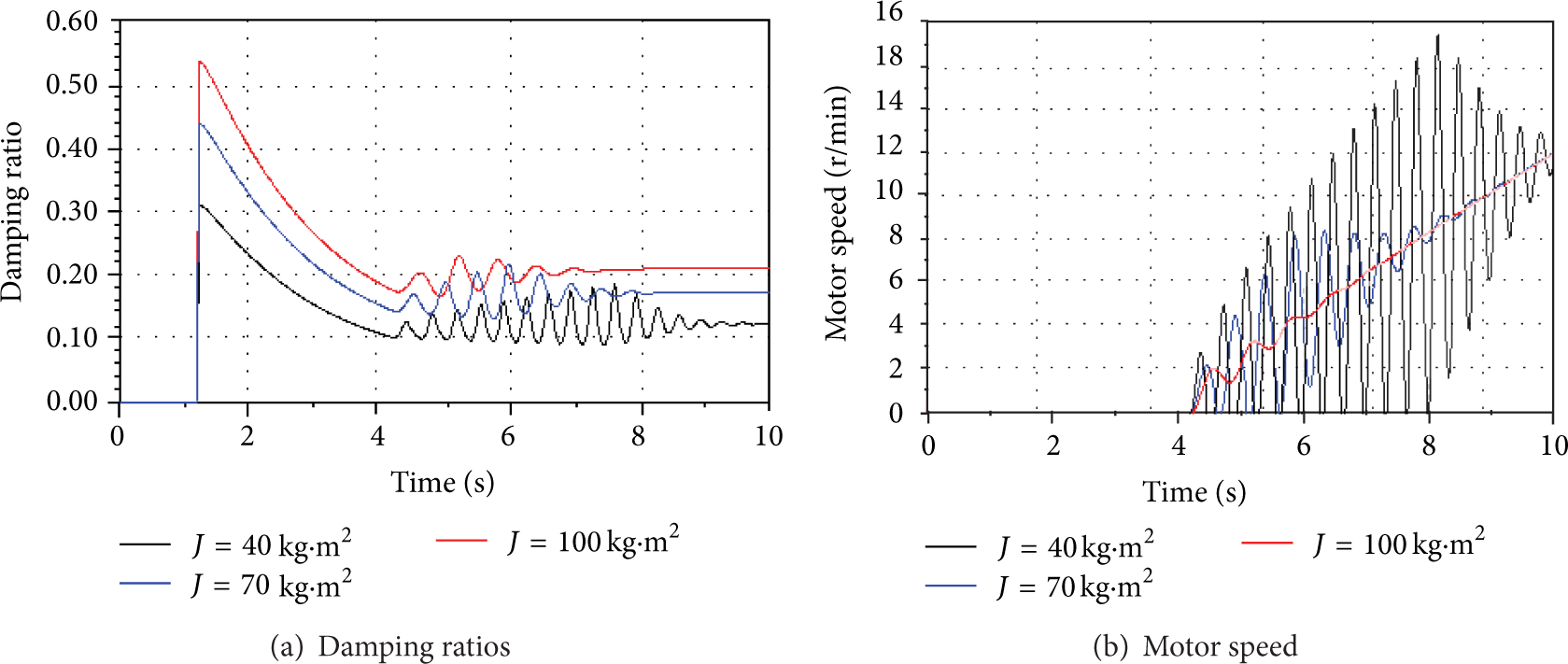
Influence of inertia on damping ratios and hydraulic motor speed in pump control.
4.3.2. Low-Speed Performance in Closed Loop Control
This part is carried out in closed loop control. Control modes are switched according to the desired speed n (n = u m /K m , nmax = 30r/min). When 0 ≤ n ≤ 12, the leaking valve control mode is applied; at other stages, the pump control mode is employed. The switch point 12 r/min is determined by deviation of the flow produced by the pump working above its minimum stable speed (500 r/min) and leakages of pump and hydraulic motor. Therefore, set inverter input to 2 V, corresponding to pump initial speed of 600 r/min and flow of 7.2 L/min. The preopening of PFV should be set to ensure that the flow leaks out entirely. Hence, the initial current of PFV is 14 mA, corresponding to 35% of opening. Figure 9 shows dynamic response in a duty circle in closed loop control.

System response in closed loop control in a duty circle.
At start and stop stages, compared with the system in single pump control, the system in leaking valve control achieves good low-speed performance and good tracking (shown in Figure 9(a)), and could basically avoid pressure impact at start and stop (shown in Figure 9(b)), and has more stable and suitable damping ratios, which increase with decreasing speed at the start and stop stages and reach maximum value (shown in Figure 9(c)).
Figures 9(d) and 9(e) show that both the variations of valve input and the pump speed match previous supposition without mutation during the closed loop control; that is, PFV input decreases with increasing desired motor speed at start and acts contrarily at stop; meanwhile the pump still works above its minimum stable speed, has a fixed speed at start and stop, and varies with the desired motor speed at other stages.
Figure 9(f) shows that the variable speed pump supplies total flow and PFV only leaks out minority of flow at start and stop stages, so the proposed system possesses comparatively high efficiency while achieving good low-speed performance. Moreover, the proposed system will be more efficient if the maximum speed rises. That is because the maximum flow corresponding to maximum speed is supplied by the pump not the valve which only works at start and stop stages and leaks few flow.
5. Conclusions
This paper presents a new variable speed hydraulic system in leaking parallel valve control; the following conclusions can be obtained.
Compared with traditional variable speed pump control systems, the leaking parallel valve control systems share the same natural frequency but have greater total leaking coefficients and damping ratios which contribute to improving low-speed stability and achieving lower critical speed.
The increase of damping ratios caused by leakage controlled by the valve just compensates the reduction of damping ratios due to the friction negative slop, which further enhances low-speed performance.
Increasing leakages controlled by valve is more flexible and economical compared with increasing inertia.
In the whole regulation process of closed loop control, the proposed system achieves good low-speed performance and basically avoids pressure impact at start and stop stages and has more stable and suitable damping ratios; moreover, the pump provides total flow and the valve only leaks few flow, so the proposed system possesses comparatively high efficiency.
This method is also available for variable displacement pump control systems for improving system low-speed performance.
Conflict of Interests
The authors declare that there is no conflict of interests regarding the publication of this paper.
Footnotes
Acknowledgments
This work is supported in part by the National Nature Science Foundation of China (51175497) and the Qing Lan Project of Jiangsu, China.