
Abstract
In order to study the influence of splitter blades on double suction centrifugal pumps two impellers with and without splitter blades were investigated numerically and experimentally. Three-dimensional turbulence simulations with and without full cavitation model were applied to simulate the flow in the two pumps with different impellers. The simulation results agreed with the experiment results and the internal flows were analyzed. Both the numerical and experimental results show that by adding splitter blades the hydraulic performance and the cavitation performance of the pump are improved. The pump efficiency is increased especially at high flow rate condition. The pump high efficiency area is extended dramatically. At the same time since the splitter blades share some part of the blade loading, the pump critical NPSH value is decreased. Obvious pressure increase and velocity decrease at blade suction surface near leading edge were observed in the pump impeller with splitter blades. And the pump cavitation performance was improved consequently.
1. Introduction
Double suction centrifugal pump is widely used in irrigation project, water supply, and drainage. The double suction centrifugal pump has long-time running under high flow rate conditions. As a result it is easy to suffer low efficiency, easy cavitation, and low stability for the double suction centrifugal pump. Pump impeller designed with splitter blades may be an effective way to improve the pump performances.
Hydraulic development of pump encounters two main problems. One is stability problem which is mainly caused by pressure fluctuation due to unsteady internal flow conditions. The other is cavitation problem induced by low pressure flow region of the pump flow. It has been found that splitter blades are helpful to improve the pump performances including efficiency, cavitation, and stability. For instance, ХЛОПЕНКОВП [1] studied centrifugal pumps with different splitter blades and found that splitter blades can increase pump efficiency and head and can improve pump cavitation and noise performances. Kergourlay et al. [2] simulated the internal flow of centrifugal pump with and without splitter blades. They compared the numerical results with the experiments and affirmed a positive role of the splitter blades in internal flow improvement and hydraulic performance improvement. Solis et al. [3] reduced pressure fluctuations by adding splitter blades to the original impeller and increasing the radial gap between the splitter impeller and the volute tongue. Cui et al. [4] predicted the cavitation performance of a centrifugal pump with splitter blades and found that the pump is cavitation free under design condition. At the same time the cavitation region is shrinking under off-design condition and the pump cavitation performance is improved. Thai and Lee [5] simulated the internal flow and found that the splitter blades have obvious effects on both pressure and velocity distributions in the centrifugal pump. Gui et al. [6] found that the splitter blades are also useful for minicentrifugal pump. By using splitter blades the blade-to-blade low velocity region was suppressed and the unsteady flows near the volute casing tongue were also suppressed.
Splitter blades are applied not only in pump impellers but also in other turbomachines and are proved to be beneficial for performance improvement [7, 8]. However, according to Gölcü et al. [9], the splitter blades must be designed carefully with reasonable length and deviation. Otherwise they may cause great turbulent fluctuation in impeller channel which has a great effect on the stability impeller outlet flow. Gölcü et al. [10, 11] found that the splitter blade length and blade number were important and took them as optimization parameters to optimize a deep well pump. Yuan et al. [12] also studied the splitter blade length effect on the flow in a low specific speed centrifugal pump by both simulation and experiment. The velocity at the impeller outlet is more uniform and the small-flow instability is improved effectively in impeller with long, mid, and short splitter blades. Shigemitsu et al. [13] studied different splitter blade parameters of the low specific speed centrifugal pump impeller. And they developed a design method for impeller with splitter blades including how to select splitter blade number, the off-setting angle, the inlet diameter, and the deflection angle.
In a word the splitter blades have important influence on the pump internal flow. Both velocity and pressure distributions in the impeller can be improved by adding splitter blades designed carefully. As a result the pump performances, not only the head and efficiency performance but also the cavitation and stability (pressure fluctuation) performance, can be improved. The main focus of our work is to investigate the cavitation performance of a double suction centrifugal pump with splitter blades. The research was performed by using both flow simulations and experiment tests. The experiment tests give the cavitation results and validate the flow simulation method, while the validated flow simulation gives the flow details of the cavitation performance. In the following section the flow simulation method is described first. Then both experiment and numerical results of a double suction centrifugal pump with and without splitter blades are compared and the cavitation performance is discussed. At last conclusions are provided.
2. Numerical Simulation
A three-dimensional turbulence flow simulation technique for full passage of a double suction centrifugal pump was applied to simulate the internal flow field. The commercial software ANSYS was used to conduct the full passage numerical simulations. The ANSYS BladeGen was used for the three-dimensional flow passage generation. The flow passage was then imported into the ANSYS ICEM CFD for grid generation. And the ANSYS-CFX 14.0 was used for the flow solution.
2.1. Numerical Methods
The cavitating turbulent flow was simulated using the ANSYS-CFX based on the Reynolds-averaged Navier-Stokes (RANS) equation with the SST k-ω turbulence model developed by Menter [14]. The mixture model for vapor/liquid two-phase flows was used. The full cavitation model [15] developed by Singhal et al. was used here. The momentum and continuity equations were solved simultaneously by using a direct coupling method. The high order resolution scheme was used for the convection terms with the central difference scheme used for the diffusion terms in the governing equations. A frozen rotor model was used for the pump domain including both stationary and rotation parts.
2.2. Pump Geometry and Grid Generation
The simulation object is a double suction centrifugal pump with and without splitter blades, which is named conventional and compound pump, respectively, hereafter. The rated revolution speed is n = 2950 r/min, and the design flow rate is Q
d
= 75 L/s. The blade number of the conventional impeller without splitter blades is Z = 6. The blade number of the compound impeller with splitter blades is Z
c
= 8, four of which is the number of splitter blades. The inlet diameter of the splitter blades at the shroud is 0.077 m. And the inlet diameter of the splitter blades at the hub is 0.07 m. The splitter blades outlet position and dimension are the same as the long blades. Both impellers have the same outlet diameter D2 = 0.206 m, outlet width b2 = 0.018 m, inlet diameter at shroud D
s
= 0.062 m, and inlet diameter at hub D
h
= 0.041 m. Figure 1 shows the geometry of both the conventional and compound pump impeller. The specific speed is defined by

Impeller geometry of both conventional and compound impellers.
The simulation domain contains inlet section, suction case, impeller, volute case, and outlet section, as shown in Figure 2. An unstructured tetrahedron grid was applied to the whole domain. Grid cluster was used near the blade surfaces and the volute tongue. The grid independence was checked and a mesh grid around 2.5 million cells was determined for the final simulation of both conventional and compound impeller.

Simulation domain and grid generation.
2.3. Boundary Conditions
Three conditions with different flow rate of 0.7Q d , 1.0Q d , and 1.3Q d were simulated. For steady simulation without cavitation, mass flow rate was specified at the inlet boundary and static pressure was given at the outlet boundary. For cavitation simulation, total pressure was specified at the inlet boundary for the convenience of the cavitation condition adjustment. And mass flow rate was given at the outlet boundary. Adhesion condition was satisfied at all the end walls.
3. Results and Discussion
3.1. Steady Simulation Results
The simulation and experiment efficiency and head curves of double suction centrifugal pump with and without splitter blades were shown in Figure 3. It can be seen that the splitter blades increase the pump efficiency especially under high flow rate conditions. The efficiency improvement is more obvious with the flow rate increase. The maximum efficiency is also improved. And the high efficiency range of the pump is extended which is important for double suction centrifugal pump. The hydraulic performance is almost the same under low flow rate. In a word the splitter blades can improve the hydraulic performance dramatically under high flow rate for double suction centrifugal pump.
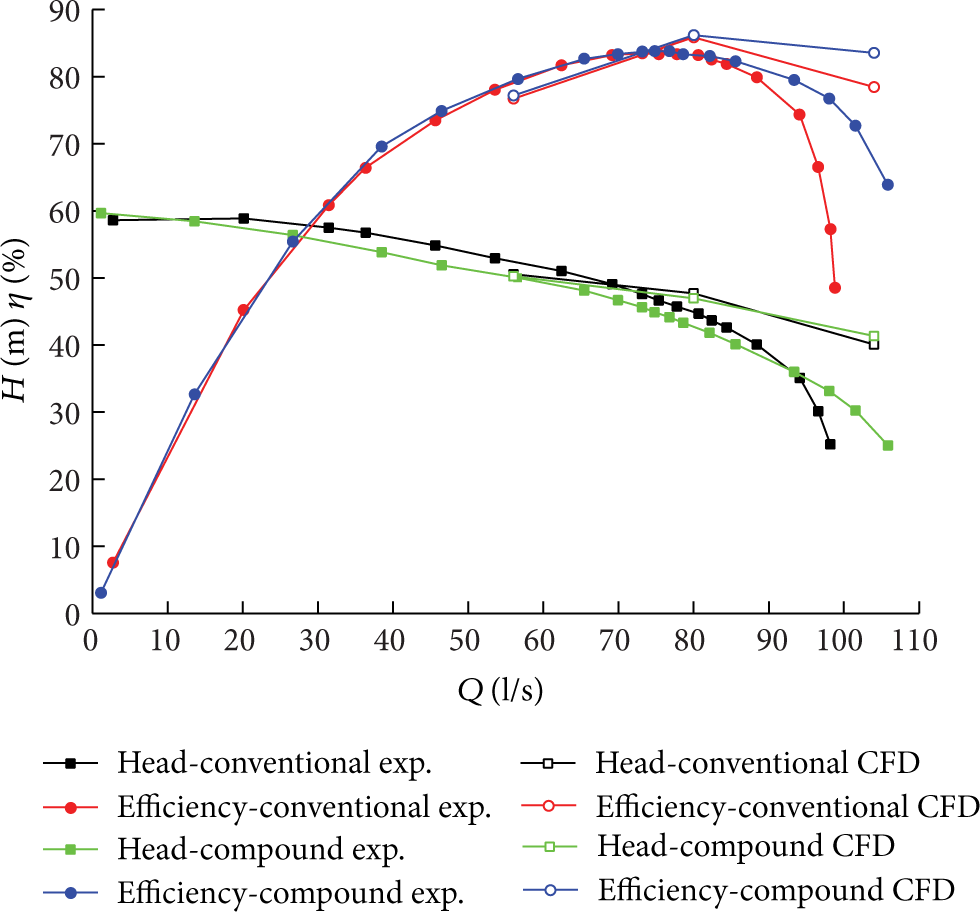
Simulation and experiment efficiency, head curves of double suction centrifugal pump with and without splitter blades.
3.2. Cavitation Simulation Results
3.2.1. Cavitation Performance
In experiment the inlet pressure was changed to lower step by step to find the critical NPSH which was defined when the head decreases 3%. In the numerical simulation the same process was simulated and the results are shown in Figure 4. It can be seen that sudden drop of the pump head appeared when the inlet pressure decreased to a specific level. The dotted line in Figure 4 indicated the 3% head drop and the corresponding NPSH value is the critical one. Figure 5 shows the critical NPSH curves from simulation and experiment results at different flow rate conditions for conventional and compound pump. It can be seen that the compound impeller with splitter blades postpones the critical cavitation apparently, especially at high flow rates. In fact at 70% design flow rate condition the calculated critical NPSH of compound pump decreases 16.7% compared with the conventional pump. And at 130% design flow rate condition the value increases to 32.5%.
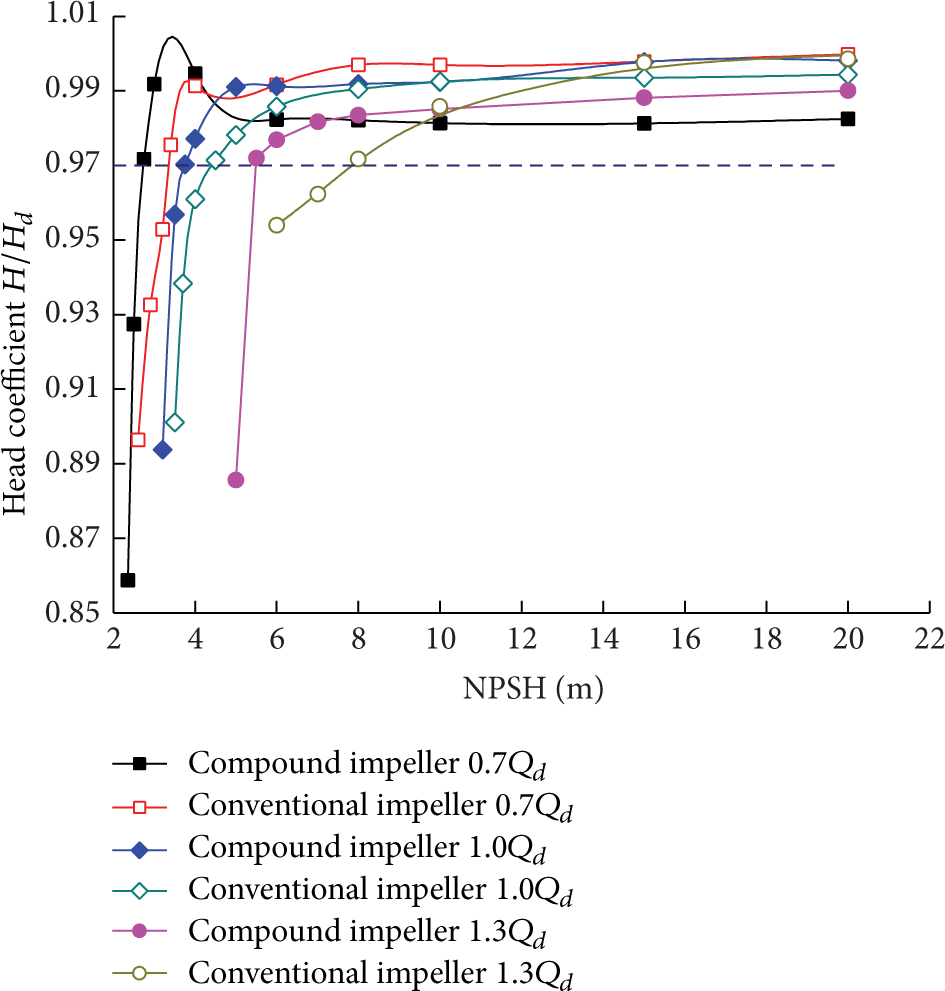
Simulated NPSH curves at different flow rate conditions for conventional and compound pump.

Critical NPSH curves from simulation and experiment results at different flow rate conditions for conventional and compound pump.
3.2.2. Flow Field Analysis
The cavitation performance results show that the compound pump with splitter blades is better than the conventional pump without splitter blades, especially at high flow rate condition. In this section the above cavitation improvement was analyzed from the internal flow field viewpoint.
In pump the cavitation often takes place at the suction surface near the leading edge. Since the leading edge is always in the low pressure region, the pump cavitation performance can be improved by increasing the pressure at suction surface around the leading edge area. On the other hand the NPSH can be expressed as follows:

where λ1 is pressure-drop coefficient caused by absolute velocity change and hydraulic loss; λ2 is pressure-drop coefficient caused by flow around the leading edge; V0 is mean velocity at the blade inlet; and W is relative velocity in the impeller. For a specified flow rate V0 is constant and the NPSH is related to the relative velocity W. A small W is helpful to decrease the NPSH and improve the cavitation performance.
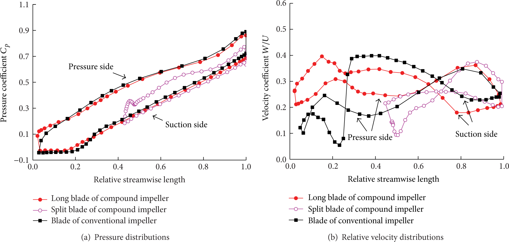
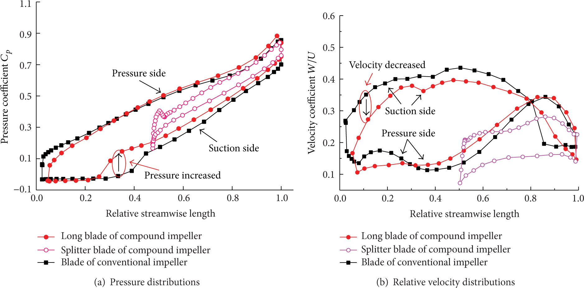
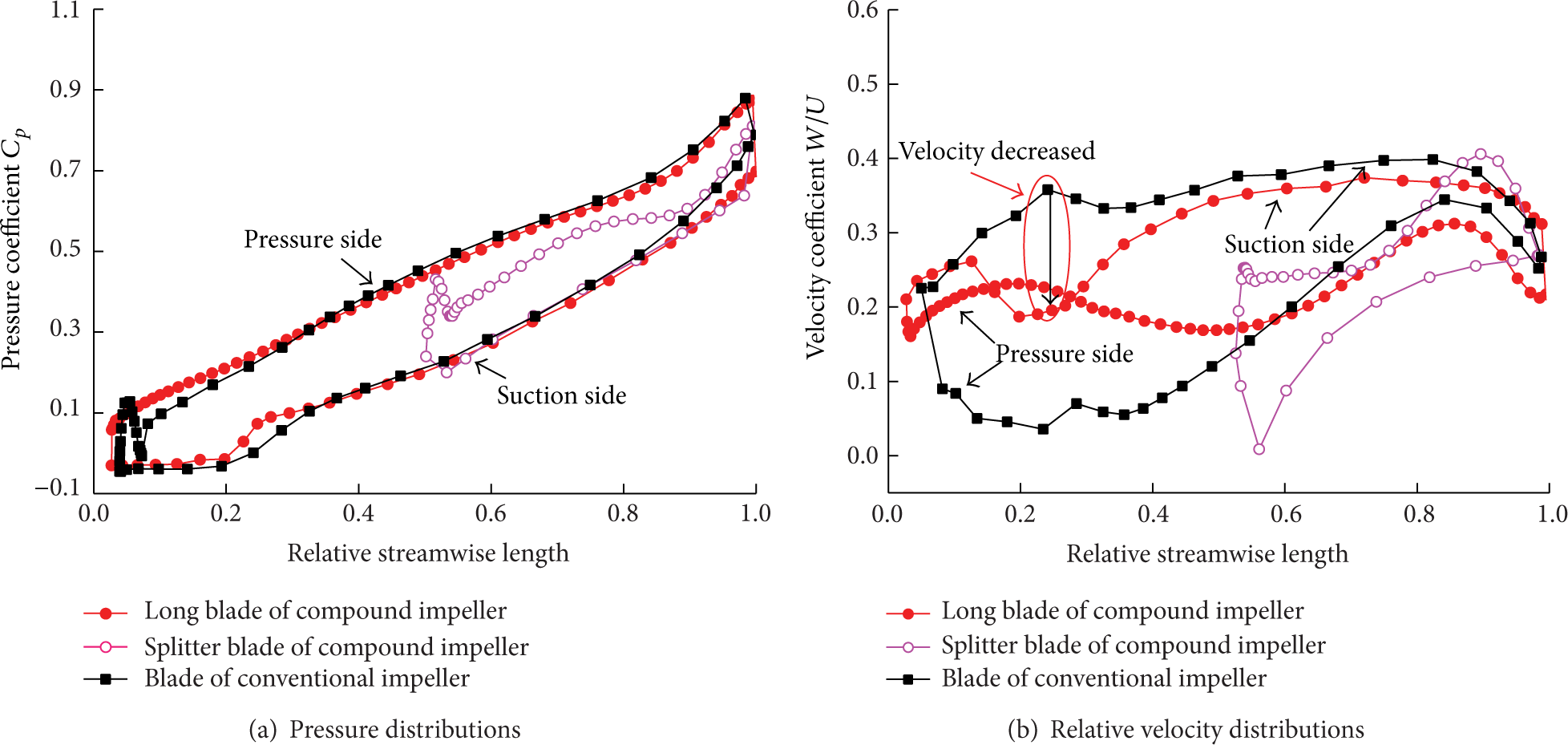
Both pressure and relative velocity distributions along blade surface streamline at different spanwise positions under design and 130% design flow rate conditions for both compound and conventional impellers were examined to explore the cavitation performance improvement by using splitter blades. In the compound impeller the pressure load on long blades was usually shared by the splitter blades as shown in Figure 6(a) to Figure 11(a). Low pressure load means high pressure at suction side and low pressure at pressure side which is helpful to improve the pump suction performance. At design flow rate condition no pronounced pressure or velocity improvement was found at 20% spanwise position as shown in Figure 6. However an obvious pressure increase and relative velocity decrease were observed at the suction surface near the leading edge in the compound impeller at 50% spanwise position as shown in Figure 7. And an obvious relative decrease was also observed in the compound impeller at 80% spanwise position as shown in Figure 8. At 130% design flow rate condition obvious pressure increase was found at both 20% and 80% spanwise positions as shown in Figure 9(a) and Figure 11(a). An obvious relative velocity decrease was observed at 50% spanwise position as shown in Figure 10(b). All the observed pressure increase and velocity decrease happened at the suction surface near the leading edge which indicated the improvement of the cavitation performance after using splitter blades and confirmed the cavitation performance results. Figures 12 and 13 show the water vapor distributions in both conventional and compound impellers under the same flow rate and inlet pressure condition. It can be seen that the water vapor area in compound impeller is obviously smaller than that of the conventional impeller at both design and 130% design flow rate conditions. The results were consistent with the above pressure and velocity discussions.
Pressure (a) and relative velocity (b) distributions along blade surface streamline at 20% spanwise position under design flow rate condition for both compound and conventional impellers.
Pressure (a) and relative velocity (b) distributions along blade surface streamline at 50% spanwise position under design flow rate condition for both compound and conventional impellers.
Pressure (a) and relative velocity (b) distributions along blade surface streamline at 80% spanwise position under design flow rate condition for both compound and conventional impellers.

Pressure (a) and relative velocity (b) distributions along blade surface streamline at 20% spanwise position under 130% design flow rate condition for both compound and conventional impellers.

Pressure (a) and relative velocity (b) distributions along blade surface streamline at 50% spanwise position under 130% design flow rate condition for both compound and conventional impellers.

Pressure (a) and relative velocity (b) distributions along blade surface streamline at 80% spanwise position under 130% design flow rate condition for both compound and conventional impellers.
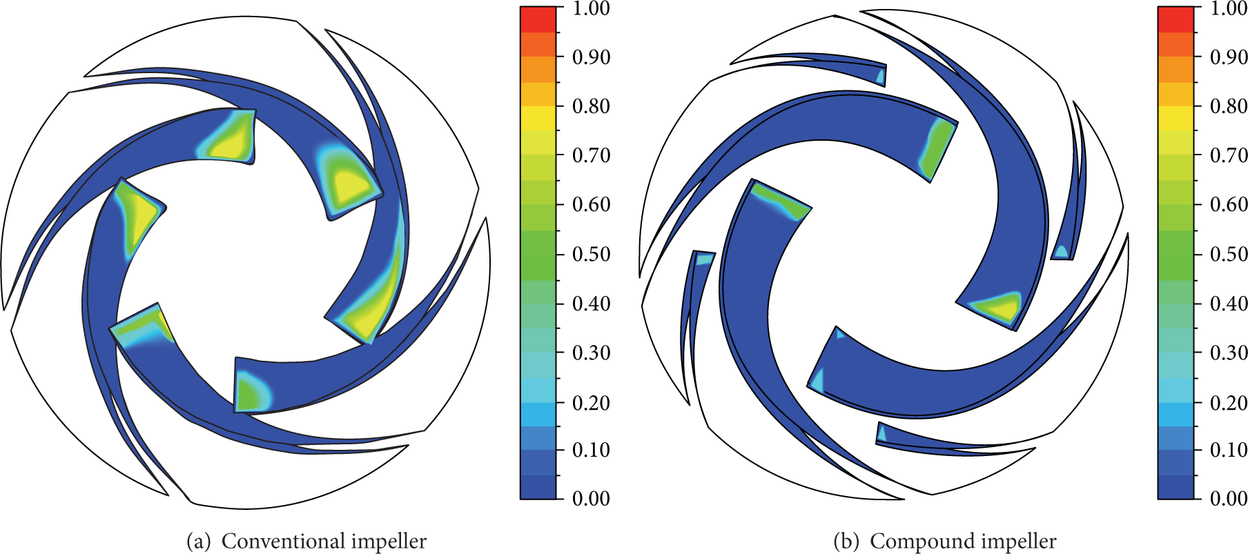
Water vapor volume fraction distributions of conventional impeller (a) and compound impeller (b) at design flow rate condition with 4 m inlet pressure.

Water vapor volume fraction distributions of conventional impeller (a) and compound impeller (b) at 130% design flow rate condition with 5 m inlet pressure.
4. Conclusions
Both numerical simulation and experiment test were performed on double suction centrifugal pumps with and without splitter blades. The hydraulic and cavitation performances were checked for the two pumps. The pump efficiency is increased especially at high flow rate conditions with splitter blades. The most important thing is that the pump high efficiency operating range is extended dramatically by adding splitter blades. The NPSH results show that the splitter blades can decrease the critical NPSH value of the double suction pump especially at high flow rate. The internal flow field tells us that the splitter blades can share the blade loading and improve the pressure loading distributions on blades. The pressure loading share between long blades and splitter blades is helpful for pressure increase and velocity decrease at suction surface near the leading edge which is useful to improve the pump cavitation performance. So a good design of splitter blades can improve not only the hydraulic performance but also the cavitation performance for double suction centrifugal pump.
Footnotes
Nomenclature
Conflict of Interests
The authors declare that there is no conflict of interests regarding the publication of this paper.
Acknowledgments
The authors are thankful for the support of Key Project of National Natural Science Foundation of China under Grant no. 51139007 and Young Project of National Natural Foundation of China under Grant no. 51209206.