
Abstract
A multicurved sheet metal surface for a skin structure has usually been manufactured using a conventional die forming process involving the use of both a die and a press machine in accordance with the product shape. However, such processes are economically inefficient because additional production costs are incurred for the development and management of forming tools. To overcome this drawback, many alternative processes have been developed; however, these still suffer from problems due to defects such as dimples and wrinkles occurring in the sheet. In this study, a new sheet metal forming process called the flexibly reconfigurable roll forming (FRRF) process is proposed as an alternative to existing processes. Unlike existing processes, FRRF can reduce additional production costs resulting from material loss and significantly reduce forming errors. Furthermore, it involves the use of a smaller apparatus. The methodology and applicable procedure of the FRRF process are described. Numerical forming simulations of representative multicurved sheet surfaces are conducted using FEM. In addition, a simple apparatus is developed for verifying the feasibility of this process, and a doubly curved metal is formed to verify the applicability of the reconfigurable roller, a critical component in this forming process.
1. Introduction
In recent years, various multicurved sheet metal surfaces are being increasingly used for manufacturing the skin structures of automobiles, ships, airplanes, and so forth owing to growing consumer and manufacturer demand. A multicurved sheet metal surface has generally been manufactured using the conventional die forming process, which involves the use of a die and a press machine tool to match the product shape. Although this process is ideal for ensuring good forming quality and productivity, it is not economically efficient because of additional production costs incurred for the development and management of a forming die set. Furthermore, this process cannot be applied to small-quantity batch production as is commonly required in the aerospace and shipbuilding industries, unlike in the construction industry.
To overcome these limitations, a flexible forming concept requiring only one forming die has been developed. New sheet metal forming processes have also been introduced to avoid unnecessary costs. A flexible forming concept using discrete punches was first proposed by Japanese researchers. In 1969, Nakajima proposed a reconfigurable die consisting of thin wires bonded together using a retainer; in this system, the positioning of a number of thin wires could be controlled using an ultrasonic vibrator [1]. Olsen et al. from MIT suggested a mechanical design and shape control algorithm for a discrete die surface (DDS) system and developed reconfigurable tooling for flexible fabrication [2, 3]. Zhang et al. proposed a multipoint sandwich forming (MPSF) process involving the use of a polyurethane upper die, a workpiece, a polyurethane interpolator, a die sheet, and a multipoint die; however, this process suffered from some inherent weakness in the design of the machine owing to the use of disposable parts such as the upper die and die sheet [4, 5]. Yoon et al. proposed an incremental roll forming method using a movable center roller and four adjustable supporting rollers as a forming tool [6, 7]. Park et al. developed different types of forming processes such as the fluid dieless forming process involving the use of fluid or elastomer materials instead of metallic tooling [8]. Li et al. explored a multipoint forming (MPF) process using densely distributed discrete punches as shown in Figure 1 [9, 10].

Multipoint forming process (a type of flexible forming process for sheet metal).
Among these flexible metal forming processes, MPF is more preferable for both thick plates and thin sheet metals having a gradual gradient and curvature distribution. However, it may produce some defects such as dimples and wrinkles owing to irregular gaps between the sheet metal and the discrete punches as illustrated in Figure 2. In addition, it requires additional machining outside of the formed region on the sheet metal, leading to material loss because of the discontinuous surface, as shown in Figure 3. To overcome these inherent drawbacks, studies have investigated the use of an elastic pad such as a urethane pad for smoothing the discrete forming surface [11, 12]. Currently, a study is focusing on elastic recovery compensation for the type of precise machining usually required in the aerospace industry [13, 14].
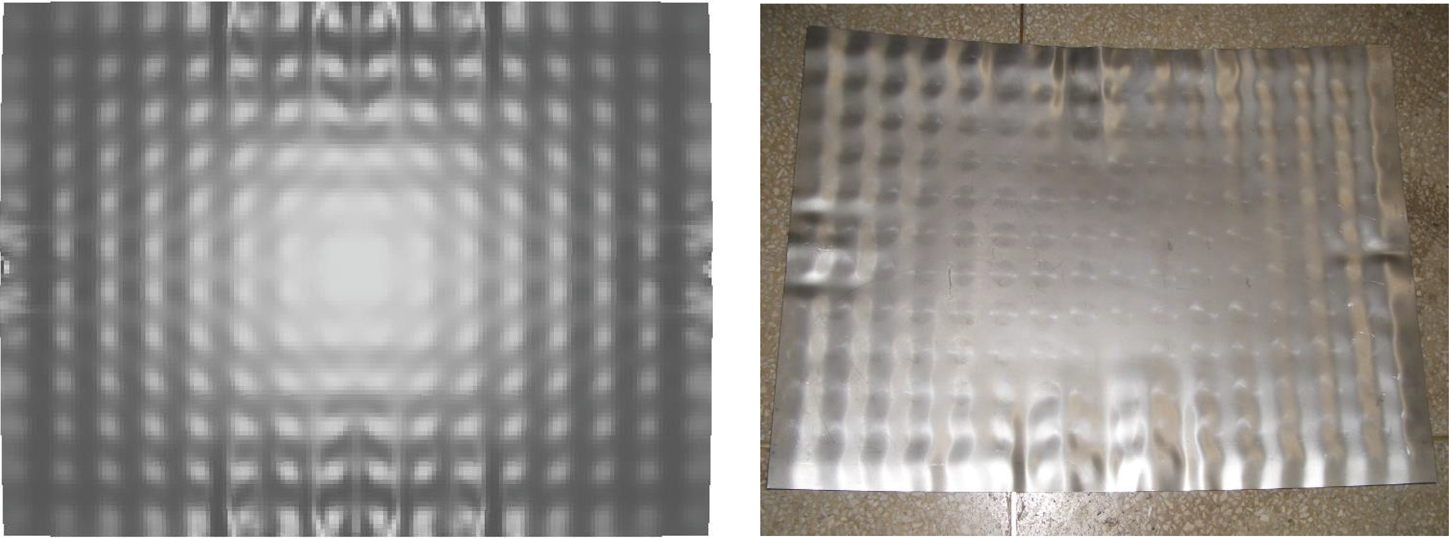
Numerical (left) and experimental (right) examples with dimples and wrinkles formed by using multipoint forming process.

Straight effect incurring the material loss.
In this study, a new sheet metal forming process called the flexibly reconfigurable roll forming (FRRF) process is proposed as an alternative to both the existing flexible forming process and the conventional die forming process for a multicurved sheet metal surface [15, 16]. As shown in Figure 4, this process uses adjustable punches as well as upper and lower reconfigurable rollers as forming tools for manufacturing an unrestricted blank size in the longitudinal direction, as in the typical roll forming process. Furthermore, motors are used to apply sufficient torque to both the adjustable punches and the reconfigurable rollers. Unlike the existing flexible forming processes, FRRF can reduce the additional production costs resulting from material losses and considerably minimize forming errors such as dimples and wrinkles because of the relatively continuous forming surface; furthermore, it requires smaller apparatus compared with other flexible forming processes. The methodology and applicable procedure of the FRRF process are described. Numerical forming simulations of representative multicurved sheet surfaces are conducted using FEM. In addition, a simple apparatus is constructed for verifying the feasibility of this process, and a doubly curved sheet metal is formed for verifying the applicability of the reconfigurable roller, which is a critical component in this forming process.

Schematic diagram of flexibly reconfigurable roll forming apparatus.
2. FRRF Process for Sheet Metal Forming
The flexibly reconfigurable roller is the most crucial part of this apparatus, and it allows the manufacturing of various shapes without remaking and revising the solid dies. Its shape can be changed in the vertical direction. Furthermore, as shown in Figure 5, its curvature can be adjusted using different heights of the multipunch array, which are controlled by the number of revolutions of the motor. In this apparatus, the number of motors used for adjusting the height of the punch arrays can be equal to the number of adjustable punches. Otherwise, one or more motors can be used to adjust the lengths of punches by installing a transmitter for reducing the development costs of the apparatus, as shown in Figure 5. Figure 6 shows the punch assembly and its mechanism. The curvature adjustable punch consists of an internal rod, an outer housing, and a roller guide. The internal rod and outer housing have an external and an internal thread, respectively, for adjusting the height of the curvature adjustable punch. The other part of the internal rod, which is not connected to the outer housing, is joined to the motor for torque transmission through gears. The opposite side of the outer housing has a roller guide that supports the consecutive bending of the reconfigurable roller. The roller guide is equipped with an easily replaceable bush; this is necessary because the bush is affected by mechanical abrasion despite its low-friction coating.

Schematic diagram of adjustable multipunch array.

Illustration of punch assembly and its mechanism.
To manufacture a multicurved sheet metal surface using the FRRF process, first, the adjustable punches are arranged for reconfiguring the rollers having particular curvatures. The initial blank is inserted between the reconfigurable rollers, and then the blank is formed by forcing it out via the rotation of the reconfigurable rollers, as in the typical roll forming process. In this procedure, the reconfigurable rollers are rotated by the forming roller motors on both of their ends. The shape of the multicurved sheet is determined by both rollers, whose curvatures are slightly different from each other. Various multicurved sheet metal surfaces can be manufactured based on the curvatures along both the transverse and the longitudinal directions, as shown in Figure 7. The curvature of the formed sheet metal in the transverse direction is related to that of the reconfigurable rollers, which are controlled by the heights of the multipunch array. On the other hand, the curvature of the formed sheet metal in the longitudinal direction is related to the differences in the applied thickness strains on the sheet metal, which arise from the difference in the size of the gaps between the upper and the lower reconfigurable rollers depending on the location of the reconfigurable rollers. For instance, the final product has a convex-type surface if the applied thickness strain on the center of the blank is larger than that at the edges during the forming process, whereas the reverse configuration is true for saddle-type surface. In the case of the twist-type, the applied thickness strain on one edge of the blank is larger than that at the opposite edge in the transverse direction.

Forming procedure of flexibly reconfigurable roll forming.
3. FE Simulations
In the FRRF process, the final sheet metal shape depends on the combination of the curvatures of the reconfigurable rollers, as mentioned in previous section. The forming location can be simply described as a piece of sheet metal, along with the upper and lower reconfigurable rollers, as shown in Figure 8. The geometrical shapes with respect to the sheet metal and reconfigurable rollers can be described in terms of quadratic curves, which indicate the neutral axis of the sheet metal and the rotation axes of the upper and the lower reconfigurable rollers. In Figure 8, the subscripts b, u, and l denote the blank sheet, upper reconfigurable roller, and lower reconfigurable roller, respectively. In this study, three design parameters that are used to describe the curvature of a multicurved sheet metal surface are defined for geometrical modeling: radius of curvature (R b,c ), included angle (θtip) between the center and the edge of the sheet metal, and eccentricity (e b ) of the neutral axis of the sheet metal. By suitably using these parameters, various multicurved sheet metal surfaces having quadratic curves can be made, such as arcs. This geometrical design method enables changes in the design and precision processing because modeling begins with the target shape of the sheet metal instead of the shape of the reconfigurable rollers. The curvature radius and included angle are used to determine the curvature and shape of the sheet metal along the transverse direction. Consecutively, different gaps between the reconfigurable rollers affect the curvature of the sheet metal along the longitudinal direction.

Geometrical design for flexibly reconfigurable roll forming.
Simulations are conducted to demonstrate the feasibility of the FRRF process using the geometrical design method. In this study, different design parameters are applied to simulations multicurved sheet shapes such as convex-, saddle-, and twist-type. Simulations for these representative multicurved shapes are implemented using ABAQUS, a widely used commercial software for finite element simulation. In these simulations, the radius of curvature (R
b,c
), included angle (θedge), and eccentricity (e
b
) are set at 1000 mm, ±2.86°, and 0, respectively, in the convex-type and saddle-type. The radius of curvature for the twist-type is 1200 mm. The reductions in thickness at the center and edge of the sheet metal for convex-type are 10% and 1%, respectively. The saddle-type is made by reverse configuration of convex-type. In the case of the twist-type, the reductions at one edge and opposite edge are 10% and 1%, respectively. The simulations can be classified into two phases. In the first phase, a piece of sheet metal is inserted between the reconfigurable rollers and held there. In the second phase, the reconfigurable rollers are rotated to push the sheet metal out. Figure 9 shows the simulation model for the convex-type. The vertically arranged reconfigurable rollers are split into numerous consecutive rings. In these simulations, each ring has a diameter and width of 10 and 2 mm, respectively. Every ring is positioned during the first phase, and each ring is arranged in the direction of the tangent along the quadratic curves, which are the rotation axes of the reconfigurable rollers. Thus, the total number of rings for the simulation is determined according to the values of the design parameters. During the simulations, the translational and rotational motions of the rings are performed along with the local coordinate system, in which the center of each ring is considered the origin. In other words, the origin of every ring is located on the quadratic curves. The number of revolutions of the reconfigurable rollers is decided depending on the length of the sheet metal along the longitudinal direction. In the simulation, Al 1050, a relatively soft material, is used as the sheet metal, and it is assumed to be an elastoplastic material. Its Young's modulus E, Poisson's ratio ν, yield strength, and ultimate strength are 69 GPa, 0.33, 125 MPa, and 135 MPa, respectively. The relationship of the exponential work hardening plastic material,

Example of FE model using flexibly reconfigurable roll forming.
Figures 10 and 11 show numerical results of the simulations for the representative multicurved sheet metal surface using the FRRF process. These results are obtained from forming simulations in which all of the rings are arranged in accordance with the respective quadratic curves and then rotated around their own axis for pushing the sheet metal out. All types of sheet metal shapes can be formed under the condition that the same numbers and sizes are used for the sheet metal and rings in the simulations. The convex-type curved sheet has high stress values close to the ultimate tensile stress compared with the other shapes because the curvatures along both the transverse and the longitudinal directions overlap at the center of the sheet metal. In contrast, the saddle-type curved sheet metal has a relatively lower stress compared with convex-type because the curvatures along the transverse and the longitudinal directions have opposite signs. The twist-type curved sheet metal has higher stress near the exit of the reconfigurable rollers owing to the complex stresses caused by bending and torsional strains. Although precise values of curvature of the deformed sheet metals are unpredictable, shape types of final product are predictable using the configuration of the applied thickness strains on the sheet metal. This configuration of the applied thickness strains is reflected in Figure 11. In these simulations, spring-back is not considered owing to focus on the feasibility of FRRF process. However, after sheet forming is involved, elastic recovery is observed in the formed side of sheet metal. Therefore, the fluctuation of stress and strain distribution on the sheet metal can also be observed. This is due to the fact that the blank is not constrained by forming tools unlike other bending technologies. As shown in Figure 10, no defects such as dimples and wrinkles, which are common in existing flexible forming technologies as previously described in Figure 2, are observed. Therefore, the proposed FRRF process is suitable for a forming multicurved sheet metal surface. Furthermore, it is relatively superior to previous methods because it does not involve any additional machining and the blank size is not restricted along the longitudinal direction.

Stress distribution of typical multicurved sheet metal surfaces obtained by using FRRF process.

Thickness strain of typical multicurved sheet metal surfaces obtained by using FRRF process.
4. FRRF Apparatus and Its Implementation
Figure 12 shows the pre-FRRF apparatus used for verifying the applicability of a reconfigurable roller. It consists of roller supporters, reconfigurable rollers, a geared motor module, and frames, as shown in Figures 12 and 13. This apparatus is used to produce a saddle-type curved sheet metal having a doubly curved shape because this surface is more suitable for describing multicurved sheet metal surfaces compared to other shapes. As shown in Figure 12, the roller supporters are made up of one part having a curved surface, in contrast with application of the adjustable punches, because this apparatus is only used to test the reconfigurable roller. The roller supporters are made of a material that is treated by high-frequency induction hardening for high hardness and by surface coating for low friction between the reconfigurable rollers and the supports. To support the reconfigurable rollers, the upper and lower roller supporters have grooved and curved sections having a radius of curvature of 1000 and 943 mm, respectively. These geometrical values for the roller supports are equal to the radii of curvature of the reconfigurable rollers during forming and are designed to make 1% and 10% reduction in thickness at the center and both edges of the sheet metal, respectively. The reconfigurable rollers are made of AISI 440 stainless steel having high modulus of elasticity (200 GPa) and yield stress (1.28 GPa); the solid bar-type rollers are treated by heat treatment for appropriate elastic behavior during forming, and each roller has a diameter of 10 mm as in the simulations. Although the reconfigurable rollers have already been used to test for several formings, they play a role as forming tools within their elastic range as shown in Figure 13(a). The roller motor module consists of gears, an electric motor, and couplings to provide sufficient torque to the reconfigurable rollers.

Pre-FRRF apparatus for verifying the applicability of reconfigurable rollers.
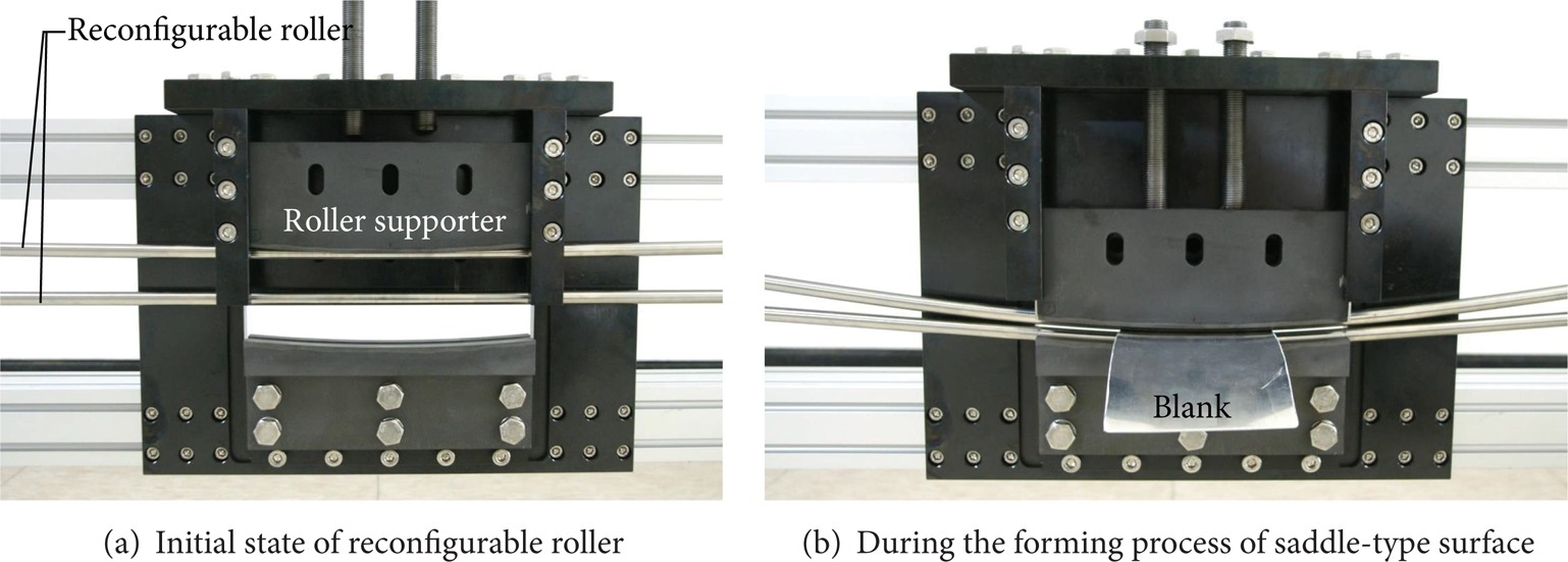
View of forming location of pre-FRRF apparatus.
In the forming test using the pre-FRRF apparatus, the forming procedure is carried out in two phases as in the simulations for producing a saddle-type surface. In the first phase, a blank material is held by manual setting because the roller supporters are already designed considering the geometrical relationship between the reconfigurable rollers and the roller supporters. In the second phase, the initial blank is formed into a saddle-type curved sheet by rotating the reconfigurable rollers as shown in Figure 13(b). This formed shape of the sheet metal is obtained from configuration of the applied thickness strains for the saddle-type surface as previously mentioned. As shown in Figure 14, the formed surface has no wrinkles and dimples, unlike in surfaces produced by previous flexible forming methods, as with the simulations. Furthermore, this process can reduce additional production costs because the blank size is unrestricted along the push direction of the sheet metal. The successful formation of sheet metal by the pre-FRRF apparatus suggests that this process is suitable for producing a multicurved sheet metal surface and that the roller materials used are suitable for application to the reconfigurable rollers.
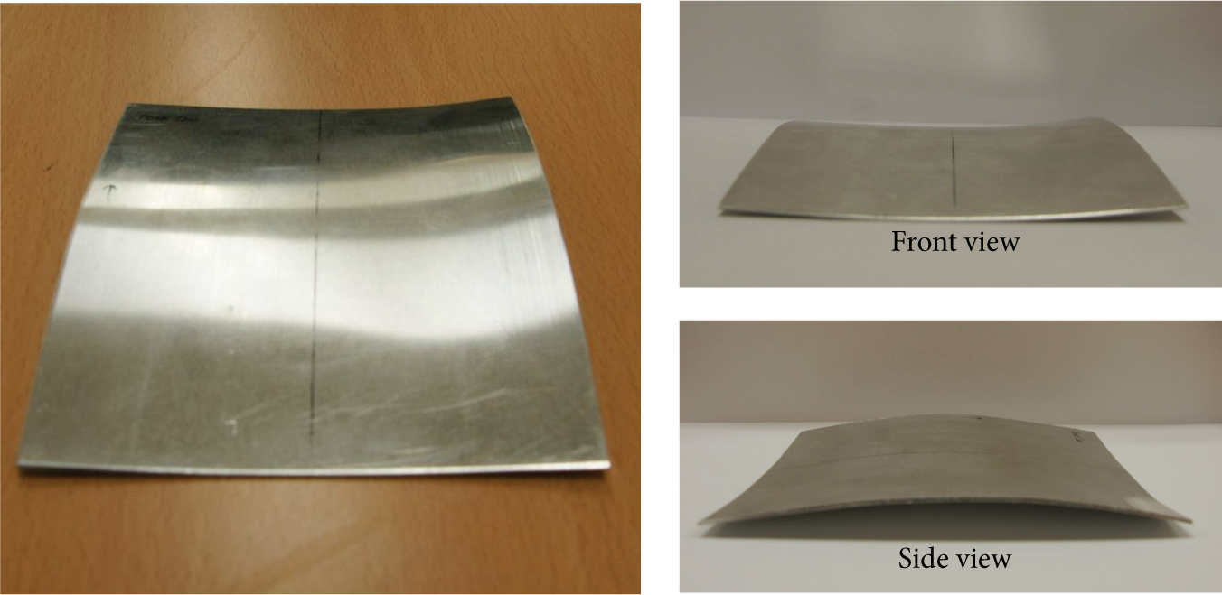
Saddle-type sheet metal formed by pre-FRRF apparatus.
5. Conclusion
In this study, the methods and procedures of the FRRF process for producing three-dimensional curved sheet metal surfaces were described, and FE simulations of representative multicurved sheet metal surfaces were conducted to evaluate the feasibility of this process. These simulations show that the FRRF process is suitable for manufacturing a multicurved sheet metal surface without defects such as dimples and wrinkles that otherwise incur additional production costs. This process can also reduce material loss that commonly occurs in existing processes because the blank size along the longitudinal direction is unrestricted. Therefore, this process is suitable for producing multicurved sheet metal surfaces.
A pre-FRRF apparatus was developed to experimentally verify the feasibility of the reconfigurable roller, an essential component in this process. The test results demonstrate that a reconfigurable roller having high modulus of elasticity can be used to form low-strength sheet metal without plastic behaviour. Furthermore, the FRRF process is suitable for manufacturing multicurved sheet metal surfaces and is a viable alternative to existing sheet metal forming processes for three-dimensional curved surfaces.
Conflict of Interests
The authors declare that there is no conflict of interests regarding the publication of this paper.
Footnotes
Acknowledgments
This work was supported by the National Research Foundation of Korea (NRF) Grant funded by the Korea Government (MSIP) through the Engineering Research Center (no. 2012R1A5A1048294) and the Human Resource Training Project for Regional Innovation (no. 2012H1B8A2026095).