
Abstract
The introduction of Ethernet makes the distributed network system more flexible and efficient, but it also makes nodes which are far apart from each other unable to work in the same time basis due to the long distance. This is not allowed for the high performance requirements of the system synchronization, such as high-precision multiaxis machining system. This paper presents a high-precision network clock synchronization algorithm, namely, optimal PI clock servo, which imposes a PI controller in order to compensate for the clock drift of each network node. Then a simulation platform established by the toolbox TrueTime is used to verify the stability of the algorithm and compare it with the clock synchronization algorithm of EtherCAT. The results show that the new synchronization algorithm has higher synchronization precision and faster convergence rate.
1. Introduction
A distributed system is the kind of system that has spatial distribution of processors and performs a certain function by exchanging information through the network system. With the development of network technology, distributed network has been widely used. The clock synchronization is one of the core technologies of distributed systems, and the aim is to maintain the clock accuracy of each node in the system. Because there is no global system beat, the system has difficulty in obtaining precise clock synchronization.
Clock synchronization algorithm enables the processor to synchronize with an external reference clock or makes each processor element synchronize with each other. The former is external synchronization, and the goal is to make all the clocks closed to the reference clock. The latter is internal clock synchronization, and the goal is to minimize the difference between any two clocks in the system. Ramanathan et al. classified in [1] the known synchronization algorithms into two different categories: hardware and software synchronization. The hardware-based clock synchronization can achieve higher precision. Currently, the main methods of hardware clock synchronization are multistage synchronizer and phase-locked loop clock. The time overheads of the multistage and phase-locked clock designs are negligible, and the accuracy is high. Consequently it is desirable to use hardware clock synchronization algorithms for time-critical applications that need tight clock synchronization. However, the hardware clock synchronization algorithm is inadequate sometimes. For example, in large systems, the multistage arrangement requires too much hardware to be practical. For this problem, some papers [2] have proposed improved schemes; however, the existing hardware solutions are complex and usually require a special mechanism to solve the problem of multiple cliques [3, 4] that prevents nonfaulty clocks from global synchronization. In contrast, software synchronization algorithms use standard communication network, making the system obtain synchronization by sending synchronization information. They do not require additional hardware. Because of the low cost and high scalability, the soft-based approaches are widely used in distributed computing, network control, and distributed interactive simulation. The main algorithms are the interactive consistency, the interactive convergence clock synchronization algorithm (ICCSA) of Lamport and Melliar-Smith [5], and midpoint algorithm proposed by Dolev et al. [6]. In the software approach, each processor estimates global system time by exchanging clock information via messages and adjusting its own clock accordingly. This generally imposes a substantial time overhead on the system and results in loose synchronization, so it cannot provide the same accuracy of synchronization as hardware-based clock algorithms.
Clock synchronization is fundamental building block for many distributed applications. Synchronization indicates that the timing or signal holds a strict relationship with frequency and phase. The clock is a synthesis with specific clock synchronization, consisting of a frequency source of the signal generator which generates reference frequency, matched input-output interface, and control circuits. It is the basic equipment used for timing in communication systems but not the clock or watch in everyday life. There is no global clock in distributed systems, but the real-time tasks between nodes, such as the transmission of messages, require strict clock synchronization in time. Two conditions must be satisfied to achieve high-precision clock synchronization: high resolution timers and optimal clock synchronization algorithm. Clock resolution is determined by the physical characteristics of the hardware, so this paper only does research on algorithms.
The design of clock synchronization has several challenges. Clock synchronization must take two factors, the network transmission delays and clock drift, into account. First, because the network transmission delay is variable, a processor cannot achieve values of remote clocks immediately. Second, in distributed real-time systems, the clock drift rates exist in physical clocks, which will inevitably lead to deviation between the nodes. Even though all the clocks start at the same time, because of the existing drift rate, each processor cannot always keep pace. In addition, the drift rate can change due to aging and temperature changes. Over the past years, a variety of papers [7–10] have addressed various aspects of this problem. Early algorithms were based on averaging, assumed drift-free clocks, and required a minimum number of correct processors for fault-tolerant operation. By analyzing the randomness of network transmission delays, a probabilistic method [11] is proposed for reading remote clocks in distributed systems subject to unbounded random communication delays. Literature [12] examines a clock synchronization algorithm in which processors identify dynamic models of neighboring processor clocks. These models are then used as signature function to develop a clock synchronization algorithm that functions in the presence of drifting clocks. These studies solve the transmission delays and clock drift in distributed systems from different aspects with the result that the quality and accuracy of synchronization improve. In popular networks, approaches for precise clock synchronization have been imposed such as CAN and WLANs. Many real-time Ethernet solutions relay on either the IEEE 1588 precision time protocol (PTP) or its variants, such as distributed clock mechanism (DC) used in EtherCAT. Thanks to the ring topology of EtherCAT, DC mechanism is simpler than PTP, and it enables accurate synchronization (in small-to-medium systems); clock deviations are well below 1 μs. But, to achieve clock synchronization, the master of EtherCAT sends messages to each slave for many times, and this will lead to a consumption of network resources and time. Correll et al. introduced a clock synchronization algorithm called PTP Clock Servo [13] which uses the PI controller to correct the time offset. Later PI clock servo is also applied in research papers [14, 15]. The combination of frequency compensation algorithm and PI clock servo has the characteristics of simple structure, easy implementation, and favorable effect, but these researches do not have detailed analysis and performance evaluation. In this paper, we propose an improved clock synchronization algorithm based on PI servo to make the synchronization process faster and to achieve higher synchronization accuracy and a comparison between DC mechanism of EtherCAT and the new algorithm will be made.
The aim of this paper is to propose a new design of clock synchronization algorithm and to assess the properties of the mechanism. The rest of the paper is organized as follows. The third part introduces the measurement of offset and propagation delay, analyses the models of the frequency compensation system in EtherCAT, and imposes a new design of algorithm. In the third section, the paper describes the simulation platform and analyses the results of the EtherCAT algorithm and the new one. Finally, some conclusions are drawn in the last section.
2. Modeling and Analysis
The aim of studying clock synchronization is to design an algorithm with rapid convergence and high synchronization precision as the control theory's goal of stable, accurate, and fast systems. So the synchronization with the introduction of controller can make the synchronization process more automatically with a higher precision. To design a suitable controller, the first thing is to model the system correctly. This section first introduces the measurement of initial offset and propagation delay and then analyses the models of the frequency compensation system of distributed clock (DC) mechanism based on EtherCAT, which is variant of IEEE 1588 precise time protocol (PTP). Finally an improved clock compensation algorithm called optimal PI clock servo based on PTP is designed and the relevant evidence is also attached.
2.1. Measurement of Offset Compensation and Propagation Delay
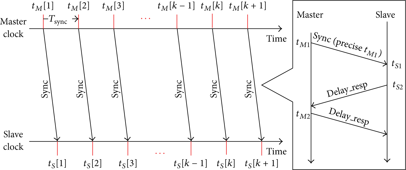
The measurement of the offset and propagation delay is based on the DC mechanism in EtherCAT. In DC-enabled devices, the slaves are provided with an internal clock, namely, the local time, and a mechanism is foreseen that makes a global clock called system time. Every slave is provided with a local copy of the system time that is synchronized with the reference time which coincides with the system time of reference clock. The measurement principle is shown in Figure 1.
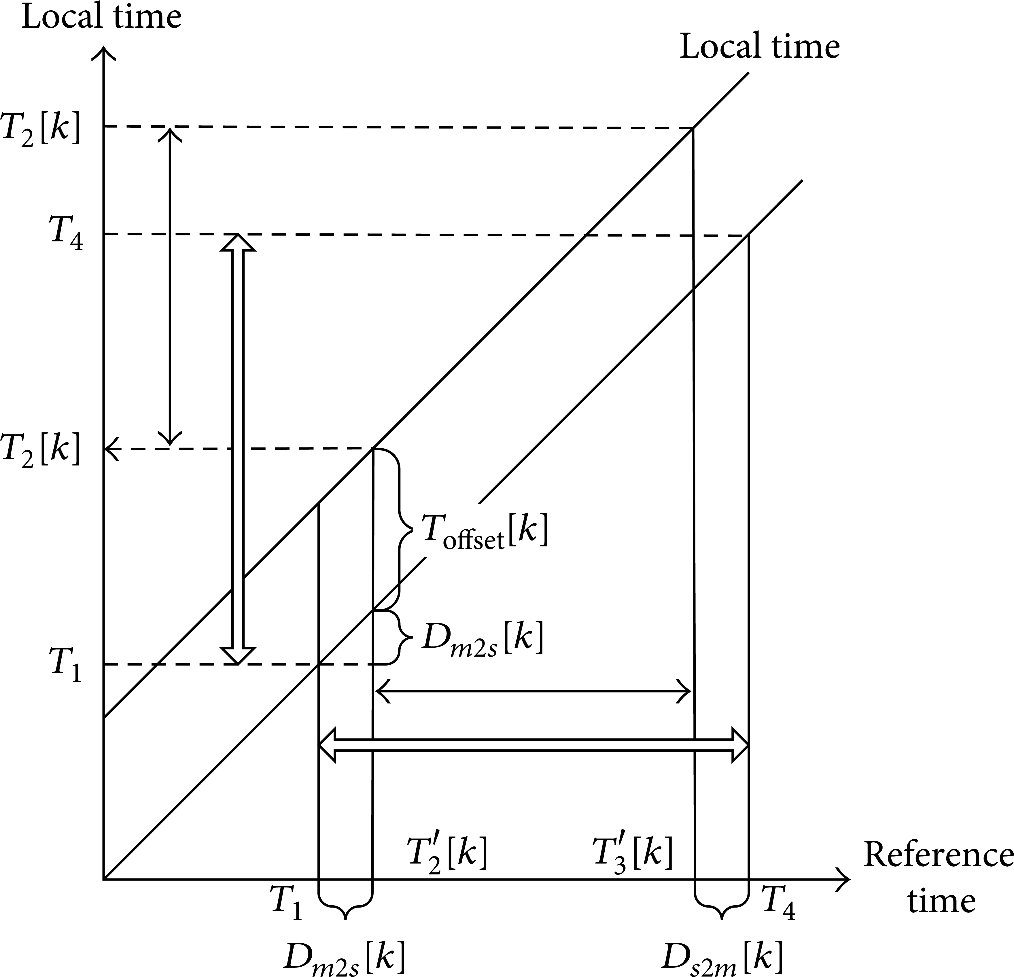
Propagation delay and offset compensation measurement schematics.
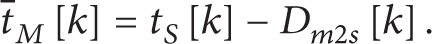
The abscissa represents the reference clock (the master node clock, reference time), denoted as t M [k], and the ordinate represents local time of a slave node, denoted as t S [k], where k is the kth time for the master node sending messages. The offset compensation for the kth measurement is Toffset[k], and the propagation delay for the kth measurement is described as Dm2s[k] (from master to slave) and Ds2m[k] (from slave to master). In this paper we assume that Dm2s[k] is equal to Ds2m[k]. Assuming that t S [k] ≥ t M [k], then their relationship is determined by the following formula:

The steps to measure and calculate propagation delay and initial offset for the kth time are as follows. For the kth time, the master sends a broadcast write command to transmit the data frame, after the data frame reached each slave node, and then the slave node saves its port SOF with the frame arriving time. From Figure 1, for the certain slave node, first, tM1[k] is presented as the time T1 when master node sends messages to slaves, tM1[k] = T1, and tS1[k] is shown as the time T2[k] when the slave node n received the message, tS1[k] = T2[k]. Then we have the following equation:

Because the network is a ring network, the frame will be sent back to the slave nodes and then the master node. When the frame is sent back to the slave node again, we denote the time as tS2[k] such that tS2[k] = T3[k] and when the frame is arrived at the master node we denote the time as tM2[k] such that tM2[k] = T4. Assuming a uniform cable delay and the processing time and forwarding time in all slaves are the same, Dm2s[k] can be calculated by the following equation according to the geometry of Figure 1:


From (4), Toffset[k] can be also calculated. In fact, Toffset[k] and Dm2s[k] are a substantially constant in the operation process, so they can be measured only at the first time.
2.2. EtherCAT Frequency Compensation Algorithm
The above measurement is only a coarse synchronization process. In fact, due to the characteristics of the crystal, with the growth of time, the frequency of the crystal itself will be inconsistent with the nominal frequency and it will cause a linear error. In order to eliminate this error, EtherCAT uses the TCL (time control loop) technology. The concept of TCL is shown in Figure 2.
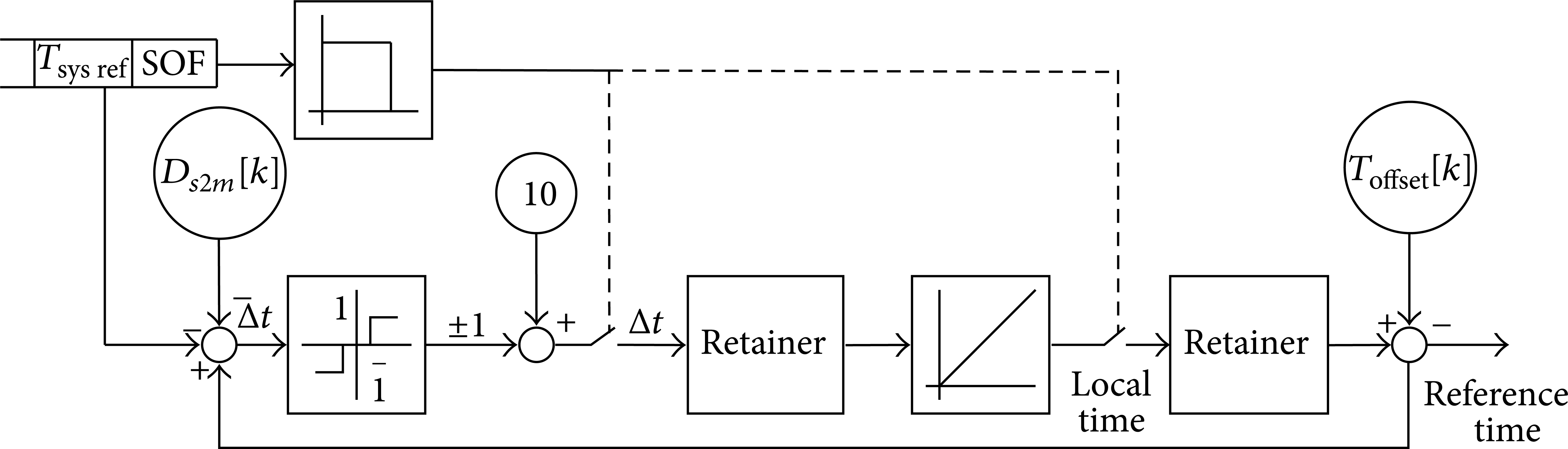
Principle of EtherCAT frequency compensation algorithm.
Through this TCL, the slave can evaluate the reference time as
If
According to the above analysis, the EtherCAT frequency compensation algorithm can be modeled as shown in Figure 3.
Compensation model of EtherCAT.
In Figure 3, D(z) can be shown as a relay model:

2.3. Optimal PI Clock Compensation Algorithm
This paper imposes a clock synchronization algorithm called optimal PI clock servo (PICS), which is a PI clock compensation algorithm based on IEEE 1588 precise time protocol (PTP). This controller can adjust the compensation value automatically as the error value changes; then, the problems of the EtherCAT synchronization algorithm will be solved. First, it is the modeling of master clock and slave clocks.
2.3.1. Clock Model of Frequency Compensation
The clock model of main joint is a p-bit clock counter as shown in Figure 4. The clock of the main joint is the unique reference clock in the entire network. The clock signal is multiplied after the local crystal oscillator dealt with PLL to get a higher clock resolution precision.

Clock model of the master node.
To achieve high-precise clock synchronization, all the slave joints are required to adjust frequency online to get the same frequency with the master clock. Slave joints use the clock model [16] as shown in Figure 5.

Clock model of the slave nodes.
The clock model is composed of a frequency compensating circuit, including a p-bit clock counter, a q-bit accumulator, and an r-bit addend register. The addend register is used to latch frequency compensating value computed by clock synchronization algorithm. The accumulator is connected with the addend register to accumulate the frequency compensating value and to create a carry flag. The clock counter is connected with accumulator to implement the output of local system time. When the accumulator creates a carry flag, the clock counter adds a clock period value to system time. When the module is triggered, the accumulator adds its value with value stored in addend register, and the result will be stored in the accumulator at the same time a carry flag will be created to present whether the addition overflows. If there is an overflow, the system clock will add a clock period value. Unit-time clock counter value is increased. The counter adding times in unit interval are determined by the value of addend register and crystal frequency. As the addend value in addend register is changed, the times of overflow caused by addition and the adding frequency of clock counter will change; as a result, the crystal frequency compensation is realized.
The mathematical modeling for the clock model of slave nodes as shown in Figure 5 is conducted. In the model, y[k] is the output which is the local time and u[k] is the input which is the value of frequency compensation. The clock model can be described as z transfer function:

where Tsync is the clock synchronization cycle and k c is the clock constant. Assume the nominal clock frequency of the master and slaves is f0; then the value of k c is k c = f0/u[0]. The value of frequency compensation u[0] is determined by the values q and r and the PLL configuration in the frequency compensation circuits. Assume the frequency created by slaves internal crystal oscillator is fPLL. Record that Ratio = fPLL/f0 and frequency compensation value is CompPrecision, such as 1 × 10⁻⁹; then the following equations are u[0] = 2 q /Ratio, CompPrecision ≤ 1/(Tsync × f0), 2 q ≥ Ratio/CompPrecision, 2 r ≥ 2 q /Ratio, and 2 p ≥ 2 q .
Figure 6 is the diagram of precise time synchronization process.
Model of precise time synchronization process.
In Figure 6, the master node sends the synchronization message, Sync, in cycles, where Tsync is the clock synchronization cycle, k is the kth clock synchronization process, t
M
[k] presents the master system time when the master node sends the kth synchronization message, and t
S
[k] is the slave local time when the slave receives the kth synchronization message. For example, t
M
[1] is the master system time when the master node sends the first synchronization message and so on. According to the precise clock synchronization protocol, at each period measuring the offset, the unidirectional transmission delay Dm2s[k] will be updated, so the slave node can evaluate
2.3.2. Control Mode of Optimal PI Clock Synchronization Algorithm
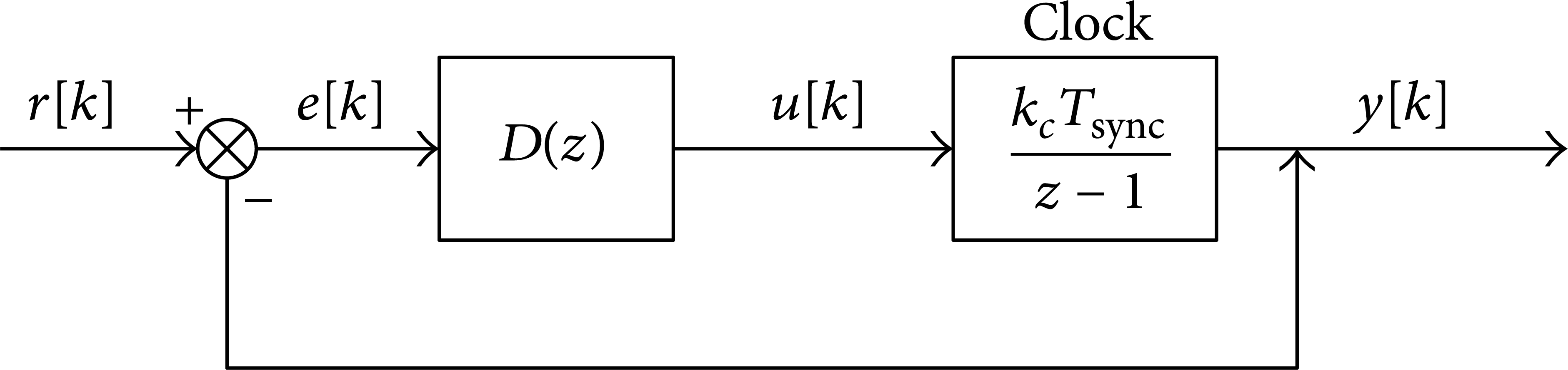
Clock synchronization algorithm is an important component of the precision clock synchronization, and its purpose is to minimize the offset between the master and slaves by adjusting the frequency of slave clock. Currently, literatures [13, 14] have imposed a simple PI controller to realize the clock synchronization to ensure clock skew which is not steady. The algorithm introduces the method of closed-loop control. It uses the online measurement to calculate the delays between slaves and master based on (3) and (4) and a PI controller is imposed to compensate for the slave crystal frequency online to realize the high clock synchronization precision. The control block diagram is shown in Figure 7.

Control model of PI clock synchronization.
While the input signal r[k] is

Combining the model presented as (7) with (8), the closed-loop transfer function of the whole clock synchronization system is described as
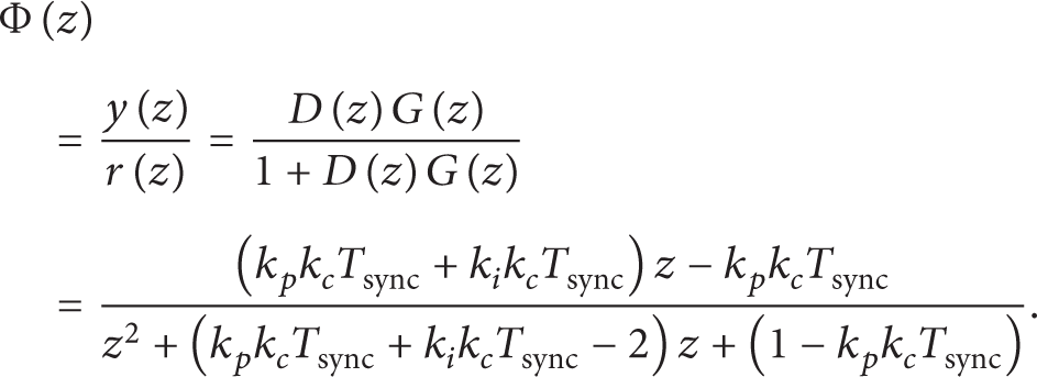
Set P = k p k c Tsync and I = k i k c Tsync; the transfer function Φ(z) can be changed as

Conclusion 1 Stability condition of PICS algorithm can be presented as
The specific derivation process is explained in [17].
Conclusion 2 When optimized parameter is chosen as integrated square error (ISE), P = I = 1 is the optimal PI controller of the PICS algorithm.
In [18], discrete performance of the ISE performance index is described as

Assume r[k] = kTsync; then

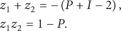
By deforming, the equation can be changed as
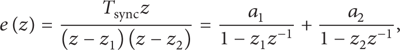
where z1 and z2 are the characteristic roots and a1 = − Tsync/(z2 − z1), a2 = Tsync/(z2 − z1).
To ensure system stability, we can conclude the constraint condition as |z1| ≤ 1, |z2| ≤ 1. The ISE performance index is described as

The derivation process of the equation is omitted here. The following equations hold relationships between roots and the corresponding coefficients:

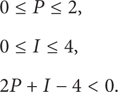
The design problem of PICS algorithm can then be formulated as an optimization problem:

According to the protocol, the Tsync is 1 s in this paper. The solution of the problem must satisfy
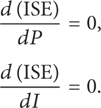
The analytical solution (P,I) is (2, 0), (0, 0), (0, 4), and (1, 1), where (1, 1) is the unique solution.
3. Simulation and Verification
3.1. Simulation Platform
The simulation platform uses the TrueTime toolbox which is a software package developed by Anton Cervin from the Swedish Lund Institute of Technology. TrueTime toolbox can be easily combined with other control modules of Matlab/Simulink software packages and can easily and readily set up network control systems. TrueTime toolbox supplies several modules, including TrueTime Kernel, TrueTime Network, TrueTime Standalone Network, TrueTime Wireless Network, TrueTime Battery, and TrueTime Ultrasound Network. TrueTime Network can be used to simulate the physical layer and data link layer of the network by choosing the CSMA/CD as the network type. The real-time scheduling algorithm of EtherCAT can be programmed in the TrueTime Kernel. The key aspects of algorithm are the frame structure and real-time scheduling timing. The former can be easily achieved by the corresponding struct which is a kind of data structure. The latter can be completed by creating time-driven and event-driven tasks and setting the value of the exectime to simulate running time of tasks. The sending process can be completed by calling the library function ttSendMsg. Finally, the clock synchronization algorithms of EtherCAT and the improved solution can be verified by setting the corresponding parameters of the TrueTime Kernel, including the values of offset and clock drift. The simulation uses TrueTime platform, as shown in Figure 8, to simulate the EtherCAT ring network architecture and build a master node and two slave nodes.

Simulation platform based on TrueTime.
3.2. Experiments Analysis
The two slave nodes are provided with clock drift; the drift of slave 1 is 1.3 and the drift of slave 2 is 0.1. Figure 9 shows that when the frequency compensation algorithm is not used in the two nodes, the error between the master clock and slave clock changes with time and a linear increase with time can be clearly seen.

Variation of error without frequency compensation.
Figure 10 shows, when the EtherCAT compensation algorithm is imposed, how the error changes with the time increasing. In order to eliminate linear growth phenomenon of error, this algorithm sets the stationary compensation value; that is to say, when the error is greater than 0, then the compensation value is 0.1, and when it is less than 0, the value is −0.1.

Variation of error with frequency compensation algorithm of EtherCAT.
In Figure 10, we can notice that the algorithm can protect the error value within a certain range, but its shortcoming is also very obvious. Its error fluctuates all the time and cannot converge. At the same time, the peak of each slave node is very different from each other because of its different drift value. Drift value of slave 1 is 1.3 (T = 1) and its peak is about 20. Drift value of slave 2 is 0.1 and then its peak is only about 0.3. It means that if a slave node has very large drift value, then this algorithm will fail. The PI controller frequency compensation algorithm is introduced and setting P = 1 and I = 1.5, the result is as follows.
In Figure 11, this algorithm eliminates the phenomenon that error cannot converge into EtherCAT compensation algorithm and this feature will not change with the drift value.

Variation of error with the PI compensation algorithm when P = 1 and I = 1.5.
In Figure 12, it still uses the PI controller frequency compensation algorithm, but set P = I = 1. Compared with Figure 11, it can be seen that the convergence precision is not changed, but the convergence rate is faster than Figure 11.

Variation of error with the optimal PI clock servo compensation algorithm when P = 1 and I = 1.
Figure 13 shows that when P = 2.5 and I = 1, the system will be divergent at last. The error even reached 8 × 1034. The reason is that when P = 2.5 and I = 1, the controller is not stable, so it makes the system divergent finally.
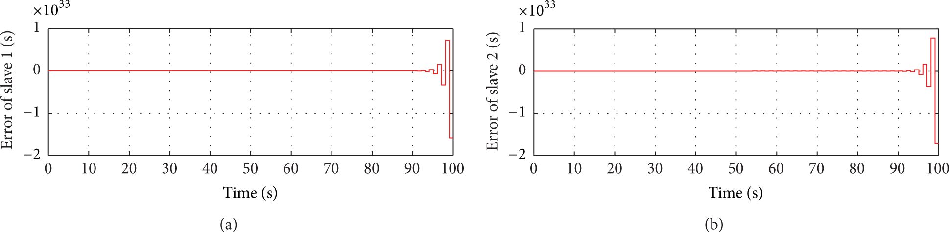
Variation of error with the PI compensation algorithm when P = 2.5 and I = 1.
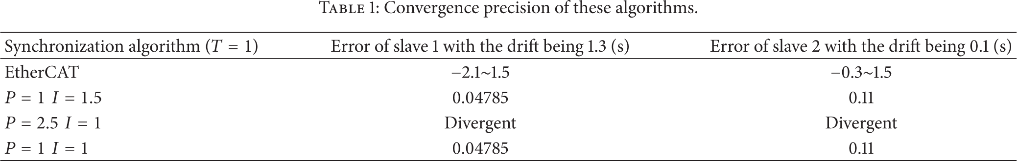
Tables 1 and 2 are the comparison of two different algorithms. One is EtherCAT algorithm and the other is PI algorithm.
Convergence precision of these algorithms.
Convergence rate of these algorithms.

From Table 1, it can be found that all of them cannot converge to zero. The PI algorithm can converge to a constant and the constant value has no relationship with parameters of the algorithm. The reason why PI algorithm cannot converge to zero is that in fact the propagation delay from the master node to the slave node is different from the slave node to the master node. From Table 2, the optimal controller has a fast convergence rate, which is consistent with previous analyses. It can be inferred that PI algorithm's convergence rate is concerned with PI's parameters. If the parameters satisfy the stable conditions, it will converge to a certain value in several steps and the optimal parameter values will contribute to the fast convergence rate. If the parameters of PI compensation algorithm are not satisfied with the stable conditions, the system will be divergent and the algorithm will not be useful.
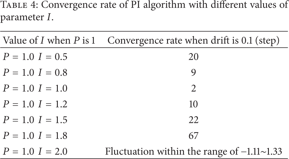
From Table 3 it can be found that when the value of I is set as 1 and the value of P changes from 0.5 to 1.5, it influences the convergence rate. With the value of P increasing, the convergence rate speeds up. But if the value of P is too high, the oscillation numbers of the system will increase. From Table 4 it shows that, with the value of I changing from 0.5 to 2.0, the convergence rate speeds up to only 2 steps at the optimal conditions and then slows down. From the two tables the value of P affects the system more than the value of I.
Convergence rate of PI algorithm with different values of parameter P.

Convergence rate of PI algorithm with different values of parameter I.
4. Conclusions
As the research of Ethernet in automation field goes, the clock synchronization problem in multiaxis motion control system becomes more and more important. This paper presents a new frequency compensation algorithm called PI clock servo. The frequency compensation problem is modeled as a control problem and the control theory approach is imposed to design a PI controller. This paper also presents the stability conditions and the optimal design method under the performance index ISE. At last, a designed TrueTime platform is used to verify the PI algorithm. The experiment shows that the PI algorithm can make the error converge to a near-zero value and when using the optimal PI controller, it can also speed the convergence rate, which verifies the feasibility of the algorithm. In the future work, there are two aspects needed to continue to study. One is about the PI controller and the next work is to improve the controller by adding filter to eliminate the effects due to the unequal round-trip propagation delay. The other goal is to transplant this algorithm in the actual hardware platform in order to get more realistic system parameters.
Conflict of Interests
The authors declare that there is no conflict of interests regarding the publication of this paper.
Footnotes
Acknowledgment
This work was supported by the National Nature Science Foundation of China no. 51275018.