
Abstract
To explore the effect of virtual mass force, the unsteady two-phase flow in a multiphase rotodynamic pump impeller was numerically simulated, where the inlet gas void fraction was 4.9%, 14.9%, and 25.2%, respectively. The drag force and the virtual mass force were accounted for and the cases with and without the latter one were both analyzed for comparison. The results show that the trajectories of the gas bubbles are influenced by the virtual mass force evidently in the inlet extended region. Due to the effect of virtual mass force, some gas will firstly move to the shroud before accumulating in the hub region of the impeller. The characteristic of the pump head was discussed and the results demonstrate that the virtual mass force can decrease the pump head and lead to its fluctuation. In addition, the comparison between the steady and unsteady simulation shows that the virtual mass effect can be found only by unsteady simulation.
1. Introduction
Virtual mass force is one of the general drag forces which includes the drag force, the virtual mass force, and the Basset force [1]. In gas-liquid two-phase flow, as the density of gas is much smaller than that of liquid, the virtual mass force is of prime importance for the motion of the gas bubbles and cannot be neglected. By taking into account the virtual mass force, the reliability of a numerical model may be enhanced. For example, by introducing the virtual mass force term in a three-fluid model for the annular flow inside condensing steam pipes, Hamid and Nemat improved the pressure drop predictions [2]. From the point of numerical simulation, the virtual mass term retained in the momentum equations helps to improve the numerical stability of the initial value problems, extending the parameter range in which the equation system yields real eigenvalues [3].
For gas-liquid multiphase rotodynamic pump, one of the main challenges is that there will exist the phenomena of gas blockage and systematical instability in high gas content mixed transport. To solve this problem, both numerical and experimental studies [4–7] are done to understand the mechanism of phase separation so as to improve the hydraulic and structure design. Through these studies, it has been known on the whole that the difference of centrifugal forces acting on the gas-liquid two phases is the key factor that leads to the separation [7]. However, the detailed mechanism of separation and the characteristics of the mixed transport process, which are closely connected with the gas-liquid interfacial forces, are still not fully clear. In addition, some unknown phenomena may also occur in the gas-liquid mixed transport process. For example, in the study of sound wave propagation in two-phase flow, it is found that the virtual mass terms can cause nonphysical dispersion [3]. To investigate the effect of virtual mass force on the mixed transport process in a multiphase rotodynamic pump, unsteady simulation based on two-fluid model is carried out in this paper. In the simulation, the models both taking and not taking the virtual mass force into account are used to illustrate the difference, and the main attention will be paid on the unsteady two-phase flow process and the energy characteristics of the multiphase pump.
2. Numerical Methods
2.1. Governing Equations
In this work, water and air are taken as the continuous phase and dispersed phase, respectively. The two-phase flow in the rotodynamic pump is postulated as bubbly flow, where the length scale of the gas-liquid interface is smaller or equivalent to the grid size and only the averaged effects of physical variables are concerned. For such flow, the two-fluid model with the Euler-Euler approach is usually applied. Here, both phases are treated as a continuum and they share this domain and interpenetrate as they move within it. The Eulerian modeling framework is based on the ensemble-averaged mass and momentum transport equations for the two phases. The transport equations without mass transfer can be written as follows.
Continuity equation

Momentum transfer equations

where
and subscript k denotes the gas (k = g) or liquid phase (k = l). The terms on the right hand side of (2) are, respectively, representing the viscous stress, the pressure gradient, the momentum exchange between the phases due to interfacial forces, and the mass forces relevant to the rotation of the impeller, which include the centrifugal force and the Coriolis force. The pressure is shared by both the phases.
The turbulent eddy viscosity is formulated based on the SST-k-ω model. This model uses Wilcox model, that is, the original k-ω model at the walls and k-ε model away from walls and solves the problem with the free stream turbulence in the latter part. The use of a k-ω formulation in the inner parts of the boundary layer makes the model directly usable all the way down to the wall through the viscous sublayer. When the SST-k-ω switches to the k-ε model in the free stream, it avoids the common k-ω problem that the model is too sensitive to the inlet free stream turbulence properties [8]. Moreover, a blending factor ensures a smooth transition between the two models. It is generally believed that the SST-k-ω results in relatively good solutions for the flow with a large area of separation. Under this model, the turbulent viscosity is computed as follows:
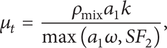
where the mixed density ρmix is given by

2.2. Interfacial Forces
The total interfacial force acting between the two phases may arise from many independent physical effects. However, for the fully developed bubbly flow, the main terms are the drag force and the virtual mass force. The interface momentum transfer due to drag force is given by

where D
b
is the diameter of gas bubbles;

where CD1 and CD2 are the drag coefficients for the viscous regime and the distorted regime, respectively, and are expressed as follows:

where Re b is a modified bubble Reynolds number given by

The virtual mass, also known as added mass or apparent mass, is associated with the force required to accelerate the fluid surrounding a moving body of different phase. It has the effect of liquid retarding, interpreted as inertia force acting on the accelerating bubble. In case of a bubble accelerating in a continuous liquid phase, this force can be described by the following expression [10]:

where CVM is the virtual mass coefficient, which for spherical gas bubbles is equal to 0.5;

According to the above equation, virtual mass force can be divided into two parts: the time-dependent term associated with the difference of local acceleration between the two phases and the space-dependent term associated with the difference of convective acceleration.
2.3. Computational Mesh and Setting
Figure 1 shows the geometry of the impeller and the 3D mesh employed in the flow analysis. Here, only the flow in a single flow passage is simulated by assuming that the flow in the impeller is axisymmetric. To set the boundary conditions reasonably, the inlet and outlet of the passage are extended along the axial direction. To avoid the gas-liquid separation more effectively, the wrap angle of the blade is designed to be much larger (approximately 220° for this pump), and the passage is much narrower in the radial direction than the usual ones. However, such design also makes the generation of high quality mesh much more difficult. To solve this problem, the hybrid mesh is used; that is, the structured mesh is adopted for the inlet and outlet extended region, while the unstructured mesh is adopted for the impeller region. Table 1 lists the details of the mesh, which is generated through the software ICEM_CFD 12.1.
Parameters of the hybrid mesh for flow analysis.


Impeller geometry and the hybrid mesh for flow analysis.
The boundary conditions are set as follows: at the inlet, the axial velocity is specified according to the flow rate, and, at the outlet, an averaged static pressure is given; at the wall boundaries (the pressure and suction surfaces and the hub and shroud walls), the nonslip condition of viscous fluid is used for both phases; for the three pairs of circumferential boundaries, the rotational periodic condition is imposed.
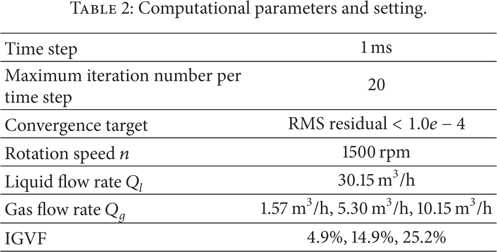
To observe the transport process of gas from the inlet to the outlet, the single water phase flow is firstly simulated in steady mode, and then this solution is specified as the initial field for the transient simulation of the two-phase flow in the rotodynamic pump. All these simulations are carried out through the software ANSYS_CFX 12.1, and the parameters and setting in the simulations are summarized in Table 2.
Computational parameters and setting.
3. Results and Discussion
3.1. Analysis of the Mixed Transport Process
To illustrate the effect of virtual mass force on the gas-liquid two-phase flow in the multiphase pump, simulations by two-fluid models with and without taking the virtual mass force into account are carried out for comparison.
Figures 2–4 are the contour distributions of gas void fraction in the meridional surface as well as their temporal evolution in different IGVF conditions. Due to the rotation of the impeller, as has been analysed in [7], the liquid phase (water) with larger density will suffer larger centrifugal force and thus mainly lies in the outer part of the passage, while the gas phase (air) is expelled by the liquid and most of it will gather near the hub with smaller diameter. Both models (with and without virtual mass force) can give a reasonable simulation about this, as shown in Figures 2–4. However, in the results from the model with virtual mass force, we can see that some of the gas will quickly accumulate to the shroud after it passes the domain inlet, while the results from the model without virtual mass force show that the distribution of gas void fraction in the inlet extended region is relatively even. Obviously, this difference is credited to the virtual mass force. According to the particle transport theory [11], the implemented rotation term also contains contributions from the virtual mass force, and the acceleration arising by rotation force can be written as

Here, ε is the ratio of the original particle mass to the effective particle mass (due to the virtual mass term correction) and ε = ρ
g
/(ρ
g
+ CVMρ
l
); Ω is the rotational frequency and

Contour distribution of gas void fraction and its temporal evolution from model with and without virtual mass force (IGVF = 4.9%).

Contour distribution of gas void fraction and its temporal evolution from model with and without virtual mass force (IGVF = 14.9%).

Contour distribution of gas void fraction and its temporal evolution from model with and without virtual mass force (IGVF = 25.2%).
Another difference between the results of the two models lies in the gas-liquid interface. In the outlet extended region, the phase interface from the model with virtual mass force presents persistent fluctuation, while the interface from the model without virtual mass force is relatively smooth. Figure 5 is an example for this phenomenon, which shows the contour line of α g = 0.2 in the moment of t = 0.28 s in Figure 3. As the two phases both of which are in axial motion have different densities and probably different velocity across the interface, Kelvin-Helmholtz instability [12] may occur; thus the gas-liquid interface may probably be unstable. Therefore, by introducing the virtual mass force, the actual flow phenomenon can be captured with details.

Contour line of α g = 0.2 when t = 0.28 s and IGVF = 14.9%.
3.2. Comparison between the Steady and Unsteady Simulation
The contour distribution of gas void fraction shown in Figure 6 is attained from the steady simulation when IGVF is 14.9% and virtual mass force is considered, where we cannot see the virtual mass effect found in the unsteady simulation shown in the left of Figure 2–4. Figure 7 compares the normalized vectors of virtual mass force from the unsteady and steady cases in the inlet extended region. According to the definition of virtual mass force, the direction of it acting on the bubbles should be reversed from the relative acceleration of gas bubbles to the liquid. Therefore, we can judge from Figure 7 that, in unsteady simulation, the bubbles in the shroud region have a trend of moving outward from the impeller centre, while, in the steady simulation, the bubbles there tend to move towards the centre.

Contour distribution of gas void fraction in steady simulation with virtual mass force (IGVF = 14.9%).

Normalized vectors of virtual mass force in the inlet extended region (IGVF = 14.9%).
Figure 8 shows the magnitude ratio of the virtual mass force (denoted by ξ) in the inlet extended region between the two simulation modes. It can be seen that the magnitude of virtual mass force in the unsteady simulation is much larger than that in steady simulation. This illustrates that the local relative acceleration, that is, the first term in the right hand side of (11), can play an important role in the gas-liquid mixed transport process.

Magnitude ratio of virtual mass force between the unsteady simulation (IGVF = 14.9% and t = 0.28 s) and steady simulation in the inlet extended region.
3.3. Virtual Mass Effect on Head Performance Prediction
In gas-liquid two-phase flow, the gas fraction must be taken into account for the calculation of external characteristics of a pump [13]. If we denote x as the mass flow rate ratio of gas to the two-phase mixture, the head of the pump operating under gas-liquid two-phase flow condition can be obtained by

The heads for the gas and liquid phases H g and H l are expressed as

Figure 9 shows the temporal evolution of the pump head in three IGVF conditions. It can be seen that the inclusion of virtual mass force makes the predicted head of the two-phase pump fluctuate with time, while the head curves from the model without this force are rather smooth. This can be easily understood from the distribution of gas void fraction in Figures 2–4. Due to the fluctuation of gas void fraction at the outlet, the outlet parameters such as p d and c d in (14) will correspondingly fluctuate, thus leading to the fluctuation of the pump head. In fact, this phenomenon has been observed through the experiment. Therefore, the inclusion of virtual mass force in the numerical model makes the simulation more reasonable.

Temporal evolution of the head of the multiphase rotodynamic pump.
As shown in Figures 2–4, before the moment t = 0.20 s, the gas in the three IGVF conditions has not arrived at the outlet, so the initial time range (0–0.20 s) should be cut off so as to compare the predicted head with the experimental one. Table 3 makes such a comparison, where the head values from the models with and without virtual mass force are the averages between t = 0.20 s and t = 0.30 s. From the table, we can find that the head values from both models are close to the experimental ones, but the values from the model with virtual mass force are all smaller. Obviously, this is because the motion of the fluid media, especially the gas, will suffer more drag by introducing this force; thus the boost of the total pressure will be weakened.
Comparison of the head values between the simulations and the experiment.
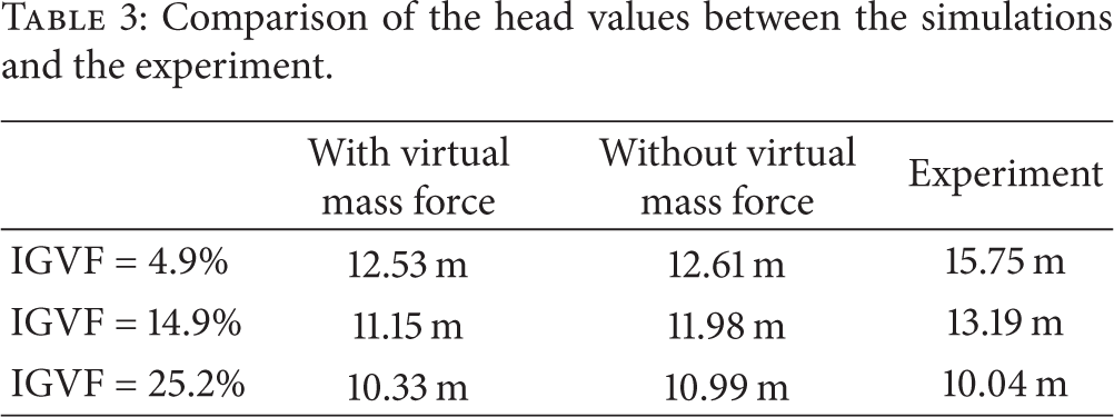
Although, in the cases of IGVF = 4.9% and IGVF = 14.9%, the model without virtual mass force can acquire a closer head value to the experiment, we cannot say that virtual mass force should not be included in the simulation, because the reliability judgment for a numerical model should take into account many factors, including both the external characteristics and internal characteristics. In the next step of our research, the internal flow of the pump will be investigated through the technologies of high speed video.
From Figure 9 and Table 3, it can also be found that the increase of IGVF, which is accompanied by a constant liquid flow rate, will decrease the head of the multiphase pump. This is because the increase of gas flow rate can reduce the cross section area for the liquid; thus the velocities of both phases will increase, which leads to the increase of the head loss.
4. Conclusions
The interfacial forces have important effects on gas-liquid two-phase flow. In this paper, based on the two-fluid models with and without virtual mass force, the gas-liquid two-phase flow in a multiphase rotodynamic pump is simulated so as to analyze the effect of virtual mass force on the mixed transport process in fluid machinery. The results can be summarized as follows.
In the gas-liquid mixed transport process of a multiphase rotodynamic pump, virtual mass force has a reverse effect relative to the centrifugal force, and it will make some gas firstly move to the shroud before accumulating in the hub region of the impeller.
By exerting more drag to the motion of the bubbles, the virtual mass force can decrease the head of a multiphase rotodynamic pump; at the same time, it can lead to the fluctuation of the pump head.
The virtual mass effect can be found only by unsteady simulation, which illustrates that the local relative acceleration is an important factor for the generation of virtual mass effect in the multiphase pump.
Footnotes
Nomenclature
Conflict of Interests
The authors declare that there is no conflict of interests regarding the publication of this paper.
Acknowledgments
This study is supported by the National Natural Science Foundation of China (nos. 51009003 and 51179090) and Open Research Fund Program of State Key Laboratory of Hydroscience and Engineering (sklhse-2013-E-01).