
Abstract
In the subsea pipeline gathering system, severe slugging flow is prone to occur. Severe slugging flow brings major threat to production and flow assurance in oil and gas industry due to periodical pressure oscillation and large liquid volume. Currently many researchers pay much more attention on L-shaped riser, catenaries, and S-shaped riser; little research has been made on hybrid riser, which is applied in the Africa West and Gulf of Mexico oil fields. Flow characteristics simulation for hybrid riser is made in this paper, using the one-dimensional and quasi-equilibrium model to simulate not only the riser-base pressure, severe slugging period, and the liquid slug length of the whole system but also base-pressure in the flexible pipe section. The calculated results match well with the experiment data. Besides, the influence of flexible pipe to the severe slugging characteristics of hybrid riser system is analyzed, which are significant for the determination of riser structure.
1. Introduction
Offshore pipeline has emerged as new forms in Gulf of Mexico, Brazil, and West Africa, where focus on almost all the newly discovered deep-sea exploration wells and reserves in the world.
In multiphase offshore pipelines, because of the terrain topography and the local flow conditions, the liquid phase always accumulates in the low points of the pipeline and forms the severe slugging phenomenon. When severe slugging occurs, there are always the periodic pressure oscillation and large liquid which often bring out the facilities shutdown and damage. There are mainly two kinds of researches on it, one is the flowline-riser slugging originating from 1980s and the other is the terrain-induced slugging. The former has been studied experimentally in several laboratories, mostly with a straight flowline and a vertical riser configuration named L-shaped riser (e.g., [1–3]). Moreover, there are also some experimental researches about the flexible riser (e.g., [4–6]). Experimental studies were conducted with an air-water two-phase flow on three different geometries, which include free-hanging catenary, lazy-S, and sharp-S riser. Terrain-induced slugging has been paid much attention in experimental and model study (e.g., [2, 7, 8]).
Also as for the flow characteristics of flexible riser, S-shaped riser is made by experiment and commercial software, only the flow in centenary riser is modelled by Balino et al. [9].
When L-shaped riser and flexible pipe are applied together, the gas-liquid two-phase flow characteristics simulation is not reported right now. This kind of riser called hybrid riser with good features is suitable for deepwater and ultra-deepwater oil field.
According to Wang et al. [10], L-shaped severe slugging model is not suitable to simulate the severe slugging of hybrid riser.
Based on the previous studies, the experimental analysis of severe slugging flow characteristics in the hybrid riser is made and the model is established to describe the pressure, period, and liquid length both in vertical pipe and in flexible pipe. The influence of flexible pipe geometry change to the severe slugging characteristics is also analyzed.
2. Dynamic Model
The phenomenon of severe slugging in hybrid riser system has been subdivided into four stages; separate mathematical model for each phase is established.
The model basic purpose is to describe the dynamic characteristics of severe slugging occurring in the hybrid riser system, including the pressure and liquid characteristics.
The development of the model is quasi-equilibrium, based on one-dimensional gravity-dominant flow in both the pipeline and the riser.
2.1. Description of the Four Stages of Severe Slugging Phenomenon for the Hybrid Riser
Severe slugging phenomenon is described here to demonstrate the difficulty of the severe slugging simulation for the hybrid riser.
Severe slugging flow begins at the time when the liquid slug flows out from the riser topside and entered the separator [1]. The four stages are shown in Figure 1.
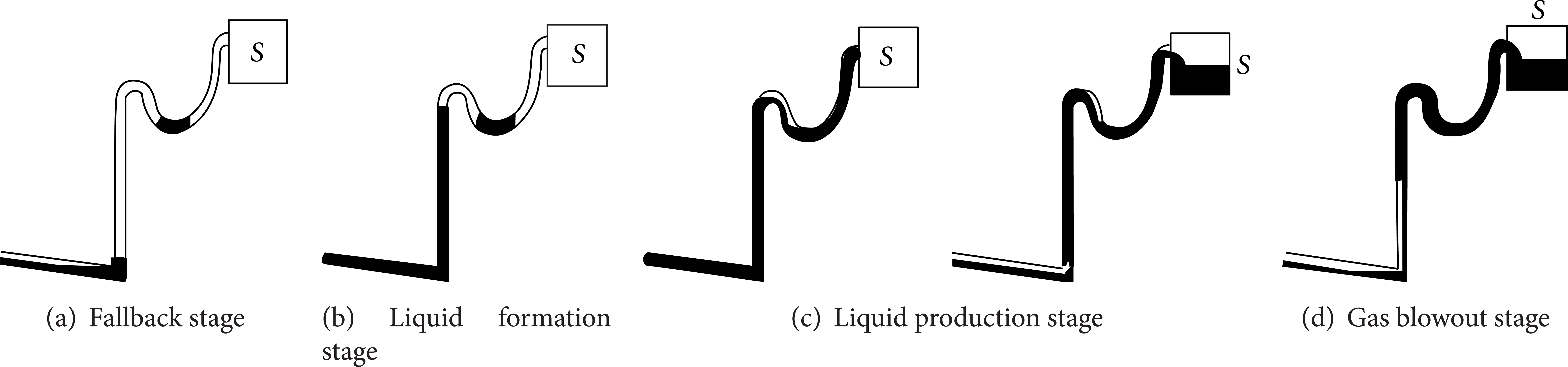
Sketch of four stages for severe slugging of hybrid riser.
(1) Liquid Fallback. Because there is stratified flow in the pipeline, the gas which is followed by the liquid slug begins to expand suddenly, carrying liquid from the riser top into the separator. After the gas blowout stage, the liquid starts to fall down along the riser and finally bridges the liquid entrance into the riser, which is called liquid fallback.
In the flexible pipe, liquid fallback occurs at the same time after the gas blowout.
(2) Slug Formation Stage
First: Liquid Slug Forms in the Perpendicular Pipe. After liquid fallback, the gas into the riser is blocked and the gas pressure in the pipeline increases as the liquid accumulate in it continuously. Since the increase of gas pressure in the pipeline with the time change is less than the hydrostatic pressure increase with the time change in the riser pipe, the liquid will accumulate continuously. When the liquid slug reaches the top of the vertical riser, liquid slug flows into the flexible pipe.
Secondly: Liquid Slug Forms in the Flexible Pipe. The length of the flexible riser is much shorter than the perpendicular pipe; there is stratified flow in the lower limb of the flexible riser, and the liquid begins to accumulate at lower limb and the upper limb of the flexible riser. When the liquid slug reaches the top of the flexible riser, the slug formation stage ends, and the slug-production stage will begin.
(3) Slug-Production Stage. During the slug-production stage, the pressure in the base of the perpendicular riser stays the same and only sometimes decreases slightly as the gas at the lower limb of the flexible riser enters the upper limb of the flexible.
(4) Bubble Penetration Stage. The bubble penetration stage is characterized by an abrupt expanding of gas bubble that exceeds the riser-pipe liquid and leaves a thin film along the riser-pipe wall, which happens both in vertical pipe and in flexible pipe.
This stage keeps on until the bubble enters the separator, when the riser-base pressure is minimal.
Therefore, severe slugging phenomenon for HR is different from the L-shaped riser because of the flexible pipe. It is necessary to develop a new model to simulate the flow characteristics for the HR.
According to the experiment observation, it is concluded that the flexible pipe length and flexible pipe span change will influence the flow characteristics in the HR system.
Figure 2 illustrates the configuration of the hybrid riser and the variables used in the following equations, which is also displayed in Figure 2. The specific values related to the geometry in the experiment are showed in the Appendix. The flexible pipe is simplified to be taken as a segment like showed in Figure 3, which is used by Nydal et al. [11] to tackle the S-shaped riser flow model.

Model diagram for hybrid riser.

Schematic diagram of the flow in flexible pipe.
The mathematical model is established for each stage, and the variable values of the former stage are taken as the initial value of next stage. In this paper, we assume the liquid flow direction is positive.
2.2. The Gas Accumulation Stage in the Inclined Pipeline
Conservation of Mass for the Pipeline Gas. The equation of state (EOS) for the gas phase in the pipeline and in the buffer tank is as follows:

where μ g is the molecule mass of the gas.
The EOS for the flexible inclined pipeline is
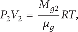
where P, V, and W is the function of time t.
(1) The First Step
The Liquid Accumulation in the Vertical Pipe. The liquid fallback in the flexible pipe is neglected, so the gas pressure in the lower limb of the flexible pipe

The gas pressure P1 in the inclined pipeline is as follows:

The gas volume in the inclined pipeline is

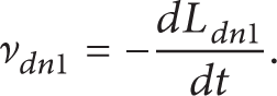
The velocity of liquid slug in the inclined pipe is vdn1, so the height of liquid tail in the inclined pipeline is Ldn1, just as
At present the tail height of the liquid slug in the lower limb of the flexible pipe Lup2 = 0.
The accumulation velocity of the head of the liquid slug in the vertical pipe is

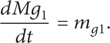
According to the conservation of mass for the gas in the inclined pipeline, we can get the equation
According to the conservation of mass for the liquid slug in the whole system, we can get

Calculation Procedure for Slug Generation in the Vertical Pipe. Equations (1) and (3)–(9) form equation set to solve the variables Lup1, Ldn1.
The Initial Calculation Condition. The beginning of the gas accumulation in the inclined pipeline is the start point of the liquid slug formation stage.
Gas volume in the inclined pipeline is V c + α1AL; the gas mass Mg01 in the inclined pipeline is get by the known variables. The liquid holdup is calculated by empirical relationship called Mukherjee-Brill method.
The End Calculation Condition. The head of the liquid slug arrives in the top of the vertical pipeline Lup1 = Lr1.
(2) The Second Step. The liquid accumulates in the flexible pipe. When severe slugging happens, the liquid accumulation in the flexible pipe is similar to the process in the pipeline-riser system. There is the laminar flow in the lower limb of the flexible pipe and there is pure liquid slug in the upper limb, just as shown in Figure 3.
The gas pressure in the lower limb of the flexible pipe is

At the moment, the gas pressure in the inclined pipeline is

The volume in the inclined pipeline is

The volume in the lower limb of flexible pipe is
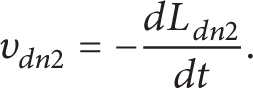
The accumulation velocity of the liquid slug tail in the lower limb of the flexible pipe is
The accumulation velocity of the liquid slug in the inclined pipe is

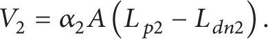
The accumulation velocity of the liquid slug in the upper limb of the flexible pipe is

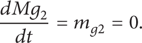
According to the conservation of mass for the flexible pipe, we can get dMg2/dt = mg2 = 0, which mean the mass in the flexible pipe is constant:
According to the conservation of mass for the inclined pipe, we can get
According to the conservation of mass for the liquid in the system, we can get

Calculation Procedure for Slug Generation in the Flexible Pipe. Equations (1), (2), and (10)–(19) form the equation set to solve the variables Ldn2, Ldn1, and Lup2.
The Initial Condition. The initial condition is the condition parameters of last stage.
The End Condition. The liquid head arrives in the top of the flexible pipe; that is, Lup2 = Lr2.
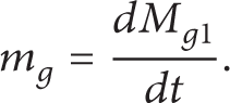
In this stage, the liquid holdup in the lower limb of the flexible pipe is calculated by open channel model. The gas mass in the flexible pipe is got according to the mass conservation, showed as

2.3. Liquid Slug-Production Stage
In the liquid production stage, the liquid flows into the separator, so we can get

Marking the liquid mass flowing out of the riser system as m s , it is found that there is only the liquid level in the inclined pipeline changing, so according to the mass conservation for the liquid, we can get

Calculation Procedure for Slug Production. Equations (1), (5), (6), (21), and (22) form the equation set to solve the variables m s , Ldn1.
The Initial Condition. When the liquid slug flow into the separator, t = t1. The initial variable values for this stage are the last values of the liquid generation stage.
The End Condition. The liquid tail in the inclined pipeline is zero; that is, Ldn1 = 0.
2.4. Bubble Penetration Stage
According to the research of previous experimental and theoretical studies, the main sections of severe slugging period are the first stage and second stage. Eruption phase of severe slugging is very short relative to the generation and production stage. The main difference of severe slugging between the HR and L-shaped riser lies in the slug formation and slug-production stages. So we take the HR as the L-shaped with the equivalent height H = Lr1 + Lr2sinβ − Lp2sinγ. The detailed process is shown in Figure 5, according to Taitel et al. [2] model.
The Initial Condition. The calculation results from liquid slug production.
2.5. Fallback Stage
Once the liquid velocity is less than zero, no liquid enters the riser; the liquid will fall downward the riser. Thus, liquid fallback occurs when v L become negative:

According to the experimental analysis, the liquid fallback of HR is larger than the L-shaped riser. The fallback liquid height is
3. Results and Discussion
3.1. Comparison between Experimental and Simulation Results
Table 1 shows the comparison results between experiment and simulation. Table 2 is the error analysis results. The pressure in the table means gauge pressure. The experiment data are got in the multiphase flow experiment lab at China University of Petroleum, Beijing, as showed in the Appendix.
Comparison of flow characteristics between experimental and model results for HR.

Error between experimental and modelling results.

From the calculation results in Table 3, showed in Figures 4, 5 and 6. It is found that the model simulates the riser-base pressure, period, liquid length, and the base pressure of flexible pipe well; the error is acceptable. So the model should be applied further to research on slug control.
Comparison of flexible pipe pressure between experimental and model results.


Comparison of liquid length between experiment and simulation.

Comparison of period between experiment and simulation.

Comparison of riser-base maximum pressure between experiment and simulation.
4. Analysis on Influence of Flexible Pipe to Severe Slugging Characteristics
4.1. Influence to the Riser-Base Pressure
Under the same total height of the riser, the presence of flexible pipe will bring the following.
(1) Liquid fallback amount in HR is larger than that of L-shaped riser, which makes the pressure in flexible pipe bigger than the separator pressure. However, the liquid fallback in the flexible pipe will cause system oscillation. From the prospective of valve control, it is one of the reasons that severe slugging range is smaller than the L-shaped riser as showed in Figure 7.

Contrast of riser-base pressure of L-shaped riser and HR under the same riser height.
(2) The largest riser-base pressure is more than that of L-shaped riser. Because during the slug-production stage, there is some air in the lower limb of flexible pipe, as shown in Figure 8.

Diagram of slug production stage of severe slugging flow for hybrid riser system.
According to the Bernoulli equation, slug-production stage is taken as quasi-stable state. The riser-base pressure in the L-shaped riser is expressed as

The riser-base pressure in the flexible riser is expressed as
Just as observed in the experiment, when severe slugging happens, there is very thin liquid film in the lower limb of flexible pipe, so the liquid holdup is very small; that is, ρmix≪ρ, so P L < PHR. From the quantitative prospective, analysis is made as shown in Table 4. We can see that the PHR is larger than P L by 15%~20%.
Comparison of riser base pressure between HR and L-shaped riser.

Note that Δ = ((PHR − P L )/P L ) × 100.
PHR: hybrid riser base maximum pressure.
P L : L-shaped riser base maximum pressure.
(3) Severe slugging period of hybrid riser is smaller than that of L-shaped riser. According to the experimental phenomenon, the most important reason is that the liquid fallback amount in hybrid riser is more than that in the L-shaped riser, which will lead to the time reduce of slug-production stage, as shown in Table 5.
Comparison of period for HR and L-shaped riser system.

So, period of hybrid riser is smaller than L-shaped riser by about 12.09%.
4.2. Influence of the Span of Flexible Pipe to Severe Slugging Phenomenon
As for hybrid riser, the span of flexible pipe means the horizontal length between the top of the vertical pipe and the interface of flexible pipe in the FPSO. In the real production system, there is always the span change because of the movement of FPSO.
Just as showed in Figure 9, the comparison of the base pressure is made when the span is 1.2 m and 1.5 m, respectively.
Contrast of riser-base pressure of different flexible span.
As for hybrid riser, the change of span has little influence on the pressure characteristics.
4.3. Influence of the Length of Flexible Pipe to Severe Slugging Characteristics
Just as shown in Figure 10, the comparison of the base pressure is made when the length of flexible pipe is 2.2 m and 3 m, respectively.

Contrast of riser-base pressure of different flexible lengths.
Figure 10 shows that the period will increase as the length of flexible pipe rises, which is caused by the time increase of slug accumulation. Besides, the biggest riser-base pressure increases, which is caused by the gas increase in the lower limb of flexible pipe.
Moreover, the largest base pressure decreases at the stage of liquid production when both gas and liquid velocities are large, which is because the gas in the lower limb of flexible pipe will enter the upper limb and separator gradually.
The analysis of the influence of flexible pipe to the severe slugging is beneficial and vital to choose the appropriate riser structure in the real production of deepwater oilfield.
5. Conclusions
Hybrid riser is suitable for deepwater petroleum production. However, little research has been made. Here a one-dimensional and quasi-equilibrium model is established to simulate the pressure, period, and liquid length, which takes into account the four stages of severe slugging flow. The simulation result trend line matches experiment results well. And it could be further developed and amended to go on the slug control research, because of the good simulation of riser-base pressure, and liquid length simulation could be the reference for the slug-catcher design and the period prediction result can be used to go on fluid-solid coupling research.
This model is only suitable for the classic severe slugging phenomenon, as for the transition severe slugging and other unstable flow; further theoretical study is necessary and significant for the riser structure determination and flow assurance operation.
The hybrid riser experiment is performed well to analyze the influence of flexible pipe to severe slugging characteristics and validate the theoretical model. The flexible pipe will make the maximum riser-base pressure in HR increase by 15–20% than that in L-shaped riser; the period average decreases by 12.09%. The change of flexible pipe span has little influence on the pressure characteristics. The period and maximum riser-base pressure will increase as the length of flexible pipe increases. When both gas and liquid velocities are large enough, the gas in the lower limb of flexible pipe will enter the upper limb and separator at last, which will lead the largest base pressure to decrease at the stage of liquid production.
Footnotes
Appendix
Nomenclature
Conflict of Interests
The authors declare that there is no conflict of interests regarding the publication of this paper.
Acknowledgments
The authors wish to thank the CNOOC in China for the research funds of China University of Petroleum, Beijing for providing support for this work, and the authors wish to thank China Scholarship Council for the sponsor of my study in Cranfield University (foundation items: National Science & Technology Major Project “Deepwater Flow Assurance Design and Flow Management Technology,” Project no. 2011ZX05026-004-003).