
Abstract
A new hierarchical control strategy for active hydropneumatic suspension systems is proposed. This strategy considers the dynamic characteristics of the actuator. The top hierarchy controller uses a combined control scheme: a genetic algorithm- (GA-) based self-tuning proportional-integral-derivative controller and a fuzzy logic controller. For practical implementations of the proposed control scheme, a GA-based self-learning process is initiated only when the defined performance index of vehicle dynamics exceeds a certain debounce time threshold. The designed control algorithm is implemented on a virtual prototype and cosimulations are performed with different road disturbance inputs. Cosimulation results show that the active hydropneumatic suspension system designed in this study significantly improves riding comfort characteristics of vehicles. The robustness and adaptability of the proposed controller are also examined when the control system is subjected to extremely rough road conditions.
1. Introduction
Suspension systems are essential to determine vehicle comfort and safety performance, particularly for heavy-duty military vehicles. The suspensions of such vehicles are expected to be appropriately designed to provide good manoeuvrability over rough terrain surfaces, thus allowing them to achieve high travelling speeds. The special requirements of these types of vehicles have attracted increasing attention on hydropneumatic suspension from both research and practical perspectives; this suspension type exhibits superior vibration-attenuation capability that covers the resonant frequencies of the main vehicle body (e.g., pitch and roll) whilst satisfying the requirements of attitude adaptation and steering control of the vehicle body [1]. Performance requirements of advanced vehicle suspensions are always in conflict. Enhancing comfort in vehicles results in large suspension strokes and small damping in the wheel-hop mode, whereas excessive suspension bottoming leads to a considerable decline in riding comfort and possible structural damage [2, 3]. Several active suspension control approaches based on various control techniques have been proposed to manage the trade-off among conflicting performance requirements [2–10].
Developing active hydropneumatic suspensions to improve vehicle riding comfort and handling performance is complicated because such systems incorporate mechanical, electrical, and hydraulic systems that are controlled via electronic systems with integrated software. These systems are expected to operate over a wide range of road conditions and some of the tests required to validate them are possibly dangerous or impractical [1, 11]. Fundamental changes in the traditional development process result from the requirement for sophisticated vehicle functionality with high performance and reliability levels whilst reducing development time. This study applies an efficient development approach based on virtual prototyping and cosimulation technologies that simulates a field test environment under a controllable situation. This approach can provide consistent and reproducible tests that enable solving safety critical issues during the early stages of product development and prior to on-vehicle testing. Therefore, a complicated mechatronic system with a high degree of maturity can be developed within a short period by using the proposed development approach. Moreover, the developed virtual prototypes are useful for extensive parameter studies and optimisations, which provide further insight into complex nonlinear interactions of chassis systems. This study proposes a new hierarchical control strategy for active hydropneumatic suspension systems; the strategy considers unpredictable road excitation and strong nonlinearities associated with vehicle dynamic model and suspension actuators [12]. The top hierarchy controller uses a combined control scheme, that is, a combination of a genetic algorithm- (GA-) based self-tuning proportional-integral-derivative PID controller and a fuzzy logic controller. The GA-based self-tuning PID controller minimises vertical acceleration of a vehicle body, whereas the fuzzy logic controller minimises pitch acceleration whilst attenuating vertical acceleration of a vehicle body by tuning weighting factors. The bottom hierarchy controller, which is derived from the nonlinear model of a hydropneumatic spring and actuator, is used to control the proportional and directional solenoid valves according to the desired control forces of the top hierarchy controller. For practical implementations of the proposed control scheme, a GA-based self-learning process is only initiated when the defined performance index of vehicle dynamics exceeds a certain debounce time threshold. The effectiveness of the proposed GA-based hierarchical control strategy is validated through an active suspension digital development platform, which is established by using virtual prototyping and cosimulation technologies.
2. Full Vehicle Active Suspension Model
A full vehicle active suspension model is proposed and shown in Figure 1. This model consists of a vehicle body mass M b and four wheel masses m ti , where i ∈ [1,2, 3,4]. Vehicle body mass is a rigid body that exhibits freedom of motion in vertical, pitch, and roll directions. The vertical displacements at each suspension point are denoted by z1, z2, z3, and z4. The displacement at the centre of gravity (C.G.) of the vehicle, pitch angle, and roll angle are denoted by z b , θ, and φ, respectively. The vertical displacements of unsprung masses are denoted by zt1, zt2, zt3, and zt4. The moments of inertia around the x- and y-axes are denoted by I x and I y , respectively. The respective distances from the front and rear axles to the C.G. of the vehicle body are denoted by lengths a and b. In the model, road roughness causes disturbances zr1, zr2, zr3, and zr4. The motion equations for the vehicle body and the front and rear wheels are given as

where

Vehicle dynamics model with active hydropneumatic suspensions.
Assuming that the pitch and roll angles of a vehicle body are sufficiently small, the relationship between the vertical vibration acceleration of each suspension and vehicle body joint points
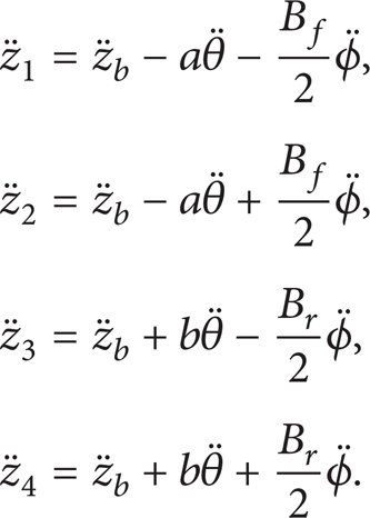
The vibration acceleration at the centre of the front and rear axles can be expressed as follows:


3. Control Strategy
The control strategy comprises two hierarchical components. They are designated as the top and bottom hierarchy controllers in this study.
3.1. Top Hierarchy Controller
The top hierarchy controller uses a combined control scheme, that is, a combination of a GA-based self-tuning PID controller and a fuzzy logic controller. The self-tuning PID controller minimises vertical acceleration of the vehicle body, whereas the fuzzy logic controller minimises pitch acceleration as it further attenuates vertical acceleration of the vehicle body by tuning the weighting factors. By considering the limited response frequency of the executing mechanism, a second-order low-pass filter is applied to reject high-frequency force signals. The GA is used to obtain the optimal feasible parameter region for the top hierarchy controller. The proposed scheme is expressed as the sum of the PID and fuzzy controllers as follows:

where the subscripts i ∈ [1,2, 3,4] represent the front left, front right, rear left, and rear right controllers, respectively, uPIDf and uPIDr denote the front and rear controller outputs for body acceleration reduction, respectively, and u Fi denotes ith controller output, which minimises pitch acceleration and reduces vertical acceleration of the vehicle body to a certain extent.
Taking the vertical acceleration of the vehicle body as the control target, the force demands uPIDf and uPIDr from the PID controller are calculated as follows:

where
The fuzzy control output u Fi is obtained by using the fuzzy control algorithm described as follows:

where i ∈ [1,2, 3,4], γ i is the fuzzy controller output variable of the front or rear suspension, and G Fi is the fuzzy controller gain value.
To derive the fuzzy logic control output γ i , the input variables β1i and β2i are assumed as follows:
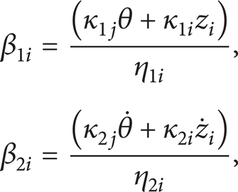
where i ∈ [1,2, 3,4], j ∈ [f, r], κ1j, κ2j, κ1i, and κ2i are the weighting factors, and η1i and η2i are the scaling factors.
All membership functions for the input and output fuzzy variables use triangular distribution (Figure 2) for easy calculation.
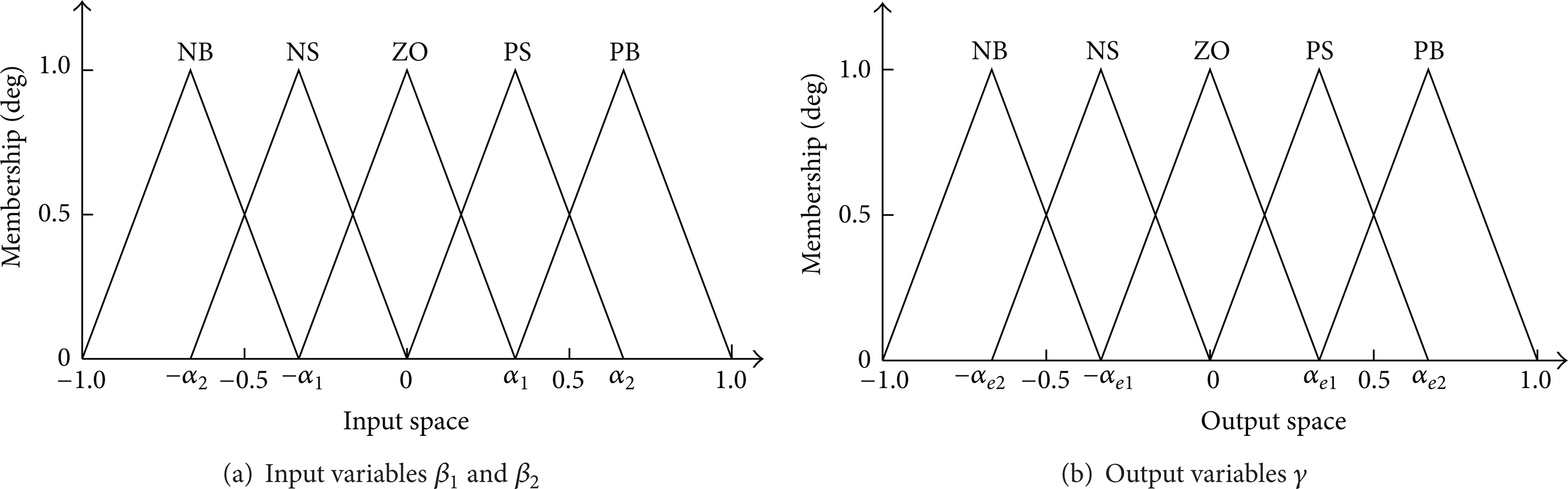
Membership functions for the input and output variables.
Considering the limited bandwidth of the hydropneumatic actuator (less than 6 Hz), a low-pass filter is added to the bottom hierarchy controller to reject high-frequency signals from the top hierarchy controller output force. The transfer function G(s) of the second-order low-pass filter is described as follows:

where ω d is the angular frequency set as 2 × π × 6 rad/sec and ζ d is a parameter determined by the phase delay between output and input signals, which is set to 0.7 in simulations.
3.2. Bottom Hierarchy Controller
A schematic of the hydropneumatic spring is shown in Figure 3. The relationship between the desired control force F and the required flow q c is obtained from the nonlinear mathematical model of the hydropneumatic spring [13] as follows:

where

where pg0 is the initial inflation pressure, vg0 is the initial inflation volume, Aeff is the effective area of the master piston, n is the polytropic index of the gas (1.0 to 1.4), and C s is the damping coefficient, which is set to 6500 N·m/s for the rebound stroke and to 2500 N·m/s for the bump stroke.

Schematic of the hydropneumatic spring.
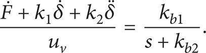
The structure of the proportional directional valve is shown in Figure 4. We assume that the oil source system can provide a sufficiently high and steady pressure p s and that oil pressure is sufficiently small to be ignored (p r = 0). If the import and export pressure difference is stable, then the relationship between valve flow characteristic q c (s) and control voltage u v (s) is simplified into a first-order dynamic relationship as follows:

where kb1 is linear with respect to the pressure difference between the import and export within a permissible variation range and kb2 is the constant delay time of valve correspondence.

Structure of the proportional directional valve.
Therefore, the relationship between the desired control force F and the required control voltage u v of the proportional directional valve is described as follows:
The algorithm of the bottom controller is shown in Figure 5.

Model-based bottom-layer controller for active hydropneumatic systems.
4. Controller Parameter Self-Tuning Based on a GA
Theoretically, the normal PID and fuzzy controllers for active vehicle suspension design can obtain optimal results if controller parameters are selected properly. However, a vehicle represents a complex oscillatory system with large degrees-of-freedom. The actual characteristics of a suspension system are nonlinear and the actual vehicle operates under variable conditions (i.e., according to changes in road conditions or sprung masses), which implies that system characteristics vary with time.
Moreover, the principle for determining the parameters of the PID and fuzzy controllers remains unavailable. Previous studies [14–16] have not yet presented the detailed process for determining membership functions. However, a traditional fuzzy controller design completely depends on an expert or experienced operator to establish a fuzzy rule database [17, 18]. This knowledge is generally difficult to obtain, and achieving a specified control performance is a time-consuming adjustment process. Moreover, a fuzzy logic controller needs to adapt easily to significant changes in system parameters. Ideally, system parameters are selected reasonably instead of depending solely on the subjective experience of a designer. Similar problems occur in deriving the three key parameters of a PID controller [15]. Therefore, optimal vehicle performance is essentially achieved by adapting the parameters K Pj , K Ij , and K Dj of a PID controller and the scaling factors η1i and η2i, gain values G Fi , and membership function (determined by α1, α2, αe1, αe2) of a fuzzy controller.
Considering a hybrid intelligent system that involves a combination of at least two intelligent technologies, for example, fuzzy logic and neural network [19], is a growing trend. In [19, 20], the learning ability of a neural network was used to tune the parameters of the membership function of fuzzy inference systems. In [21], the adaptability of the combined fuzzy PID model that adopts a GA was briefly introduced. The GA approach has received increasing attention because of its advantages over conventional optimisation [22–24], which make it a powerful technique for self-tuning parameters of hybrid active suspension controllers. In the current study, the GA method is applied to tune the parameters of a combined controller for effective active suspensions during an actual driving cycle (Figure 6).

GA-based self-learning of fuzzy PID control parameters.
A GA is not required to process each moment during online parameter tuning because of the following reasons.
If the self-learning process is running at all times, then the required high CPU performance results in high costs.
A membership function depends on the statistical dynamic properties of a vehicle that is travelling on a section of a road. The unsatisfactory performance of a control system at one point does not indicate imperfect controller efficiency throughout relative sections of the road.
Control precision for the next moment cannot be guaranteed even when optimal controller parameters are updated in real time because of the uncertainty of road inputs.
In practice, a GA-based self-learning process is only initiated when the defined performance index of vehicle dynamics exceeds a threshold for a certain period (called debounce time in this paper). As shown in Figure 6, the control performance monitor module is described as follows:
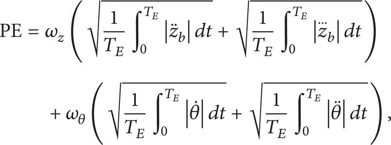
where PE is the comprehensive index of the control systems,
In this study, the optimised parameters comprise 38 variables, including the PID controller, scaling factors, gain values, weighting factors, and membership function elements determined by the fuzzy controller. If a vehicle is assumed to travel in a straight line (as in most cases) and the control system aims to minimise vertical and pitch accelerations of the vehicle body, then the left and right fuzzy controller parameters are regarded as the same. Equation (8) is transformed as follows:

where i ∈ [1,2, 3,4], j ∈ [f, r],

Therefore, the optimised parameters are reduced to 20 variables and the optimisation process is accelerated.
The current study deploys a performance index for active suspensions to minimise vertical and pitch accelerations of a vehicle body and achieve vehicle riding comfort with the following equation:

where
The GA-based optimisation process uses a binary map model of chromosome encoding, as shown in Figure 7. Firstly, the GA program is initialised (i.e., setting initial population size to 25, crossover rate to 0.45, variation rate to 0.05, maximum generation to 100, and iteration accuracy to 1e–4). Secondly, the feasible region of various control parameters is estimated based on experience. The controller parameter code (i.e., the chromosome) is generated during GA self-learning process and the corresponding decimal variable values are searched via a decoding method. The obtained parameters are applied to the closed-loop control program of the active hydropneumatic suspension system and cosimulation is activated. The fitness function value based on (17) is calculated according to the vertical and pitch accelerations of a body, which are measured from the vehicle dynamic model. Change in the direction of the fitness function value determines whether a code is inherited or abandoned by the next generation. This process is repeated with the new generation until the best individual fitness is obtained and the setting control accuracy of group average fitness is satisfied, thus ending the iterative process. The results are stored in a data file.
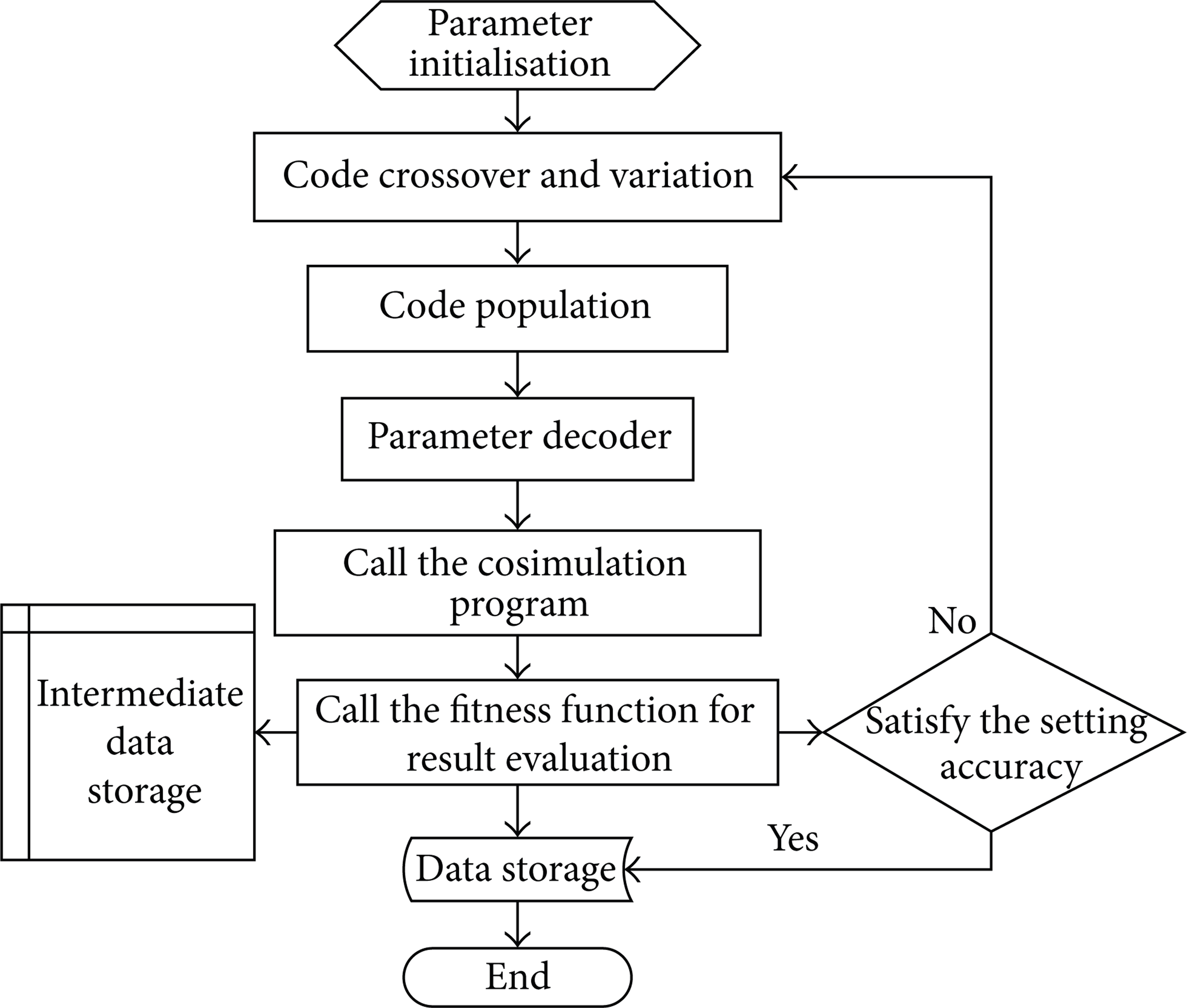
GA optimisation process for the control parameters.
5. Virtual Development Platform Design for Active Hydropneumatic Suspension Systems
The proposed control algorithm is edited in MATLAB/Simulink and implemented on a multibody dynamic vehicle model established in ADAMS/View by using a data exchange interface (Figure 8). Dynamic state variables from the vehicle dynamic model are passed on as inputs to the control system across the interface. Consequently, the control system performs calculations and sends instructions to drive the actuators and maintain desired vehicle behaviours. The monitor displays the changing process of important vehicle dynamic variables during cosimulation. The control parameters are adjusted to maintain consistency of the active hydropneumatic system in terms of state and action. The GA process is then performed to optimise the available parameters until control accuracy is satisfied.

General program of the proposed controller for active hydropneumatic suspension systems.
6. Analysis of the Simulation Results
Simulations of active vehicle suspension under different driving conditions are performed by using virtual environments. By considering common input conditions of a vehicle, simulations for vehicles with passive and active suspensions that are running on C-level random roads at a speed of 15 m/s are carried out. The main parameters of the control system used in the simulations are listed in Table 1.
Parameters used in the simulations.

The cosimulation results in the time and frequency domains, including vertical and pitch accelerations of a vehicle body, are shown in Figures 9 and 10, respectively. Compared with the vehicle with a passive suspension system under the same conditions, vehicle riding comfort is improved in the vehicle with a hydropneumatic suspension system by using the proposed GA-based hierarchical control scheme with a low frequency (below 6 Hz). Vertical vibration and pitch accelerations of the vehicle body are reduced. The peak values of the power spectral density of these accelerations are effectively attenuated.

PSD of vertical acceleration.

PSD of pitch acceleration.
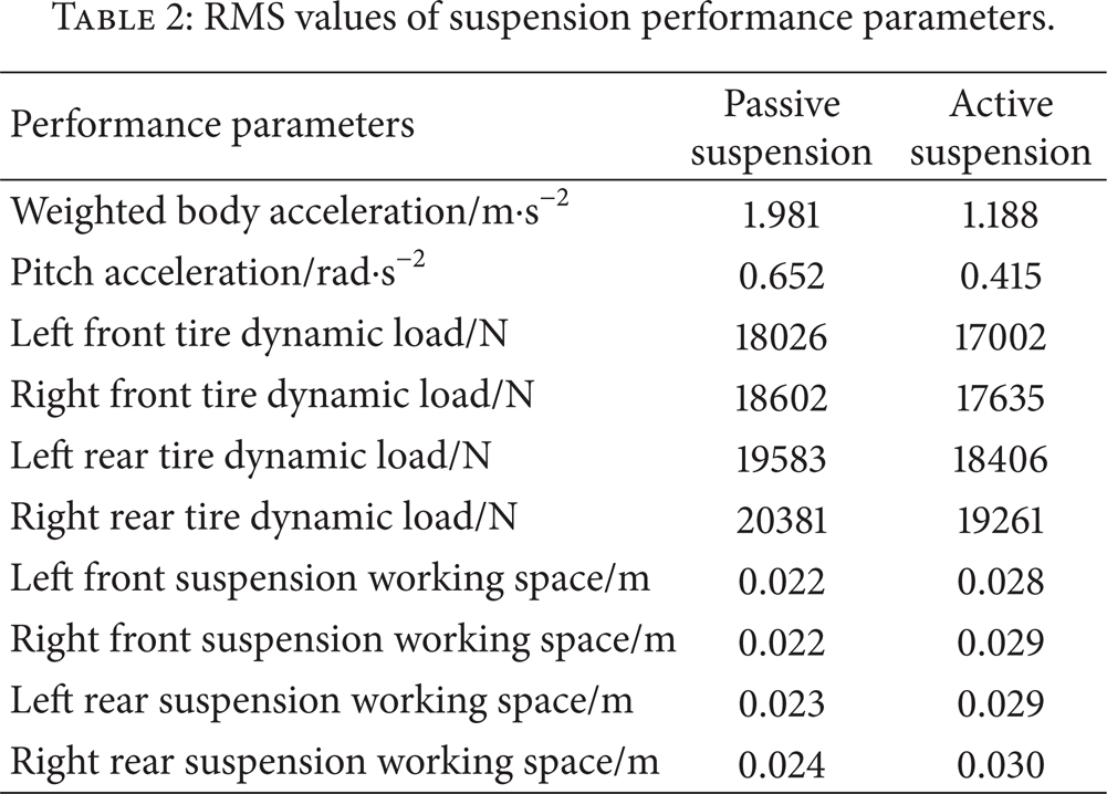
The RMS values of the performance parameters of the passive and active suspension systems are shown in Table 2. Compared with that of the passive suspension system, the value of the uncomfortable parameter of the active suspension system [25] is reduced by 40%, whereas pitch acceleration is reduced by 35%. Moreover, wheel adhesion property is improved as dynamic load is reduced by 5%. Improving vehicle riding comfort is always countered by increasing suspension dynamic travel. Although the dynamic travel of the proposed suspension is longer than that of a passive suspension system, the proposed system satisfies the limiting conditions; that is, the maximum allowed distance apart from the static balance position is ± 0.1 m and the RMS value for avoiding limiting stopper collision is 0.033 m.
RMS values of suspension performance parameters.
The self-tuning of parameters in response to various road excitation values from the designed active hydropneumatic suspension system is illustrated in Figure 11. At the beginning, the vehicle travelled on good road condition at 15 m/s. When road condition deteriorates from t = 20 s to t = 40 s, vertical acceleration increases to 0.35 g. The self-tuning program is activated at t = 25 s. Control performance cannot be reduced significantly and irregularly during the initial self-learning stage of the GA process because the process tunes control parameters within the limited basic optimal feasible region. The self-tuning process is terminated at t = 72 s after five to six generations, which last approximately 50 s. The new parameter values are simultaneously saved and applied to the controller.
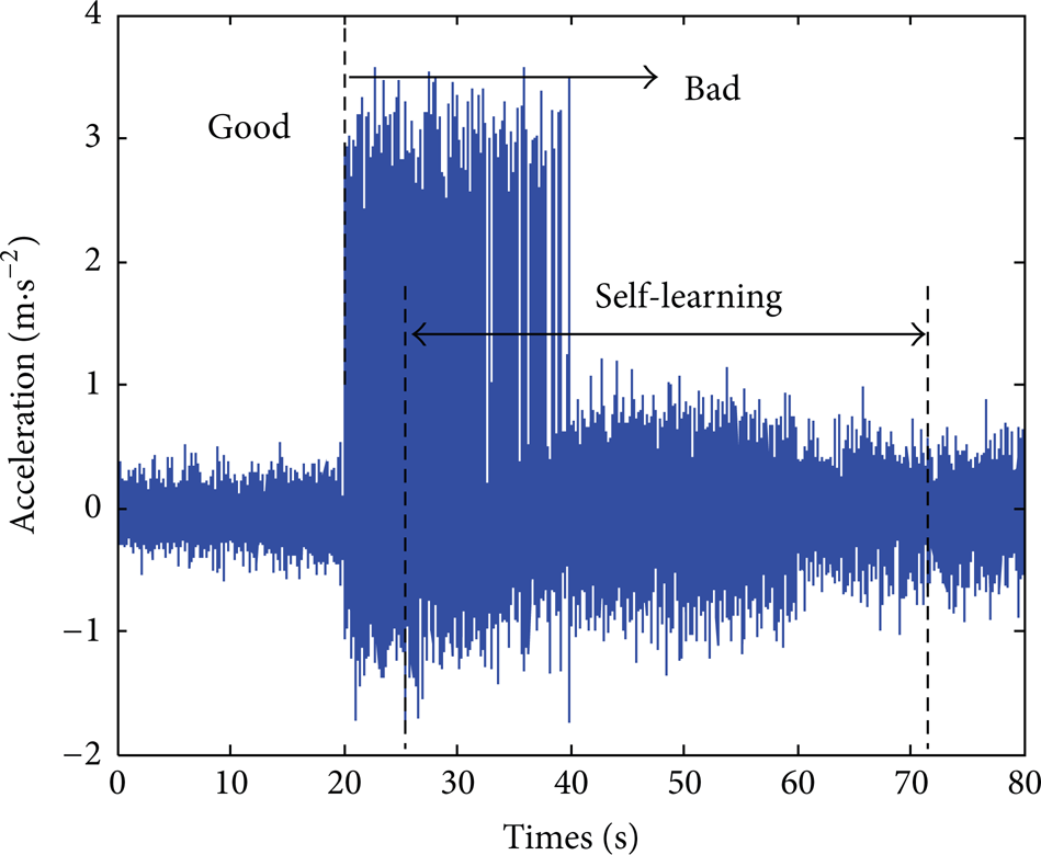
Self-adaptation of the controller under changing road conditions.
Therefore, the proposed active hydropneumatic suspension system effectively reduces peak values of vehicle body accelerations, particularly within the most sensitive frequency range of human perception, and attenuates excessive wheel dynamic load to enhance the performance of wheel/road adhesion. Moreover, the proposed control system exhibits good robustness and self-adaptation capability. Riding comfort and handling stability of a vehicle are significantly improved by using the proposed active hydropneumatic system.
7. Conclusion
This study proposes a new hierarchical control strategy for a bandwidth-limited active hydropneumatic suspension system that considers unpredictable road excitation and strong nonlinearities associated with the vehicle dynamic model and the hydropneumatic spring. The top hierarchy controller combines a PID and fuzzy logic controllers, whereas the bottom hierarchy controller is derived from a nonlinear model of a hydropneumatic spring and actuator. Moreover, a GA-based self-tuning strategy is presented to search for the time-varying parameter values of suspension controllers. The cosimulation results show that the optimised parameters of the hierarchical controller significantly improve vehicle riding comfort and exhibit a powerful self-adaptive response to changing road conditions. Applying a GA to optimise controller parameters provides the feasible region with credibility for vehicle field tests. Moreover, a GA provides guidelines and references to adjust and configure experiments on controller parameters as well as validating experiments on the final vehicle.
Conflict of Interests
The authors declare that there is no conflict of interests regarding the publication of this paper.
Footnotes
Acknowledgments
This study was supported by the National High Technology Research and Development Program of China (2012AA110701) and the National Natural Science Foundation of China (51375313 and 51305269). The authors gratefully acknowledge these support agencies and the anonymous reviewers who provided invaluable references and suggestions for this study.