
Abstract
The present work aims at revealing the formation mechanism of white layer and understanding the effects of tool wear and cooling/lubrication condition on white layer when hard milling H13 steel with coated cutting tools. Hard milling experiments were carried out, and tool wear and its effect on formation of white layer were investigated. Compared to dry cutting condition, CMQL (cryogenic minimum quantity lubrication) technique can obviously reduce tool wear and prolong tool life owing to its good cooling and lubrication properties. The optical images of the subsurface materials indicate that the formation of white layer is related to tool wear; moreover, the thickness of white layer increases with the increase of tool wear. SEM (scanning electron microscope) images and XRD (X-ray diffraction) analysis confirm that the formation of white layer is mainly due to the mechanical effect rather than the thermal effect. It also proves that white layer is partly decreased or can be totally eliminated by optimizing process parameters under CMQL cutting condition. CMQL technique has the potential to be used for achieving prolonged tool life and enhanced surface integrity.
1. Introduction
During metal forming process, the die and mold components are usually subjected to high thermal gradients, mechanical shock, and contact with the high temperature metal [1]. Hardened steel is often machined to act as the die and mold components, which are often loaded close to their physical limits [2]. Certain critical conditions require that the geometrical integrity and the physical integrity of the machined die and mold components are very important because they affect service life, reliability, and life cycle cost [3, 4].
With the advances in cutting tool materials, high performance machine tools, and NC (numerical control) program technique, hard milling steel in its fully hardened states has been very popular in the die and mold industry [5, 6]. Although hard milling can offer many potential benefits and has become a realistic replacement for grinding and EDM (electric discharge machining) applications by selecting the proper cutting tools and cutting parameters [7, 8], tool wear is still one of the important issues to be solved. Tool wear can not only reduce tool life but also increase cutting forces, deteriorate surface finish, and result in tensile and/or residual stresses and white layer on the machined surface [9]. The white layer is a result of microstructural changes, and its structure is extremely different from the bulk materials. The white layer is often higher than the bulk materials, which is benefit to improving wear resistance of contact surfaces; however, the white layer is brittle and is often accompanied by tensile residual stresses, which is detrimental to the machined component's performances, such as fatigue life, antistress corrosion, and wear resistance [10–13].
The investigation on the white layer formation and its mechanical and physical properties has become an important subject in terms of the machined surface integrity. Generally speaking, the mechanical effect, the thermal effect, and the environmental effect are considered to be the three possible mechanisms for white layer formation in machining processes [14]. White layer may occur on the machined surface during hard cutting processes, especially when aggressive machining parameters are applied or a worn cutting tool is used [15–18]; moreover, the thickness of white layer increases with the increase of tool wear [19, 20]. On the contrary, Axinte and Dewes [21] reported that white layer or other microstructural changes did not form on the machined surfaces although the worn tools were used when milling hardened AISI H13 steel. Thus, it becomes apparent that there is some controversy to the occurrence of white layer after machining operations in hardened steel, and it is necessary to perform an in-depth analysis of the white layer generated in hard milling of hardened steel.
Hard cutting is usually carried out without any cutting fluids, while some researches favor the cutting fluids to be employed to minimize the thickness of white layer. During dry cutting processes, the surrounding air with low thermal conductivity makes the cutting tool edges undergo a high degree of thermal loading and mechanical stresses, which directly result in high tool wear rate. MQL (minimum quantity lubrication) technique can aid the cutting processes by lubricating the tool/workpiece and tool/chip interfaces. In order to improve the cooling capacity of the MQL technique, CMQL (cryogenic minimum quantity lubrication) system in which the compressed air is treated by the cryogenic generator and then fed to the cutting zone can effectively take away the generated heat due to tool/workpiece friction and energy lost during deforming the materials.
Owing to high hot hardness and high toughness, the die-casting dies and the forging dies are mainly made by AISI H13 tool steel at hardness ranging from 40 to 55 HRC. To the best of the authors’ knowledge, up to now there is some lack of knowledge about tool wear and its effect on white layer formation when hard milling AISI H13 tool steel under CMQL cutting condition. To address this, the paper aims at revealing the formation mechanisms of white layer and understanding the effects of tool wear and cooling/lubrication condition on white layer formation when hard milling H13 steel with coated cutting tools.
2. Experimental Works
2.1. Workpiece Material, Machine Tool, and Cutting Tool
The workpiece material used in this study is AISI H13 tool steel, its normal chemical composition and thermophysical properties are listed in Tables 1 and 2, respectively. The prepared H13 steel blocks (Figure 1) were 100 mm long, 97 mm wide, and 30 mm high. All the blocks were austenitized and then quenched and double tempered. The final hardness of H13 steel is 50±1 HRC, and the resulting microstructure is a tempered martensitic matrix with various evenly dispersed carbide precipitates.
Nominal chemical composition of AISI H13 steel.

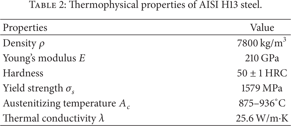
Thermophysical properties of AISI H13 steel.

Rectangular block of H13 steel and schematic of milling operation.
All the end milling tests were conducted on a three-axis vertical machining center (ACE-V500, Daewoo, Korea) with a maximum spindle speed of 10000 rev/min, a power output of 15 kW, and a feed rate up to 8000 mm/min.
The selected cutting tool was an end miller of 20 mm diameter (R217.29–2520.3–05.2.070, Seco Tools AB, Sweden). The indexable round inserts were used for hard milling operation, and the tungsten carbide (WC) substrate was coated with (Ti, Al) N/TiN multilayers. The geometric combination of the tool-holder and the indexable insert generated 0° rake angle and −4° axial rake angle. During hard milling process only one insert was used, which would eliminate the influence of the tool tip run-out on tool wear.
2.2. Experimental Setup and Procedures
2.2.1. Experimental Conditions
A kind of biodegradable synthetic vegetable oil (Bescut 173, Brugarolas S.A., Spain) was selected as the cutting oil, which is applicable at low temperatures down to −35°C. With the aid of the cryogenic generator and the oil-mist atomizer, the refrigerated compressed air and the microdroplets of the biodegradable vegetable oil were separately conveyed inside the nozzle, and then the mixture of oil and air was fed to the cutting zone (Figure 2). Two nozzles were placed so that the cutting tool was adequately covered by the cryogenic oil/air mixture. The nozzles were attached to the spindle arm to make sure that the oil/air mixture keeps spraying accurately. The milling experiments were carried out under down milling operation, in which dry and CMQL cutting conditions were employed, respectively. The experimental conditions are given in Table 3.
Hard milling conditions.


Experimental setup.
2.2.2. Tool Wear Measurement
According to the cutting parameters in Table 3 and the dimensions of H13 steel block in Figure 1, the time interval in a single cutting pass (along the feed direction) is approximately 0.67 min. The indexable insert was uninstalled from the tool-holder after a specified cutting passes (i.e., specified cutting time), and then the tool faces were carefully observed and pictures were taken, and then tool wear measurement was accurately performed with a handheld digital microscope (Dino-Lite AM413ZT, AnMo Electronics Corporation, Taiwan). After taking pictures and measuring tool wear, the indexable insert was again installed into the tool-holder for the next milling test.
According to ISO 8688-2:1989 (E), the recommended uniform flank wear criterion is 0.3 mm and a maximum flank wear criterion is 0.5 mm when end milling C45 steel or cast iron. However, the recommended tool should not have any coating or surface treatment. Therefore, tool life of the (Ti, Al) N/TiN coated inserts in the present research was determined by the number of cutting passes (i.e., cutting time), when the tool wear reached one of the following tool life criteria: (i) average flank wear, VB = 0.2 mm; (ii) maximum flank wear, VBmax = 0.4 mm; (iii) excessive chipping/flaking or premature fracture of the cutting edge.
2.2.3. Specimen Preparation and Test
After hard milling experiments, the small rectangular specimens (10 × 5 × 3 mm) were cut from the machined blocks at low cutting speed and enough coolant to avoid the further thermal damage. The specimens were mounted with cold setting-epoxy resins, and then the observation surfaces were gently ground and mirror-like polished to 0.25 μm finish. Meantime, some specimens from the unmachined H13 steel were also prepared following the same procedures.
Some of the polished specimens were etched in a solution of 5 vol.% HNO3 + 95 vol.% C2H5OH for 30 seconds. Optical microscopy (BX41RF, Olympus Corporation, Japan) and scanning electron microscopy (S-2500, Hitachi High-Technologies Corporation, Japan) were employed for observing the subsurface microstructure.
In order to confirm the presence/absence of tempered martensite and retained austenite in the machined and unmachined specimens, X-ray diffraction (XRD) tests were conducted using an X-ray diffractometer (D8 Advance, Bruker Corporation, U.S.A.) with a conventional Cu Kα X-ray radiation (λ = 1.5418 Å) from a source operated at 40 kV and 40 mA. The powder diffraction (2θ) patterns were recorded in 2θ steps of 0.02° in the 40–110° range. After X-ray scanning of the specimens, according to the peak positions and intensities, the background and peak positions were identified by means of High Score software.
3. Experimental Results and Discussions
3.1. Propagation of Tool Wear and Tool Life
During hard milling process, cutting tool materials are exposed to high mechanical stresses and thermal disturbances. As the cutting process progresses, the adhesion of (Ti, Al) N/TiN coating layers with the tungsten carbide substrate will weaken and finally the coating layers are disposed from the substrate materials. The thickness of the coating layers is very thin; basically, the peeling of the coating layers from the tungsten carbide substrate cannot change the geometrical angle of the cutting tools. However, the peeling of coating materials deteriorates the cutting condition of the tool, accompanied by elevated temperatures and increased cutting resistance, and then tool wear rate is accelerated.
On the initial stage of tool wear, the predominant wear pattern observed was nose wear under dry and CMQL cutting conditions. With the increase of cutting time, flank wear became severer and severer, and sudden microchipping also appeared on the rake and flank faces of the cutting tool. Figures 3(a) and 4(a) show the worn flank faces of the cutting tools after they met the tool life criteria as mentioned above. At the same time, flaking also appeared on the rake face of the cutting tool under both cutting conditions (Figures 3(b) and 4(b)). When VBmax was close to 0.08 mm under CMQL cutting condition, the excessive flaking on the rake face was observed. Figures 3 and 4 indicate that the localized flank wear was the dominant failure mode determining cutting performances and tool life under dry cutting condition, while the excessive flaking on the rake face was believed to be the dominant tool failure mode under CMQL cutting condition.
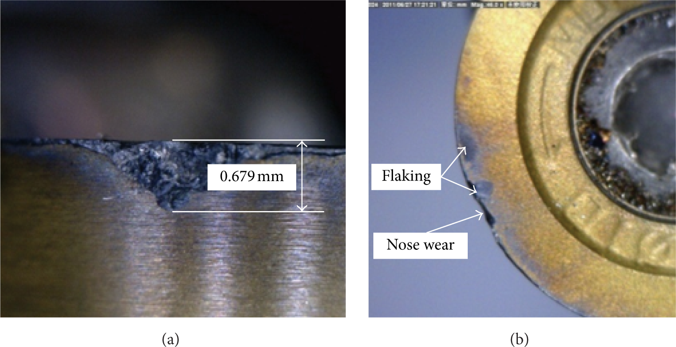
Tool wear morphology under dry cutting condition (cutting time is 373 min). (a) Flank face. (b) Rake face.
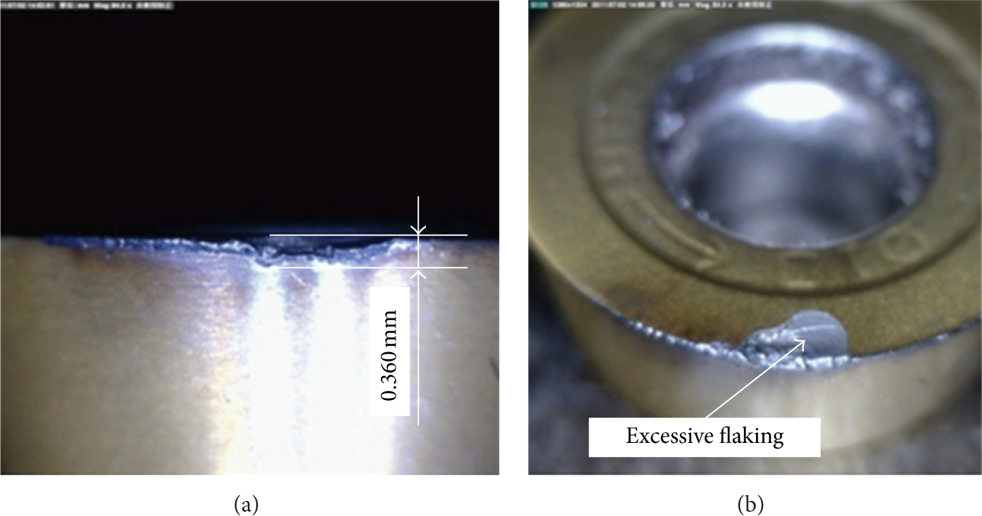
Tool wear morphology under CMQL cutting condition (cutting time is 957 min). (a) Flank face. (b) Rake face.
Figure 5 shows the relationship between the width of flank wear land (VB and VBmax) and cutting time. According to the tool life criteria, tool life under dry and CMQL cutting conditions is about 325 min and 905 min, separately. Compared to dry cutting, CMQL technique can significantly prolong tool life. It can be attributed to the good cooling and lubrication properties of the refrigerated compressed air and the microdroplets of cutting oil, which are useful to improve the cutting performance of the cutting tool. By means of the high-speed compressed air, the microdroplets of the cutting oils can effectively penetrate the tool/chip and tool/workpiece interfaces. Consequently, oil film with lower shear strength than the work material appears at the tool/chip and tool/workpiece interfaces, which can reduce the interface friction. Meantime, the low-temperature compressed air with high cooling capacity can effectively reduce the temperature of the cutting zone though it is not able to flush away the chips. It is reasonable that the cryogenic oil/air mixture has the ability to improve cutting performances and prolong tool life under CMQL cutting condition.
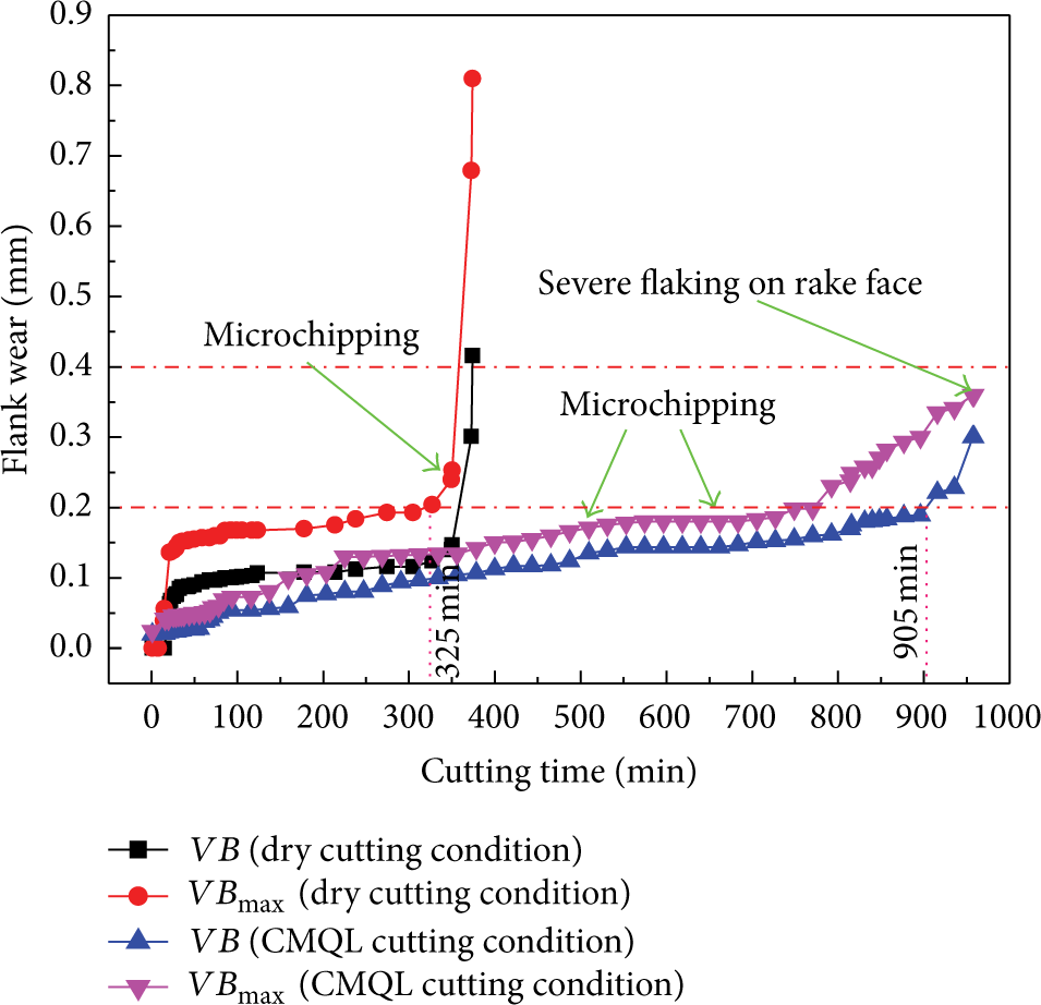
Tool wear progression under different cooling/lubrication conditions.
3.2. White Layer Analysis by means of Optical Microscope and SEM
In order to investigate the effect of tool wear on microstructural alteration at the subsurface of the machined H13 steel, sixteen specimens were selected according to the value of tool flank wear under dry and CMQL cutting conditions (Table 4). Under dry cutting condition, when VBmax is 0.170 mm, very thin white layer exhibits beneath the machined surface (Figure 6(a)), while the white layer thickness reaches up to about 42 μm when VBmax increases up to 0.679 mm (Figure 6(b)). CMQL technique can generate relatively low tool wear rates and small width of the flank wear land, which also partially reduces the possibility of white layer formation. As a result, except specimen CMQL-8 (Figure 6(d)) in which the white layer thickness is less than 10 μm, no obvious white layers are observed under other CMQL cutting conditions even when VBmax increases up to 0.238 mm (Figure 6(c)). The optical images indicate the subsurface microstructure of the machined H13 steel changes under the common actions of the larger thermal and mechanical loads due to the severe tool wear. Moreover, the white layer thickness increases with the increase of tool wear. In addition, the experimental results also prove that the application of CMQL can partially reduce or totally eliminate the white layer formation.
Machined specimens with different width of flank wear land.


Subsurface structures of hard milled specimens observed by optical microscope. (a) Dry-6. (b) Dry-8. (c) CMQL-7. (d) CMQL-8.
The SEM images in Figure 7 indicate that the subsurface of the machined H13 steel exhibits obvious plastic deformation under dry and CMQL cutting conditions. As shown in Figure 7(a), the microstructure of the subsurface materials is obviously different from that of the bulk materials at the initial wear region under dry cutting condition. The grains in the subsurface are subjected to extrusion, which are crushed and stretched; finally, the white carbide particles are distributed in the grain structure. With the increase of the tool flank wear, the much more severe plastic deformation results in the visible original grain structure in the unmachined H13 steel (Figure 7(d)) being replaced by the dense structure with no obvious grain boundary (Figures 7(b) and 7(c)); moreover, the structure also shows the noncrystal orientation. The very fine grain structure of the subsurface materials mainly results from the mechanical effect rather than the thermal effect [22, 23]. The reason is that a majority of the cutting heat was quickly taken away by the high-speed flowing chips. Consequently, the instantaneous surface temperature of the machined workpiece is relatively low and cannot exceed the austenitizing temperature of H13 steel.
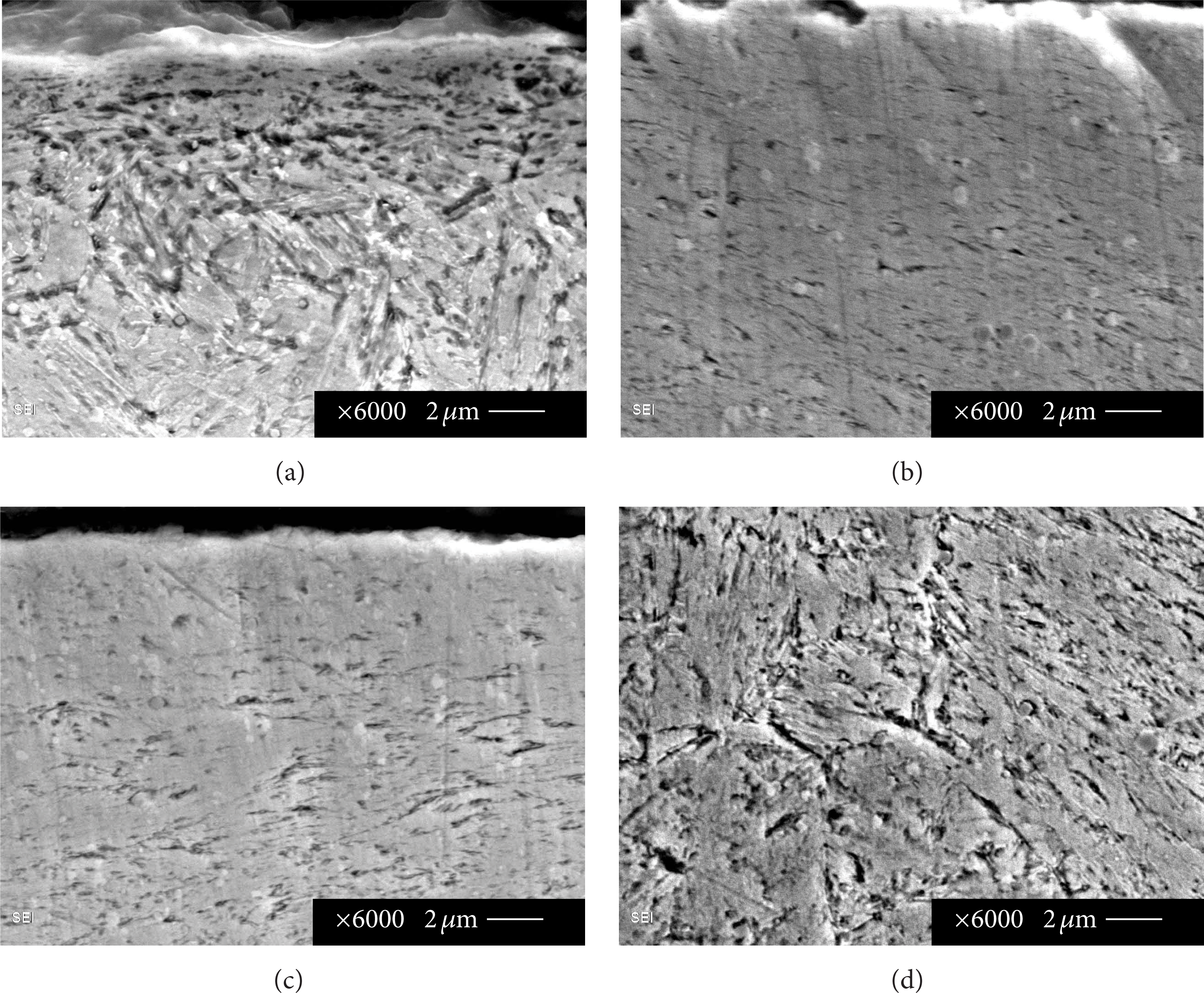
SEM images of different specimen. (a) Dry-1. (b) Dry-8. (c) CMQL-8. (d) Unmachined H13 steel.
3.3. X-Ray Diffraction (XRD) Analysis
As little information regarding the microstructure of the white layer can be acquired from the optical and SEM images, it is necessary to employ XRD technique to quantitatively identify the microstructural phase composition in the machined and unmachined specimens. Figure 8(d) shows the phase analysis on the unmachined H13 steel specimen, which has three peaks at 44.67°, 82.33°, and 98.94° standing for α(110), α(211), and α(220), respectively. On the contrary, no obvious diffraction peaks about the γ R -phase (retained austenite) are scanned. That is to say, the unmachined H13 steel which was quenched and double tempered is mainly composed of tempered martensite (α-phase) with various evenly dispersed carbide precipitates.
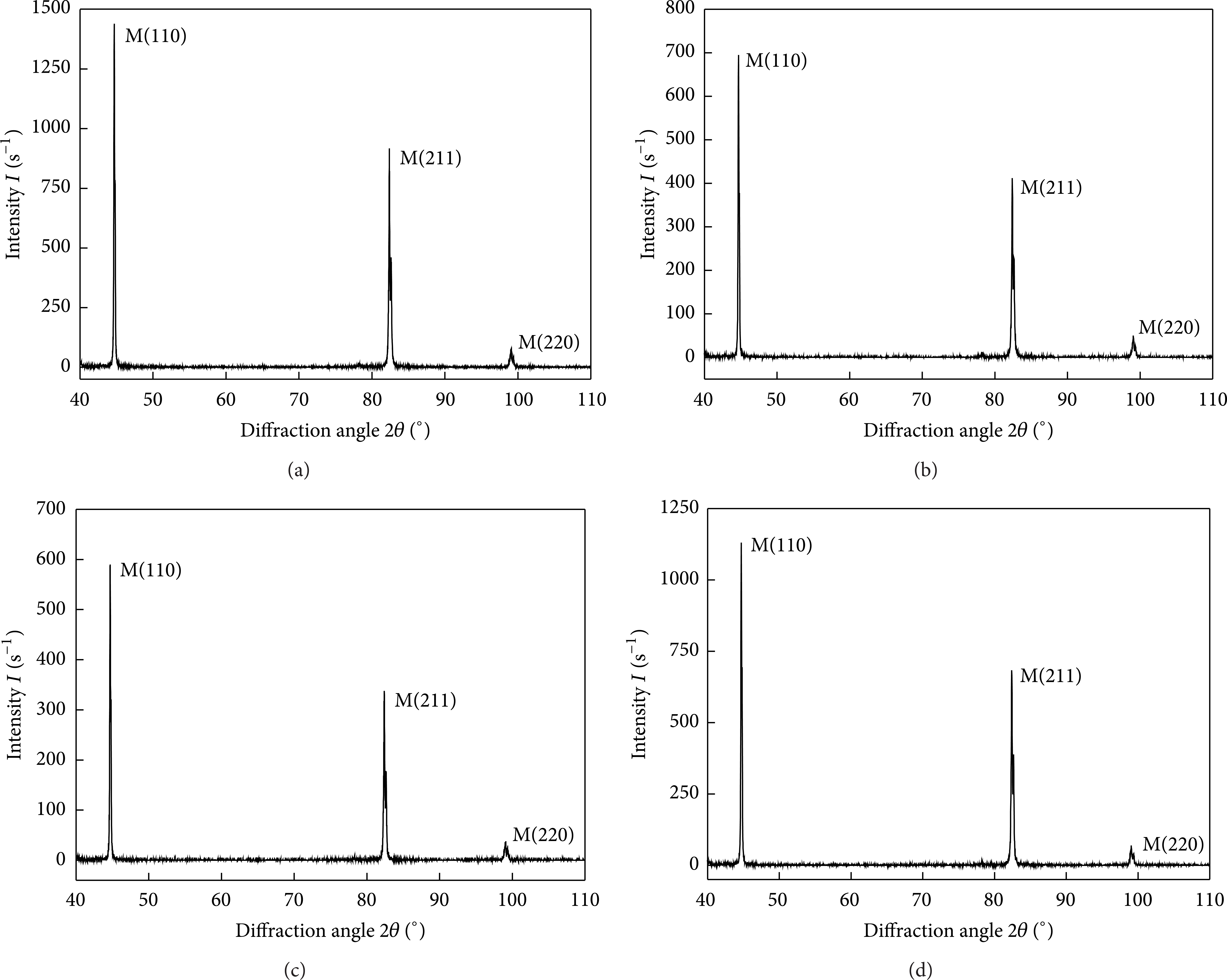
X-ray diffraction analysis on different specimen. (a) Dry-1. (b) Dry-8. (c) CMQL-8. (d) Unmachined H13 steel.
When the specimens with the white layer are investigated, the X-ray phase analysis shows the three same diffraction peaks (Figures 8(a)–8(c)). It proves that tempered martensite (α-phase) exists in the white layers under both cutting conditions. In particular, the magnitude of tool wear and cooling/lubrication condition can change the peak intensity of α-phase. X-ray phase analysis on the unmachined H13 steel surface and the machined H13 steel subsurface further indicates that the white layer generated during hard milling process is mainly composed of fine α-phase (tempered martensite) and other carbides, which is produced by the severe plastic deformation rather than the recrystallized γ R -phase (retained austenite), which is the result of sudden microstructural phase transformation due to rapid heating and cooling.
4. Conclusions
In the present work, an experimental analysis of tool wear and white layer formation in hard milling of AISI H13 steel under dry and CMQL cutting conditions has been carried out. The following conclusions can be drawn from the work presented in this paper.
The formation of white layer is related to tool wear; moreover, the thickness of white layer increases with the increase of tool wear.
SEM and XRD analyses confirm that the mechanical effect rather than the thermal effect is the main mechanism of white layer formation when hard milling H13 steel.
The white layer is partly decreased or can be totally eliminated by optimizing process parameters under CMQL cutting condition. CMQL technique has the potential to be used for achieving prolonged tool life and enhanced surface integrity.
Conflict of Interests
The authors declare that there is no conflict of interests regarding the publication of this paper.
Footnotes
Acknowledgments
This work was supported by the financial support from the National Natural Science Foundation of China (51175309) and Major National Science and Technology Project (no. 2012ZX04006011).