
Abstract
This paper presents the thermohydraulic performance of rectangular solar air heater duct equipped with V-shaped rectangular perforated blocks attached to the heated surface. The V-shaped perforated blocks are tested for downstream (V-down) to the air flow at Reynolds number from 2000 to 20000. The perforated blocks have relative pitch ratio (P/e) from 4 to 12, relative blockage height ratio (e/H) from 0.4 to 1.0, and open area ration from 5% to 25% at a fixed value of angle of attack of 60∘ in a rectangular duct having duct aspect ratio (W/H) of 12. Thermohydraulic performance is compared at different geometrical parameters of V-shaped perforated blocks for equal pumping power which shows that maximum performance is observed at a relative pitch of 8, relative rib height of 0.8, and open area ration of 20%. It is also observed that the performance of V-shaped perforated blocks was better than transverse-perforated blocks.
1. Introduction
Degradation of fossil, fuels due to increasing world population, industrialization and urbanization gives rise to develop highly efficient and compact thermal systems. Moreover, there is a serious need to stimulate the contribution of renewable energy resources by enhancing the performance and developing the more compact economic viable thermal systems. From many renewable energy resources, solar energy is one of the brightest and nonexhaustible sources of energy which can only supply the increasing demand of energy. In the last few decades, performance of upgradation of energy exchange devices utilized for collection of solar energy is increasing rapidly. Flat plate solar energy collector is incontrovertible one of the simplest and cheapest heat exchanger widely used for air heating applications. Flat plate collector is heated by exposing the solar radiation on it, which transfers heat to the air flowing through the system mainly by convection. Due to low heat transfer coefficient between absorber plate and flowing air, the performance of solar air heater is poor. In order to make solar air heater efficient, heat transfer rate from absorber plate to flowing air needs to be increased in solar air heater duct. An artificial roughness in the form of small wires is widely used method for the enhancements of convective heat transfer which creates turbulence at heat transfer surface. Earlier studies carried out on artificial roughness in the form of small wires of different geometries like transverse ribs [1, 2], W-shaped ribs [3], arch shaped ribs [4], protruded roughness [5], inclined discrete ribs [6], V-shaped ribs [7], multi-V-shaped ribs [8], and multi-V-shaped ribs with gap [9].
Large size roughness elements such as ribs (small height projections), baffles (thin elements of greater heights), or blocks (the thick elements) give a higher heat transfer in gas turbine blade cooling channels and solar air heaters [10]. Due to the large height, solar air heater duct usually has high penalty of pressure drop which is a drawback of such roughness elements. Hot zones also develop in the wake of these elements because of flow separation and recirculation which leads to a worsening of the heat transfer from these zones [11, 12]. To eliminate these hot spots, an attempts are being made by researchesto overcome this effect by creatingperforation in the baffles [10, 13], detached ribs [14], and blocks [15, 16] which not only increases the heat transfer but also reduces pressure drop across the test section. The perforated elements allow a part of the flow to pass through the perforations, and hence the hot zone and form drag are reduced.
Hwang and Liou [17] investigated heat transfer in a channel with perforated fences and compared the thermal performance of three types of turbulence promoters, namely, solid, perforated, and slit types. Sara et al. [15, 16, 18] investigated the solid and perforated blocks attached to the heated surface in the duct. Effects of hole inclination, open area ratio, diameter of hole, and number of blocks on heat transfer were also examined. Karwa et al. [10, 13] investigated the half and fully perforated baffles attached to the heated surface. Enhancement of 79%–169% in Nusselt for fully perforated and 133%–274% for half perforated baffles was found. Half perforated baffles at a relative roughness pitch of 7.2 give the greatest performance of about 51.6%–75% over a smooth duct. Shin and Kwak [19] investigated five different shapes of holes in blockages wall. Buchlin [20]studied the heat transfer characteristics in a channel with various perforated rib turbulators by means of an infrared scanning radiometer. Nuntadusit et al. [11] carried out flow visualization of six different perforated blocks (made by acrylic) and examined the effects of hole inclination and location of hole on heat transfer characteristics in flow channel. In case of sold ribs, flow separates and does not reattach when relative pitch ratio is less than 7 (P/e < 7), while for relative pitch ratio greater than 7 (P/e > 7), the flow separates at the rib and reattaches in between the consecutive ribs region and a recirculating flow is established in just downstream of the ribs. Better performance is found for fully and half perforated baffles in comparison to solid baffles, when P/e < 10 [13]. Chamoli and Thakur [21] carried out the experimental work to study the effect of open area ratio and relative hole position of V-shaped perforated baffles of solar air heater. Their work covered the range of open area ratio of 12%–44%, relative hole position (l/e) 0.429–0.571 for fixed value of relative height of (e/H) 0.4, relative roughness pitch (P/e) of 5, and angle of attack (α) of 60°. It was found that maximum enhancement in Nusselt number and friction factor was found to be 2.2 and 5.2 times of that of smooth duct, respectively. The earlier studies have been listed in Table 1 that shows the all studies related to perforated baffles/blocks oriented in transverse position.
A summary of important feature of perforated baffles/blockages used by various investigators.

Literature reveals that no study is available in the past which shows thermohydraulic performance of V shaped perforated blocks. Thus, conclusion cannot be drawn regarding the effect relative blockages height, relative pitch ratio, and relative open area ratio of thermohydraulic performance of V-shaped perforated blocks. The perforations in the blocks enhanced the heat transfer rate due to acceleration of flow in the form of jets through these perforations which subsequently strike with the heated surface and mix with main flow. However, in most of the cases, blocks were transversely oriented in direction to the flow for same relative height. Earlier studies in the case of ribs showed that the V-shaping of transverse ribs results in considerably higher heat transfer due to the generation of secondary flows [7–9, 22, 23]. Consequently, investigating the effect of V-shaping of the block at different relative height, relative pitch, and open area ratio on thermohydraulic performance of rectangular duct for same pumping power was proposed. In this work, extensive experimental data has been collected on thermohydraulic performance as a function of geometrical parameters of these blocks, namely, relative blockage height ratio, relative pitch, and relative block pitch ratio.
2. Thermohydraulic Performance Criteria
In order to achieve better geometry, thermal as well as hydraulic performance both must be considered simultaneously. Zhang et al. [28] compared the ratio of Stanton number to friction factor with and without heat transfer promoter. Zimparov and Vulchanov [29] proposed performance evolution criteria which were based on entropy generation. Hwang and Liou [17] and Liou and Chen [14] suggested performance evolution criteria based on enhancement of Nusselt number of roughened duct over smooth duct for the same operating conditions. Another performance evolution criteria based on the ratio of effective thermal efficiency of roughened duct to effective thermal efficiency of smooth duct for the same operating conditions were proposed [30]. Thermo-hydraulic performance parameter η is proposed by Lewis and Karwa et al. [31, 32], which is useful to determine the effectiveness of enhancement of heat transfer promoter in comparison to smooth plate for same pumping power. It is expressed as

If thermohydraulic performance parameter is higher than unity, this ensures the usefulness of the transfer enhancement device. This parameter was used to compare the performance of different enhancement techniques [16, 33]. In this paper, value of thermohydraulic parameter for perforated V-shaped perforated blocks was calculated and compared at different geometrical and operating parameters.
3. Experimental Program
3.1. Detail of Experimental Setup
An experimental setup has been designed and fabricated to study the effect of V-shaped perforated rectangular blocks on thermohydraulic performance in a rectangular solar air heater duct. The schematic plan view of the experimental setup is shown in Figure 1.
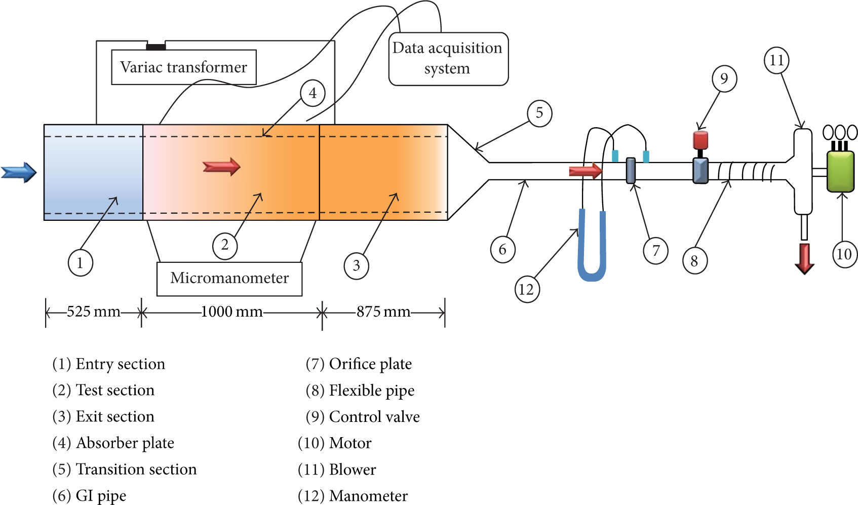
Schematic Plan View of Experimental Setup.
It consists of a wooden rectangular duct of dimensions 2400 mm × 300 mm × 25 mm in size. One side of duct is opened for inlet air and other side is fitted with MS pipe and blower fan. The entrance section, test section, and exit sections have a length of 525 mm, 1000 mm, and 875 mm, respectively, including the length of plenum on the exit side in order to minimize the end effects on the test section as per recommendation of ASHRAE standards 93–77 [34], which suggested that minimum entry and exit lengths are to be 5√WH and 2.5√WH, respectively.
For constant supply of heat flux to the absorber plate, an electric heating element is fabricated by combining six loops of nichrome wire in parallel and series, having a size of 1525 mm × 300 mm. These nichrome wires are fixed on 4 mm thick asbestos sheet, which was covered with strips of mica to keep a uniform distance between the wires. The desired values of heat flux can be supplied with the help of a constant voltage transformer connected across it. A glass wool of 76 mm thickness along with 12 mm thick wooden and 51 mm thermocol sheet is provided in order to minimize the heat losses from the topside of the heater assembly. The absorber plate of duct being GI sheet of 1925 mm × 300 mm size was painted black. V-shaped perforated blocks are attached to the underside of the plate. Figure 2 shows the cross section of the duct.

Cross-sectional view of duct.
In order to measure the mass flow rate of air through the duct, manometer connected to orifice meter was used. Two valves, connected in the lines, were used to regulate the flow rate of air. The pressure drop across the test section was measured with the help of a micromanometer having a least a count of 0.001 mm. Twenty-seven calibrated T-type thermocouples were attached at absorber plate to measure the plate temperature. Two thermocouples were used to measure the inlet air temperature and five thermocouples were used to measure the outlet air temperature.
4. Range of Parameters
Rectangular blocks were designed based on dimensions used by previous researches, namely, optimum angle of attack (α) 60° in case of V-shape ribs [7, 8, 33, 35]. For extensive study, five values of relative pitch (P/e) and four values of relative blockage height and five values of open area ratio (β) were considered. The open area ratio is defined as ratio of the area of the perforation to the block frontal area given by

where n is the number of hole in one limb. In the current work, open area rations were changed by changing the perforation hole diameter which is more effective than increasing the number of holes [15]. The geometry is shown in Figure 3. Table 2 gives the range of parameters.
Range of parameters.

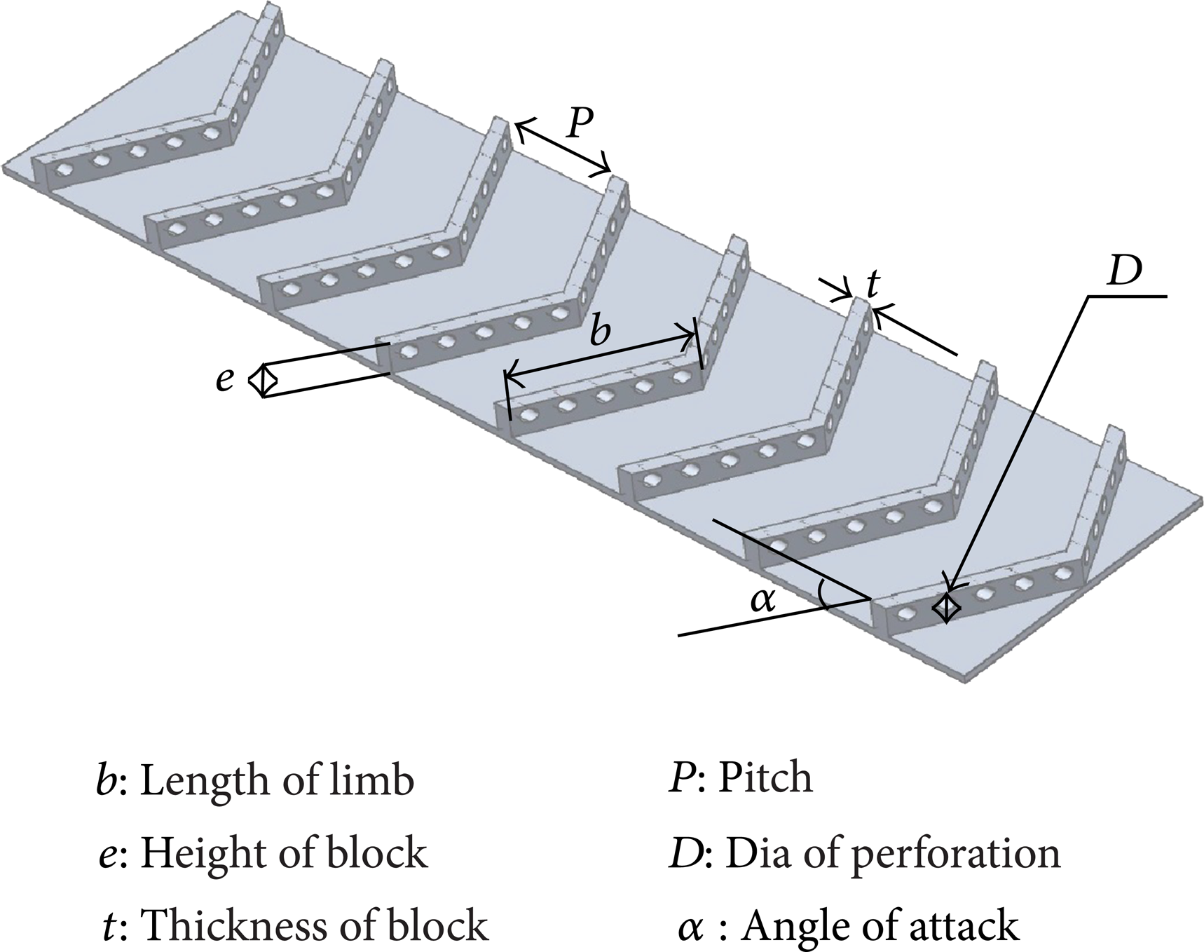
V-shaped perforated blocks.
5. Data Collection
The following parameters were measured under the steady state conduction.
Absorber plate temperatures at different location were measured.
Inlet air temperatures were measured at the inlet section of test section.
Outlet air temperatures were measured at the outlet section of test section.
Pressure drop across the orifice plate (Δh o ) was measured to calculate the mass flow rate.
Pressure drop across the test section (Δh d ) was measured.
6. Data Reduction
The experimental data for plate and air temperature at different location was recorded under steady state conditions for the given heat flux and mass flow rate of air.
The following expression has been used to determine mass (m) flow rate using pressure head differential (Δh o ) across the orifice plate:
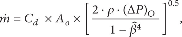
where ΔP o = ρ × g × Δh o × sinθ and C d is the coefficient of discharge.
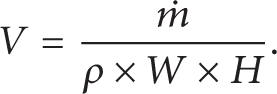
Velocity of air (V) is determined by using the mass flow rate calculated above:
Reynolds number (Re) for air flow through the test section is then determined as follows:

where ν is kinematic viscosity of air.
The heat transfer rate (Q) from heated plate to air has been determined using the mass flow rate (m) determined above and the temperature rise across test section:

where T i = (Ti1 + Ti2)/2 and T o = (To1 + To2 + To3 + To4 + To5)/5.
Heat transfer coefficient (h) has been calculated using heat transfer rate (Q) and average plate temperature:
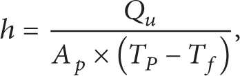
where average fluid temperature T f = (T o + T i )/2.
Area weighted plate temperature (T p ) is given by
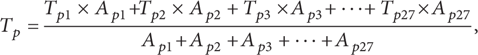
where Ap1 + Ap2 + Ap3 + ⋯ + Ap27 are area of heated plate which is divided into twenty seven parts.
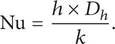
Nusselt (Nu) number has then been calculated using heat transfer coefficient (h), hydraulic diameter (D h ) of duct, and thermal conductivity of air as follows:
The friction factor (f) was calculated from the pressure head drop (ΔP d ) and flow velocity of test section (V) by using Darcy-Wiesbach equation:
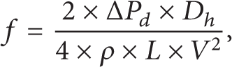
where ΔP d = ρ × g × Δh d .
Thermohydraulic performance parameter η was calculated by (1).
Based on the analysis of the errors, the maximum uncertainty in the experimental measurements with various instruments suggested by Hollman [36] has been calculated as follows:
Nusselt number = ±6.9%,
Friction Factor = ±4.43%,
Stanton number = ±7.32%.
7. Validity Test
Before starting the experimental work, validity test has been conducted from smooth duct and calculated Nusselt number and friction factor are compared with the values obtained from Dittus-Boelter equation (Nu = 0.023 × Re0.8 × Pr0.4) [37] and modified Blasius equation (f s = 0.085 × Re−0.25) [38] for Nusselt number and friction factor, respectively, as shown in Figures 4 and 5.

Comparison of experimental and estimated values of Nusselt number of smooth surface.

Comparison of experimental and estimated values of friction factor of smooth surface.
The average absolute deviation between experimental and predicted values of Nusselt number and friction factor has been found to be 3.18% and 1.89%, respectively, and these values ensure the accuracy of the data being collected with the experimental set-up.
8. Results
Thermohydraulic performance parameter for rectangular duct with perforated V-blocks, determined by using the collected data for various sets of values of geometrical parameters of blocks is discussed below. Experimental values have also been compared with results obtained from transverse-perforated blocks duct under nearly the same operating conditions.
Thermohydraulic performance of V-shaped perforated blocks is compared with the transverse-oriented perforated blocks for approximately the same geometrical parameters as shown in Figure 6. V-shaping of blocks helps to increase the thermohydraulic performance because of high heat transfer rate. It is due to fact that vortices of strong secondary flow moved along the limbs and the higher level of mixing turbulence when angled jets issuing from perforations reattach and mix with main flows as shown in Figure 7.

Comparison of thermohydraulic performance with previous investigation (Sara et al. [15]).

Formation of secondary flow, reattachment point, and mixing.
Figures 8 and 9 show the effect of Reynolds number on thermohydraulic performance at relative rib height of 0.6 and 0.8, respectively. These thermohydraulic performances decreases with increasing the Reynolds number but at a high Reynolds number thermo hydraulic performance is not significantly changed. It is also observed the maximum performance found at relative pitch of 8 for all Reynolds number.
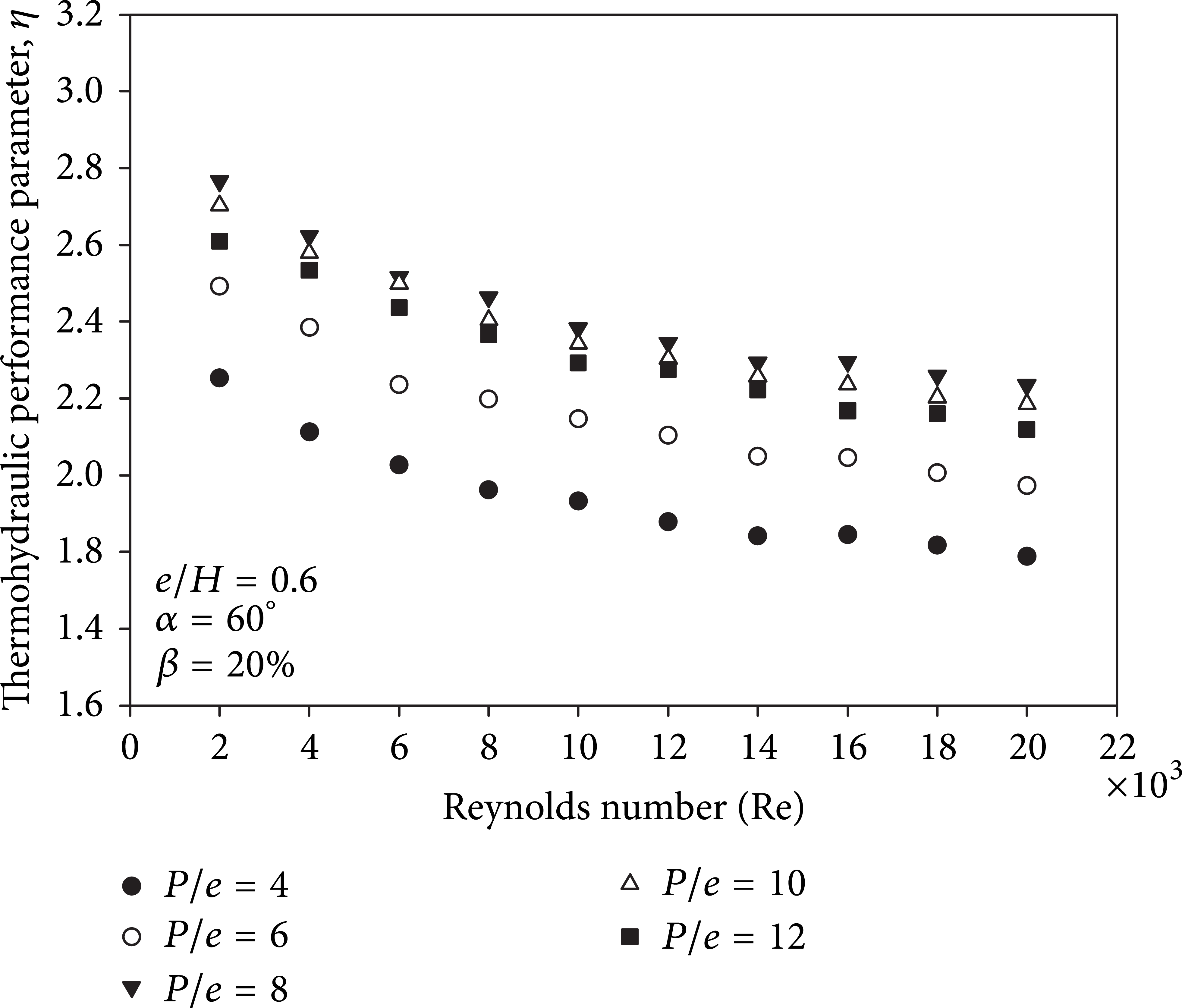
Effect of relative pitch ration on thermohydraulic performance.
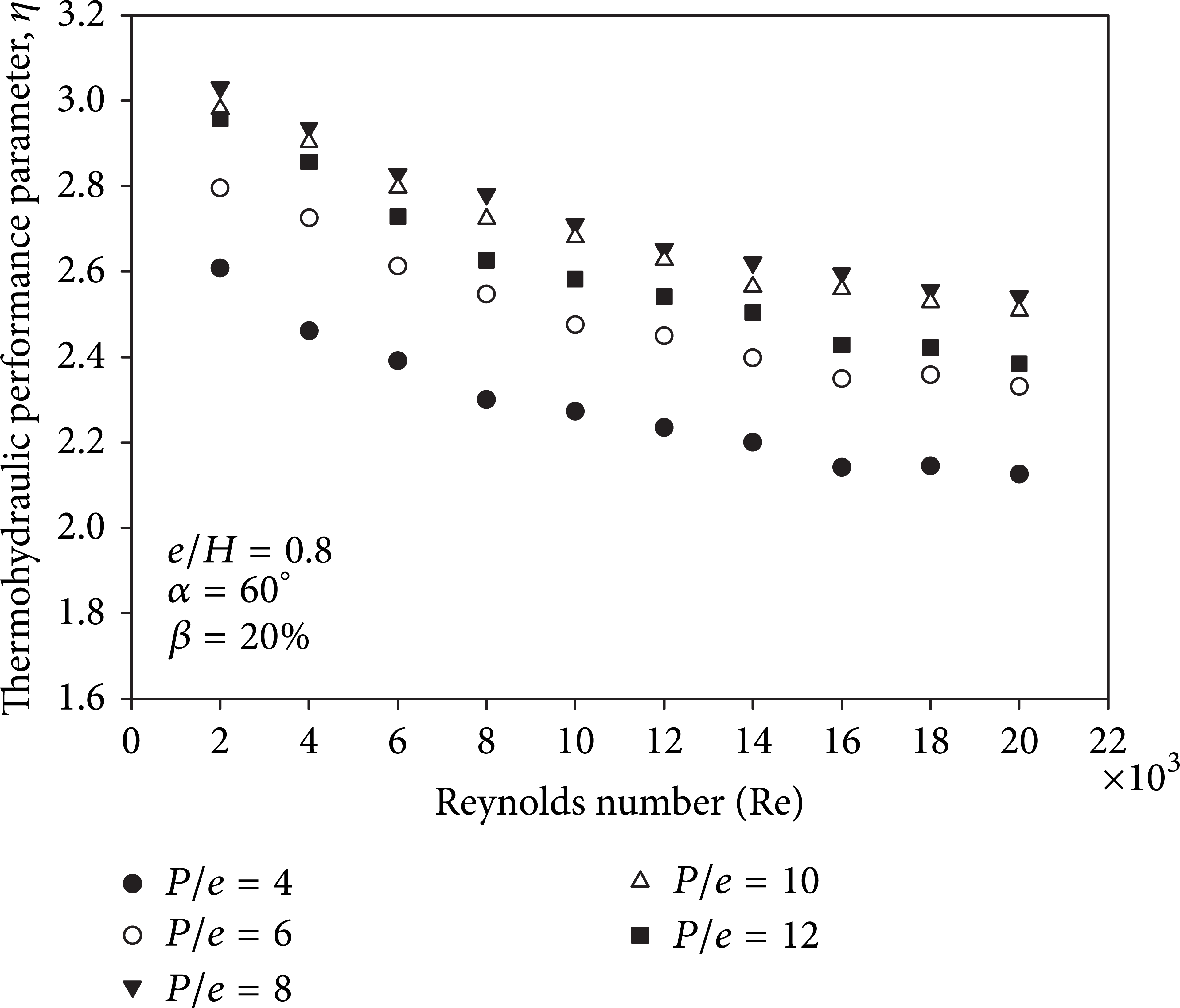
Effect of relative pitch ration on thermohydraulic performance.
Figure 10 shows the effect of relative pitch ratio on thermohydraulic performance at fixed relative rib height of 0.8, fixed open area ration of 20%, and different selective Reynolds number. It can be seen that the thermohydraulic performance increases with relative pitch ratio from 5 to 8, attains a maxima at a relative pitch ratio of 8, and thereafter it decreases with an increase in the relative pitch ratio for all Reynolds numbers. It may be due to fact that flow separation may occur downstream of a block, and reattachment of free shear layer may occur and mix with main flow, if relative roughness pitch (P/e), nearly equal to 8 and maximum thermohydraulic performance occurs.

Effect of relative pitch ratio on thermohydraulic performance.
Figure 11 shows the effects of relative rib height on thermohydraulic performance at different Reynolds number. Thermohydraulic performance increases with relative rib height attaining maximum value of 0.8 and then decreases for all Reynolds numbers. This may be due to fact as we increase the relative rib height beyond the 0.8, the flows experience the high resistance which leads to large pressure drop and lower thermo hydraulic performance.

Effect of relative height ratio on thermohydraulic performance.
To present the effect of open area ratio, the variations of the thermohydraulic performance with open area ratio are presented in Figures 12 and 13. These figures show the effect of open area ration on thermohydraulic performance at relative rib height of 0.6 and 0.8, respectively, but at a fixed relative pitch ratio of 8 where a clear maxima in plot can be observed. Thermohydraulic performance increases with open area ration attaining maximum value at open area ration of 20%, and thereafter decreases with an increase in the open area ratio. This is explained by the flow phenomenon as discussed below.

Effect of open area ratio on thermohydraulic performance.

Effect of open area ratio on thermohydraulic performance.
Thermohydraulic performance depends on open area ratio due to two reasons: (i) small diameter hole issuing highly accelerated jet from the perforation mix with main flow to promote the higher degree of mixing and thereby higher thermohydraulic performance, (ii) for a given axial distance, the higher the perforation diameter, the higher the radial expansion. If a diameter of hole is large enough in case of multiple perforations in blocks, radial expansion will interact with neighbouring jet-like flow with each other resulting higher degree of flow mixing. For open area ration from 5% to 20%, radial expansions of jet interact with neighbouring jet resulting in higher heat transfer and thermohydraulic performance, but after open area ration of 20% the flow velocities through the perforations will reduce, which may not be strong enough to accelerate the flow through the perforation, and hence the thermohydraulic performance due to this flow may be decreased.
9. Conclusions
An experimental study is carried to find out the effect of V shaped perforated blocks on thermo hydraulic performance in a rectangular duct in which one wall is equipped with V shaped perforated blocks and subjected to uniform heat flux. Wide ranges of Reynolds number (2000–20000) have been used and this corresponds to the actual condition of solar air heater.
The following conclusions have been drawn.
The effect of Reynolds number, relative rib height, relative pitch ratio, and open area ration on thermohydraulic performance has been studied at a fixed value of angle of attack of 60°.
V-shaped perforated blocks are found to be thermohydraulically better than transverse-perforated blocks operating at same condition.
Maximum thermohydraulic performance is obtained for relative pitch ratio (P/e) of 8, relative blockage height ratio (e/H) of 0.8, and open area ratio (β) of 20%, and its value is of the order of 3.
Footnotes
Nomenclature
Conflict of Interests
The authors declare that there is no conflict of interests regarding the publication of this paper.