
Abstract
A new 2-DOF microgripper, which can perform the processing of the objects assembly and biological cells injection, is designed and modeled in this paper. The clamping action of the microgripper with the x direction is completed, however, when anything is clamped by the end effector, which can be completely driven by an actuator generated in y direction, at lastclamping and pushing motion are realized. The flexure hinge, which takes place of the conventional joint, is used as the translational and rotational hinges in the new structure. Otherwise, the whole microgripper is monolithic processing, which can efficiently overcome the disadvantages of the conventional hinge with friction, backlash, anderrors caused by the hinge assembly. Firstly, a kind of novel microgripper is designed in this paper, which can accomplish two-dimensional independent motions including a separate grip and single track push without interfering with each other. The bridge type amplifying structure with two-end output is adopted in the gripper to increase the motion range and the capacity of the microgripper. The piezoelectric actuator with fast response and high resolution is used as the drive element. Secondly, the geometrical and kinematical models are established and the formulas of the amplifying ratio, stiffness, maximum stress, and the natural frequency of this model are calculated, respectively. Finally, the FEM (finite element modeling) based on ANSYS software is built up to validate the formulas.
1. Introduction
For the past few years, the microgripper was successfully applied in fields such as biology, medicine, and cell manipulation. Because the application and technology of the large size of manipulator have achieved a rapid development in the macroworld, many scholars pay more and more attention to the microworld using micromanipulator. However, it is very difficult to observe, operate, and control the object's micro/nanoscale motion with the naked eyes, especially the tiny motion in the microworld. With high magnified ratio microscope, a magnifying glass or other necessary and special equipment must be used to finish these operations [1–4]. The shape memory alloy and electromagnetic driven and piezoelectric ceramics (PZT) actuators are often adopted in the area of the micromanipulator [5–8]. But PZT is mostly used in the fields of the microgripper than others [9, 10], because of the advantages of the PZT in terms of fast response and high resolution, while its negative characteristics are hysteresis and nonlinearity. At present, many microgrippers with 1-DOF can be fabricated by monolithic processing method. For example, a new microgripper based on flexure hinge with five beams had been designed by Tian et al. [11], in which the PZT was employed as the actuator of the structure via lever amplification principle, which can obtain the large output displacement in the end effector. In addition, Kohl et al. [12] studied a kind of microgripper driven by shape memory alloy, and the maximum clamping stroke and gripping force of structure are 300 μm and 30 mN, respectively. Besides, Solano and Wood [13] investigated a polymeric microgripper for cell manipulation, which has a large displacement under the situation that low input voltage and temperature are given. The displacement with 262 μm occurrs under the function of the input voltage with 1.94 V and power force with 78 mW as testing the structure. Tang and Li developed 2-DOF dual mode PZT driven micromanipulator [14, 15].
Many kinds of microgrippers coming from the early studies can only perform a single clamp and finish two motions including clamping and pushing forward at the same time. Few literatures studied the microgripper with two separated movements in x and y directions. According to this requirement, a kind of novel microgripper based on single bridge type amplifying structure is proposed, which can realize two degrees of freedoms including single clamping and single pushing in the x and y directions, respectively. In addition, the whole structure is manufactured with monolithic material, which overcomes the disadvantages of the assembling and friction. The displacement of the structure is derived by the flexure deformation of the material, so stroke is limited, but the single bridge type amplifying structure has solved that problem perfectly. The piezoelectric actuator with fast response and high resolution is used as the driving element.
This paper is arranged as follows. In Section 2, a kind of novel microgripper is proposed in this paper, which can complete 2-DOF independent motions including a separated gripping and pushing action, thus interference will not happen between the gripping motion and pushing motion. In Sections 3 and 4, the geometrical and kinematical models are established and the formulas of the amplifying ratio, stiffness, maximum stress, and the natural frequency of model are calculated. In Section 5, the FEM model based on ANSYS software is built up to validate the formulas. Some conclusions are given in Section 6.
2. Structure Design of the Microgripper
2.1. One-Dimensional Flexure Amplifying Structure
Generally, there is a limit when the end effector will grasp an object, if the output of the end effector is only the output of the piezoelectric ceramics actuator; otherwise, the result produced is not perfect. In addition, due to the limited deformation of material itself, the output displacement is also not a large range. A kind of straightforward or hybrid amplifying mechanism is presented for overcoming the disadvantages of the small motion, which can be generally called intermediate transition mechanism (ITM). The purpose of using ITM is that a small displacement of PZT produced is used to transform into a large motion for the micromanipulator [12]. Two single chain bridge type amplifying mechanisms are placed in the x and y plane along with the y axial symmetry as shown in Figure 1. Moreover, the structure chart and schematic diagram for single chain bridge type amplifying mechanism are shown in Figures 1(a) and 1(b), respectively. We can observe that A and B points are taken as the input of the structure, while C and D are taken as the output of it. In addition, a single chain bridge type amplifying mechanism is also symmetric along with the y axis, which can achieve the good decoupling result for input and output symmetry. Half spherical notch hinge that has better characteristics of transforming displacement and force is adopted as the deformed hinge for the microgripper. The situation for forcing deformation of mechanism is shown in Figure 1(b) and the dash line of which expresses the condition that transforms after forces are exerted.

Amplifying mechanism. (a) Single chain bridge type amplifying mechanism. (b) Motion and force diagram.
One DOF for the microgripper is shown in Figure 2. The two jaws of the gripper which can be observed from Figure 2 have symmetric distribution along the y direction. The two jaws can be actuated at the same time or only one jaw can be driven while the other is not. It can be observed that the two jaws can clamp objects independently and they are noninterfering, and their motion trajectories can be solely controlled.

One DOF of microgripper structure diagram.
2.2. Microgripper Mechanism
The single DOF movement for the microgripper has been analyzed in the previous section, which can produce the mutual independent motion; so it has the benefits of manipulating gripper and clamping objects. But it can only finish the simple tasks by the single microgripper. However, in the field of microinjection, a kind of minimum injection needle that has only the diameter about 0.1 μm–0.5 μm can be infibulated under the high power microscope and then pushed ahead in another direction, which is called a process of injection. So a novel type of microgripper is proposed for finishing that process as shown in Figure 3.
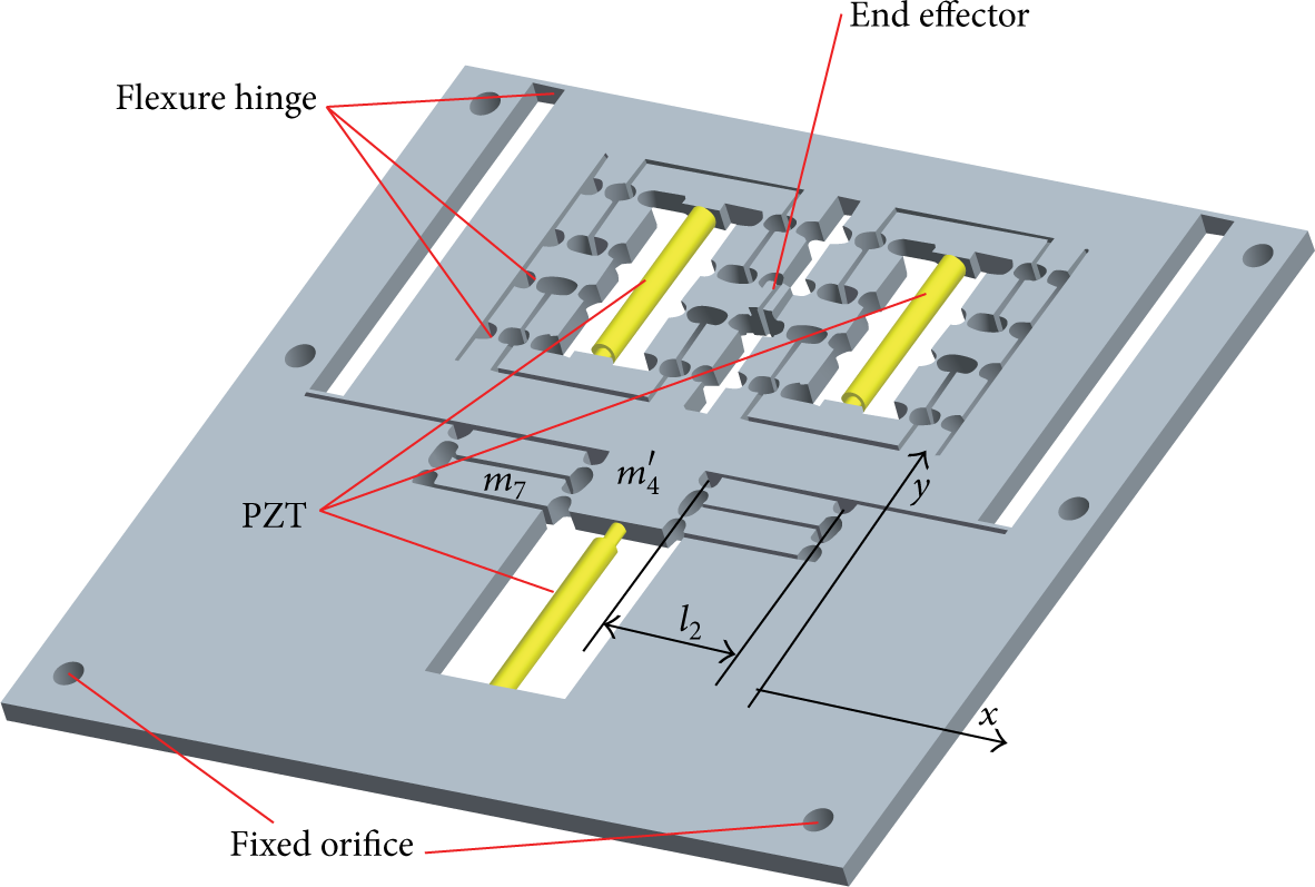
A 3-dimensional structure diagram.
The 3-dimensional structure diagram for the whole microgripper is designed in Figure 3, where it can be observed that the whole stage is symmetric along the y axial direction, and three piezoelectric ceramics actuators whose motions are independent are used, which can achieve the good decoupling effect in the x and y directions.
The size dimension for the whole mechanism is 176 mm × 179 mm; a bigger displacement of 95.90 μm will be produced in the end effector when the input displacement is 20 μm proposed by PZT, which can have more information about analysis of the mechanism using the ANSYS software in the later part.
3. Flexure Based Mechanism Model
3.1. The PRBM (Pseudorigid-Body Model) for Single Bridge Type Amplifier
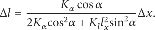
In this paper, the circle notch joint based flexure can be adopted to the single bridge type amplifying mechanism. So the PRBM is established for calculating the amplification ratio, the input stiffness, and the maximum stress, respectively. The microgripper is fully symmetric from Figure 2 and the sole gripper is also entirely symmetric in x and y directions in Figure 1(a). Therefore, a quarter of the single clamp is used to set up the PRBM and is analyzed. The quarter modeling of the whole structure clamping and the situation when it is forced are shown in Figure 4, from which it can be observed that the force Fin is added to the A point and the output force Fout is correspondingly produced. The yellow solid lines express the condition after transformation and the dash lines are the situation before deformation in the PRBM, as shown in Figure 4. The deformation displacement of the A point is Δx, and there is a movement displacement amplified by the single bridge type mechanism Δy in the C point. Otherwise, the angle between the line EF and the horizontal line is α. And the l indicates the length from E point to F point.

The quarter of mechanism forced and PRBM diagram.
3.2. Hinge Model
Two hinges for the microgripper, one is the half circle notch joint and the other one is the rectangle joint, are shown in Figure 5. The former one is purposed to improve the precision and the later one is aimed at using the good deformation for the microgripper, respectively. Their characteristics for stiffness and stress have been analyzed in [16] and the formulas for them are expressed in the following equations. The stiffness and stress for the circle notch are

Joint forms.
3.3. Material and Manufactory
The flexured gripper is to transmit displacement and moment depending on the deformation of the flexured material to make the mechanism move. Generally, the magnetic material is not suitable for flexure mechanisms, while the Aluminum alloy is fitted for them, because it has a bigger deformation. The ratio value (σ s /E) for the yield strength and elasticity modulus of the material should be large as much as possible, which may acquire higher elasticity. The performance for several materials is listed in Table 1. We can observe from the table that the ratio of the yield strength and elasticity modulus of the material Ti-6Al-4V is not only maximal but also has the large density. However, the ratio value of the second material AL7075-T6 is almost the same to the Ti-6Al-4V but its density is the half of Ti-6Al-4V, so its mass is very light. The third material ASTMA541 has not only the small ratio value for the two features but also bigger density than the former materials. Therefore, the material AL7075-T6 is selected as the fabricating material of this microgripper considering its good features from above analyses. The monolithic Aluminum plate will be processed to use the technology of WEDM (Wire Cut Electro Discharge Machining), which can overcome the errors coming from the joint friction. Otherwise, the processing accuracy can reach nanoscale.
Performance comparison for several Aluminum alloys.

4. Modeling Analysis
4.1. Kinematics and Statics
4.1.1. The Amplifying Ratio and Stiffness for the Bridge Type Mechanism
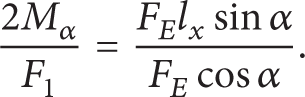
The full symmetry is the main characteristic of the bridge type amplifier. So the kinematics for the single arm will be analyzed [17], which is shown in Figure 4. It can be observed that the force Fin is added to the A point and the output force Fout is correspondingly produced. The angle between the line EF and horizontal line is α. The flexure hinge is regarded as the torsion and linear spring. Kα and K l are the corresponding stiffness, which have been analyzed in [18]. Therefore, the force diagram for the single bridge mechanism is shown in Figure 6. The horizontal symmetric force for the F point in the x direction is derived due to the symmetrical mechanism, so the whole single arm is only suffering a horizontal direction tension force F E in the E point and the torque 2Mα is coming from the two joints. Considering that the input Fin is in the midpoint, the tension force F E is the half of the force Fin. The following equation can be derived according to moment equilibrium relation:

where α and l x are the angle between the EF line and horizontal line as well as the length of the single arm beam, respectively.
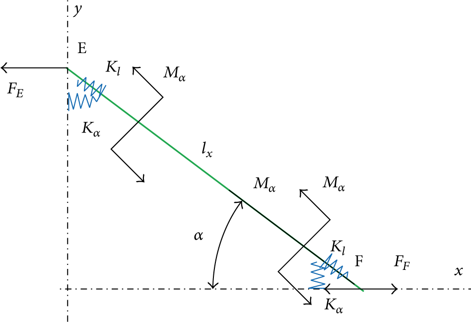
Single arm forced diagram.
The sole arm does not only suffer the bending moment but also produces the tensile deformation caused by the force F E , so the axial force can be expressed along with the axis direction for EF line:

The following equation can be obtained from the formulas (1) and (2):
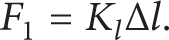
Supposing that the bending deflection is Δα and the elongation value is Δl and considering the equations Mα = KαΔα and F1 = K l Δl at the same time, the formula (3) may be written as follows:

The term 2Δl indicates that the two flexure hinges have the tensile deformation; we can find the ratio of Δα and Δl from (4):

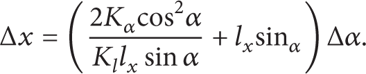
The Δx is the deformation of the single arm in the E point along with the x direction under the force F E , which can be shown in Figure 4 and the energy equation can be expressed by

Substituting (1) and (2) into formula (6), the new equation can be written by

And then, substituting the formula (5) into (7), the relation for the Δx and Δα can be derived as follows:
In addition, output displacement in y direction can be expressed as follows:
So the relation between the micrometric displacement Δy and bending corner Δα in the y direction according to the derivative of the formula (9) can be written by

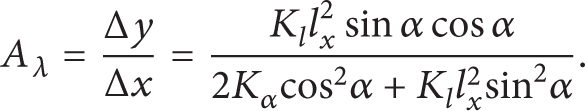
So the amplifying ratio Aλ for the single arm mechanism can be produced by the formulas (10) and (8):
According to the numerator part of (4), the relationship between the F E and Δα can be obtained by

Substituting the formula (12) into (8), we can get the relationship equation for the single arm input and displacement deflection:

Therefore, the above formula can be written as input stiffness Kin:

4.1.2. Stress Analysis
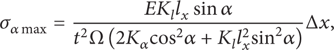
The maximum stress σmax of the material must happen in the weakness of the flexure hinge where it has the thickness of 0.6 mm at the bridge beam flexure hinge. The stress is the sum of the bending deflection and tensile deformation, whose stiffness is Kα and K l , respectively. So we can obtain it as the following equation [19]:
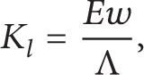
where E is the elastic modulus, Λ = ∫0π(a x sinα/(2a x + t − 2a x sinα))dα, and w is the thick of the whole mechanism.
So the deformation situation in the tensile direction can be obtained by
Substituting (15) into formula (16), the following equilibrium equation can be produced for the tension force:

Therefore, the stress σ lmax generated by the tensile deflection may be expressed as follows:

where E is the elastic modulus, t is the width for the thinnest part, Δl is the deformation displacement in the EF axis direction, and Λ = ∫0π(a x sinα/(2a x + t − 2a x sinα))dα.
For convenience, firstly the relationship can be expressed by Δl and Δα, and then the stress is calculated. So the relationship can be derived from the formulas (8) and (5):

Then substituting (20) into (18), the relationship between the axial maximum stress along with the EF direction and input displacement Δx can be written by

where E is the elastic modulus, t is the width for the thinnest part of hinge, and Λ = ∫0π(a x sinα/(2a x + t − 2a x sinα))dα.
Moreover, the stiffness of torque for the hinge has been given in [19]:

where E is the elastic modulus, w is the thick of the mechanism, and
The torque at the EF can be expressed when the minimal angular displacement Δα occurs in the joint. Consider

Substituting formulas (19) and (22) into (23), the relationship between the torque and input displacement Δx can be derived by

According to the mechanics of materials, the relation between the stress and torque is as follows:

where M z is the torque and I z and y are the inertia moment of the cross section to z axis and the width, respectively.
In this paper, the inertia moment for the thinnest part of the hinge is expressed as I z = wt3/12, considering (24) and (25) at the same time, where the y is expressed by the thinnest width t. So the maximum stress caused by torque can be obtained by
where E and t are the elastic modulus and thinnest width of the joint, respectively, and
Therefore, the total stress value σmax for the thinnest part of the hinge can be expressed by

Substituting the formulas (21) and (26) into (27), the relationship between the maximum stress σmax and input displacement Δx can be derived:

Rearranging the above equation, we can obtain

where E and t are the elastic modulus and the thinnest width of the hinge, respectively,
Therefore, the equations about amplifying ratio (11), input stiffness (14), and the maximum stress (29) for the bridge type amplifying mechanism have been calculated. And the analysis using ANSYS software will be provided and validated by formulas in the later section. The relationship diagram about the input and output displacements is shown in Figure 7 by actual calculating amplifying ratio and FEM (finite element model). The actual calculating amplifying ratio is 7.17, which is bigger than the amplifying ratio of 4.795 when using FEM. And the lost displacement is much more, which is caused by the symmetrical distribution and the hinge itself. But there is a good decoupling characteristic about the whole microgripper from the later FEM analysis.

Comparing between the input and output displacements.
4.2. Dynamics and Natural Frequency
4.2.1. Dynamics of the Mechanism
The microgripper is composed of a parallel four-bar mechanism, which has noninterference in the x and y directions, the minimal motion is produced in the y direction when the single input displacement is in the x direction. At the same time, if there is a sole input displacement in y direction, the output displacement in the x direction would be small. There are displacements ±d x in the x direction when the microgripper is clamping object and the movement d y in the y direction is the action ahead. The quality m and the length l are shown in Figures 2 and 3, respectively. The natural frequency of the microgripper can be calculated by using Lagrange's equation. The variables [d x ,d y ] can be selected as the generalized coordinate, so the kinetic energy T and potential energy V may be calculated, respectively. From Figure 3, we can observe that the three PZTs drive in the same way, but the clamping operation in the x direction comes from the two symmetric PZTs, so the input displacement is d x ′ = d x /Aλ. Then the potential energy V is obtained [17]:
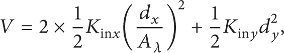
where Kinx, Kiny are the input stiffness in the x and y directions, respectively. And Aλ is the amplifying ratio of the bridge type amplifier.
Because the clamping motion in the x direction is fully symmetric, so the kinetic energy is identical for two arms. The kinetic energy of single beam mechanism can be expressed according to Figure 1(a):

where m R = m5 + m6, m T = m1 + 4m2 + 4m3 + m5 + m6.
Similarly, the kinetic energy of the other arm is obtained by

And in Figure 3, we can obtain the kinetic energy for the input y direction since the whole gripper is actuated by a parallel four-bar mechanism:

where m V = 2m1 + 8m2 + 8m3 + 2m5 + 2m6 + m4′ + m4.
Therefore, the total kinetic energy for the microgripper is derived by
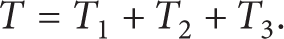
Substituting (31), (32), and (33) into (34), the kinetic energy equation can be expressed as follows:

where Aλ is the amplifying ratio of the bridge type amplifier and m T = m1 + 4m2 + 4m3 + m5 + m6.
4.2.2. Natural Frequency
Lagrange's equation is used to calculate the natural frequency value for the microgripper:
where F
i
(i = 1, 2) expresses the ith driving force, correspondingly, and
Substituting formulas (30) and (35) into (36), the general kinetic equation for the Lagrange can be derived by

where
The particular solution for (37) is the natural frequency, so the particular solution equation can be solved when the F is zero in (37):

Moreover, according to the vibration theory, the eigenvalue and eigenvector can be expressed by the undamped vibration equation:

where λ i , φ i (i = 1,2) are the eigenvalue and eigenvector of (38), and λ i can be derived by the following equation:

According to the knowledge of the vibration theory, the relationship between the natural frequency f i of the mechanism and eigenvalue λ i can be denoted by the following formula:
Therefore, substituting (40) into (41), the natural frequency of the microgripper is obtained by

5. FEM Analysis and Validation
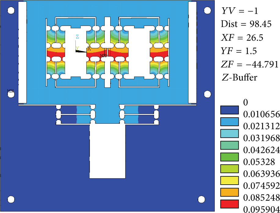
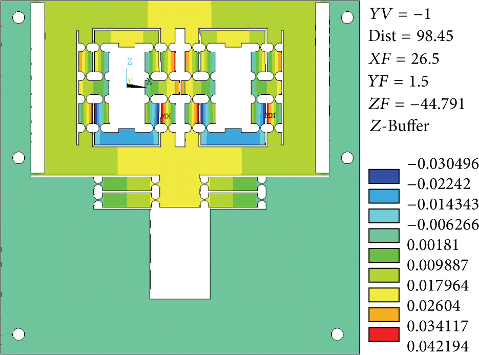
In this section, the ANSYS10.0 software will be adopted to analyze the kinematic characteristics for the novel microgripper. The 20 nodes for the solid 186 will be used for the structure. And the mesh dividing of the structure is shown in Figure 8, the freedom dividing as up to the grade precision 2 is selected. The total displacement deformation situation for the whole mechanism can be shown in Figure 9, when the input displacements are 20 μm in the three PZTs, and the displacement is up to 95.90 μm. The single observed deflections in x and y directions are shown in Figures 10 and 11, respectively. For validating the decoupling of the mechanism, the sole displacement of 20 μm input in y direction can be given, and then looking over the effect in the x direction, the end effector has the minimal displacement deformation in Figure 12, which can be ignored. At the same time, the effect in the y direction coming from another direction inputting is also very small and negligible for calculation as shown in Figure 13. So the mechanism has good decoupling characteristics.

Mesh generation diagram.
x and y direction input.

Displacement change in y direction.
Displacement transformation in x direction.
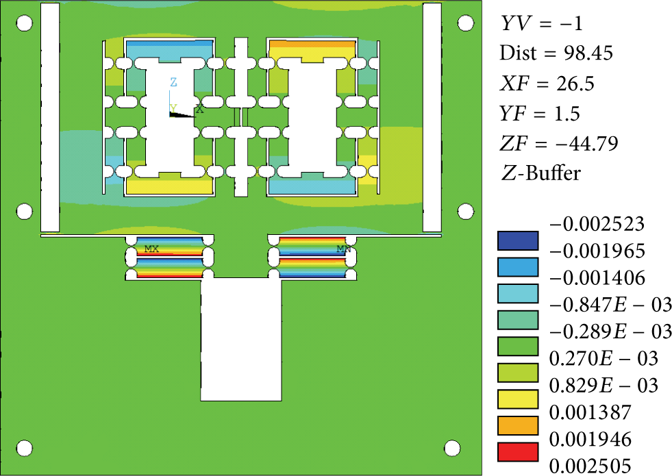
Effect in the x direction for inputting y direction.

Effect in the y direction for inputting x direction.
The HPSt 150 is selected as the actuator for the microgripper, which has the maximum movement of 50 μm. So the maximum occurred when the input displacement is the max, and the stress distribution is shown in Figure 14, in which the max stress of 391.25 Mpa can be observed, and it is smaller than the allowable stress of the material, which occurred for the flexure hinge of the bridge type beam just as the theoretical analysis.

Maximum stress situation for maximum input displacement.
For knowing about the natural frequency condition of the mechanism, the former four orders of modals are analyzed as using the ANSYS software and their diagrams are shown in Figure 15. We can find that the frequencies are not big enough; that is, the stiffness is small or the mass is light.

The distribution of former four order modals.
6. Conclusions
In this paper, a novel full decoupling microgripper is designed and analyzed, which has two directional motions in terms of clamping in the x direction and pushing ahead in the y direction. Furthermore, the amplifying principle of the bridge type mechanism is analyzed through using the PRBM; then, the real amplifying ratio, input stiffness, and maximum stress are calculated. The comparison is made between the output displacement and input displacement according to the calculated amplifying ratio and the amplifying ratio derived from the FEM. The actual calculated amplifying ratio is 7.17, which is bigger than the amplifying ratio of 4.795 obtained by FEM. And the lost displacement is significant, which is caused by the symmetrical distribution and the hinge itself. The two directions are fully independent from the analysis result of the FEM, because the single direction input is not affecting the other direction output. The max stress of 391.25 Mpa, which is less than the allowable stress of the material, is obtained by inputting the maximum displacement for the actuator, and the stress distribution is also shown in Figure 14. Finally, the former four-order modals of the mechanism are produced by using the ANSYS10.0 software, from which it is observed that the frequencies are very small. The advantage of the designed mechanism is that it behaves decoupled feature and a big stroke, in which the full decoupling in x and y directions can be achieved and the maximum displacement is more than 200 μm. The microgripper mechanism will be optimized in our next step of work [20].
Conflict of Interests
The authors declare that there is no conflict of interests regarding the publication of this paper.
Footnotes
Acknowledgments
This work was supported in part by National Natural Science Foundation of China (Grant no. 61128008), Macao Science and Technology Development Fund (Grant no. 108/2012/A3), and Research Committee of University of Macau under Grant nos. MYRG183(Y1-L3) FST11-LYM and MYRG203(Y1-L4)-FST11-LYM).