
Abstract
Concrete displacing boom is large-scale motion manipulator. During the long distance pouring the postures needs to frequently change. This makes the real-time dynamic analysis and health monitoring difficult. Virtual spring-damper method is adopted to establish the equivalent hydraulic actuator model. Besides boom cylinder joint clearance is taken into account. Then transfer matrix method is used to build the multibody concrete placing boom model by dividing the system into two substructures. Next typical working conditions displacements and accelerations during the pouring process are studied. The results of the numerical method are correct and feasible compared with Recurdyn software and the experimental ones. So it provides reference to the real-time monitoring and structure design for such light weight large scale motion manipulators.
1. Introduction
Concrete displacing boom is light weight large movement flexibility manipulator. Until 2013, the longest displacing boom has reached 101 meters. The frequent postures change during pouring process usually leads large vibration. In particular the tip displacement, structure stress and hydraulic actuator force are changing along with different working conditions. So it brings difficulty to boom real-time health monitoring and dynamic analysis. By far the existing researches usually ignore the influence of joint clearance. Besides transfer matrix method has advantages of fast calculation in solving this multibody system dynamics.
The traditional researches on multibody manipulator are as follow. Cazzulani et al. studied the dynamics of a 1: 3 truck mounted concrete pump truck boom. The vibration suppression method is given to this manipulator. The added tip end mass influence on the natural frequency and vibration was also studied [1]. Lenord et al. built an interdisciplinary 4-section boom flexible nonlinear model. Linear and nonlinear characteristic were simulated by damping optimization. Finally a linear substitute model was adopted [2]. Liuet al. used Lagrange method and have built a commercial truck mounted concrete pump boom model. Then tip displacement was analyzed [3]. Heinze established a hydraulic crane boom model and did the trajectory control by considering the boom friction [4].
The studies of joint clearance are as follows. Shabana et al., Bauchau et al., Nachbagauer et al., and Tian et al. did researches on the absolute nodal coordinate method to calculate flexible nonlinear structure with joint clearance [5–8]. Chen et al. have established the nonlinear motion equations of flexible rigid booms with ideal joints [9]. Mukras et al. analyzed a planer flexible linkage joint dynamics and made experimental. They proposed that joint clearance in such mechanism should not be neglected [10, 11]. Flores et al. used the friction impact principle studied on a slider-crank revolution joint clearance characteristic [12].
Based on the traditional transfer matrix, Rui et al. proposed multibody system transfer matrix method in 1993 and have do further research on it in recent years [13]. Due to the high efficiency in modeling and fast in calculating, transfer matrix method is widely used in many mechanical engineering fields. Jiang and Chen, Liu et al., Sun et al., and Zhan et al. used transfer matrix method in multirotor engine natural frequency calculation, one-dimensional structure dynamics analysis and vibration control of multidirection rocket tube [14–18]. Ellakany et al. used transfer matrix on the research of beam free vibration. That proved to be a good tool for such mechanism design [19, 20].
Large-scale motion concrete displacing boom joint clearance is usually ignored in the existing researches. This paper is organized as follow. In Section 1 researches on concrete displacing boom are introduced. In Section 2 of this paper joint clearance and cylinder stiffness are studied by virtual spring damper method. In Section 3 the displacing boom model by transfer matrix method is established. In Section 4 kinematic and dynamic characteristic of four typical postures of the boom systems are compared with Recurdyn software and test results. Finally in Section 5 the conclusions are presented.
2. Joint Clearance and Hydraulic Cylinder Stiffness
Hertz contact model is usually used in contact system, but damping energy loss is not considered in the collision process. In order to take full account of damping effect of joint clearance, Lankarani-Nikravesh contact model [11] is adopted as shown in
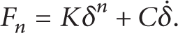
In (1), F
n
is the actual contact force, K is stiffness coefficient between the contact bodies, δ
n
is penetration depth, C is contact damping coefficient, and
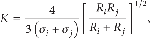


The boom test rig material is Q345B, υ is material Poisson's ratio, and E is Young's modulus. According to [16], n is selected as 1.5. R
i
, R
j
are the radius of contact bodies. c
e
is restitution coefficient which is 0.9 in this model.
Pin and bushing values.

Based on the hydraulic oil and cylinder calculation the stiffness of the four driven cylinders k are, respectively, 40 kN/mm, 30 kN/mm, 20 kN/mm, and 6 kN/mm in this paper.
3. Dynamic Model with Joint Clearance by Transfer Matrix Method
3.1. Mathematical Model
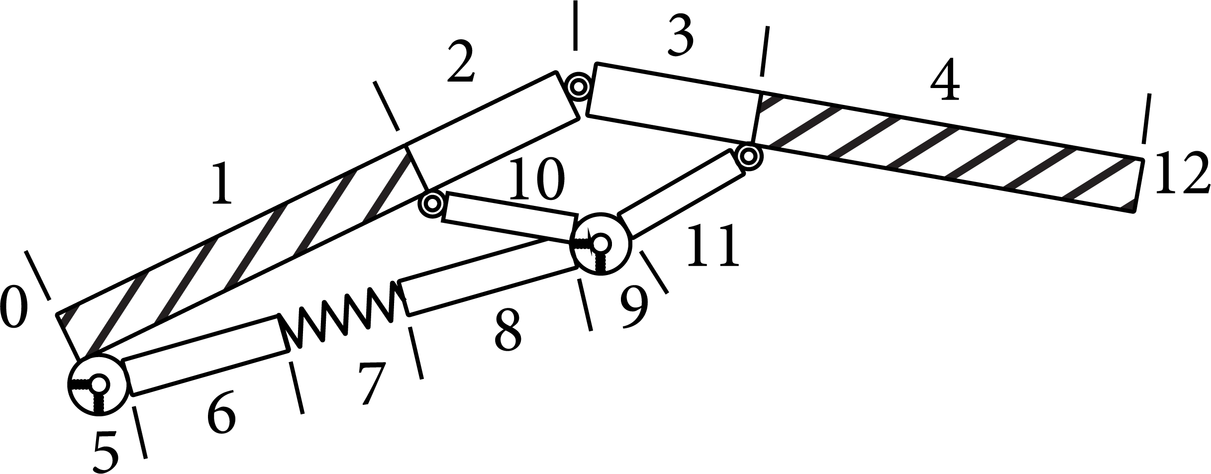
The multibody displacing boom is composed of booms, links, hydraulic actuators, and the base. According to the connection type the system is divided into 2 substructures as in Figure 1. The overall transfer equation and transfer matrix can be obtained by combining substructures A and B.

Topology of mobile concrete pump boom 1: base; 2, 4, and 7: hydraulic actuator; 3, 6, 9, and 12: boom; 5, 8, and 11: link.
Then boundary condition is added in dynamic equation. In the model the booms are equivalent to Euler Bernoulli beam. Hydraulic actuator and piston are equivalent to elastic beam element and the hydraulic oil along with the cylinder is equivalent to spring element with certain stiffness as in chapter 2. The revolution joint clearance is equivalent to spring-damper system. Low operator speed is assumed to neglect the boom centrifugal and Coriolis acceleration influence. Then the state vectors of all the connected points are defined as

In (5) X, Y are linear displacements, Θ z is angular displacement, M z is internal torque, and Q x , Q y are internal forces.
3.2. Substructures A and B Transfer Matrix
Substructure A is composed of the first boom, base, the first hydraulic actuator cylinder, and the corresponding joint clearance (see in Figure 2). Besides sub-structure B includes the other three booms and the corresponding joints and links. Furthermore sub-structure B can be divided into three sections too (see in Figure 3).

Substructure A.
Substructure B.
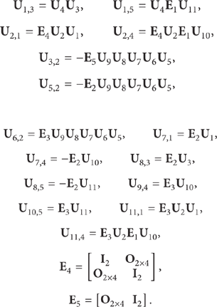
In Figure 2, 0 is defined as sub-structure A input terminal and 8 is output terminal. 1, 3, and 5 are rigid elements and 2, 4, and 6 are planar flexible spring connection element. 6 is joint clearance element and 7 is uniform Euler-Bernoulli beam. All the elements of transfer matrix

The displacement and force between 1, 7, and 6 components can be written as

Equation (8) can be obtained by (6) and (7):
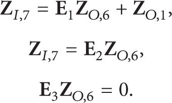
In (8),

Then sub-structure A transfer equations can be written as.

Here in (10) the transfer matrix

In Figure 3, 0 is defined as input terminal and 12 is output terminal of sub-structure B. 2, 3, 6, 8, 10, and 11 are rigid elements. 5, 7, and 9 are planar spring joint elements. 1, 4 are regarded as cross-section Euler-Bernoulli beam. Similar to sub-structure A, the transfer matrix

Here
3.3. Overall Transfer Matrix
As in Figures 2 and 3,


Matrices

The boundary state vector can be obtained from boundary conditions. And the sub-structure A boundary state vector is

Besides the sub-structure B nonterminal component state vector (number as i) is

Meanwhile the sub-structure B terminal component state vector (number as N) is

With the boundary conditions the zero elements (total 21) of

In order to get different working conditions displacements the overall transfer matrix needs to reset only by changing the elements angle because the connection relationships are the same in all postures. The rotation angle of each boom can be set at first; then the angle coordinate transformation matrix can be got by (21). Next the new posture transfer matrix and transfer equation can be calculated. Finally the boom displacements of these postures can be obtained. And θ i (i = 1, 2, 3, 4) is the boom angle relative to horizontal plane in this paper:

Here,
The numerical simulation is done by MATLAB software. The boom test rig parameters values are in Table 2. The preset solvable interval is done by dichotomy which satisfies the tolerance of (20) (tolerance ω is between −1e−7 and 1e−7). Finally the displacements of the four typical postures are got.
Main parameters of each boom.

4. Numerical and Experiment Results
4.1. Typical Posture Angles
According to the typical working conditions the following four postures selected in the simulation and experiment are shown in Figure 4.

Common posture of booms.
Table 3 is each boom horizontal angle of the working conditions.
Different postures boom angles.

The joint clearance between booms and hydraulic actuators is considered during the simulation. Next the displacements are obtained and compared with the results of Recurdyn software as in Figure 5.

Different working conditions displacements.
In Figure 5 the four typical conditions displacements calculated by Recurdyn and transfer matrix method agree very well. The numerical model shows certain flexibility because the joint clearance is equivalent to spring-damper by transfer matrix method. Thus when the motion stops the boom vibration will last for several seconds. Also in the numerical model the boom has downward motion at first because of the gravity influence and then moves upward to the predetermined position driven by the hydraulic actuators. So the four typical working conditions tip displacements by numerical simulation are 0.2 m–0.4 m smaller than Recurdyn software results.
4.2. Experiment and Results
In this section, in order to verify the correctness of numerical simulation an experiment is done on a multibody displacing boom test rig which is 13.46 meters long as shown in Figure 6. The test rig parameters values are in Table 2. The required instruments also include 24-channel dewesoft dynamic data acquisition equipment and several acceleration, strain, and angle sensors. The accelerations of the working conditions compared with the numerical simulation ones are shown in Figure 7.

The boom test rig.

Different working condition accelerations.
From Figure 7 we can see that the acceleration results between the test ones and the numerical ones agree very well too, because the concrete displacing boom is a flexible nonlinear system. And it has large vibration when the motion stops. As to numerical model the only flexible component is joint clearance. So it can be seen that the test values are larger than those of numerical results.
5. Conclusion
Transfer matrix method is presented to establish a multibody large scale boom dynamic model in this paper. The model is divided into 2 sub-structures. Sub-structure A is boom 1 and the base. Sub-structure B is the other three booms and cylinders. The two sub-structures in the model are connected by their transfer matrices. Meanwhile the joint clearance between the booms and driven cylinders is taken into account. Lankarani-Nikravesh contact is considered too. Besides the hydraulic cylinders are equivalent to spring damper system.
Four typical working postures are studied then. By comparing the displacements of the four working conditions between numerical simulation and Recurdyn software, we can draw the conclusion that the tip displacement agrees well with them. The largest error is about 150 mm occurring in the horizontal condition. This is because this is the most dangerous condition and the flexible influence to the displacement is the largest of all.
Next the boom tip accelerations of the four conditions are carried out on a test rig. The numerical and experimental results agree well too. The largest acceleration is about 20 m/s2. So the model in the paper is correct and reasonable when considering joints clearance. And the transfer matrix method has the advantages of fast modeling and posture transforming for such mechanisms. It is suitable for dynamics analysis and real-time monitoring during the working process. The results can be applied to structure design for engineers of these multibody manipulators.
Conflict of Interests
The authors declare that there is no conflict of interests regarding the publication of this paper.
Footnotes
Acknowledgments
This work was supported by State Key Laboratory of High Performance Complex Manufacturing (no. zzyjkt 2013-0613), Central South University, the National “863” project (no. 2008AA042801) and National Basic Research Program “973” program (no. 2010CB731703 and 2012CB619505).