
Abstract
For the image-guided surgery, the positioning of mobile C-arms is a key technique to take X-ray images in a desired pose for the confirmation of current surgical outcome. Unfortunately, surgeons and patient often suffer the radiation exposure due to the repeated imaging when the X-ray image is of poor quality or not captured at a good projection view. In this paper, a virtual reality (VR) aided positioning method for the mobile C-arm is proposed by the alignment of 3D surface model of region of interest and preoperative anatomy, so that a reference pose of the mobile C-arm with respect to the inside anatomy can be figured out from outside view. It allows a one-time imaging from the outside view to greatly reduce the additional radiation exposure. To control the mobile C-arm to the desired pose, the mobile C-arm is modeled as a robotic arm with a movable base. Experiments were conducted to evaluate the accuracy of appearance model and precision of mobile C-arm positioning. The appearance model was reconstructed with the average error of 2.16 mm. One-time imaging of mobile C-arm was achieved, and new modeling of mobile C-arm with 8 DoFs enlarges the working space in the operating room.
1. Introduction
Image-guided surgery (IGS) is a minimally invasive procedure by making small incisions on patient's body [1]. In IGS, preoperative CT data and intraoperative X-ray images are widely used for the intervention guidance. Preoperative data is used for diagnosis and surgical planning, and X-ray images are captured to verify the surgical outcome. Figure 1 shows an exemplar scenario in IGS. The mobile C-arm is one of the most essential tools for X-ray imaging in the congested operating room due to its compact and versatile structure. During the operation, X-ray images cannot be captured continuously due to the radiation exposure. To reduce it, the mobile C-arm needs to be positioned in a proper pose at distinct points of operation. Accurate positioning technique of mobile C-arm is required in surgical applications, for example, percutaneous needle procedures and fracture fixation with locking screws and nails. In such cases, the C-arm needs to be piloted to the needle progression view and entry point view to confirm the current pose of the needle [2] or over the nail so that each screw hole appears as a perfect circle [3]. Therefore, mobile C-arm positioning is a routine surgical task and has become more important for the intraoperative imaging techniques [4].

Exemplar scenario in image-guided surgery.
It is a great challenge to properly align the mobile C-arm to the hidden region of interest (ROI), especially for corpulent bodies. Currently, the positioning of mobile C-arm extensively depends on the surgeon's experience, as the ROI is in the hidden anatomy, and there is no appearance information as the reference. Surgeons can easily identify the ROI in the CT data, but it is difficult to figure out the pose of mobile C-arm relative to the appearance of patient in image-guided surgery. Although the surgeon makes several marks on the patient's skin for the self-explaining using preoperative CT data, X-ray images have to be captured repeatedly for the image quality and projection view in practice. This increases the additional radiation exposure to the patient and surgeons and prolongs the procedure of the whole operation.
Additionally, it is difficult to operate the mobile C-arm manually due to the complicated rotational and linear movements of C-arm. To facilitate the operation of mobile C-arm, it is usually modeled as a manipulator with five or six degrees of freedom (DoFs) in the literatures, for example, robotized C-arm system with 5 DoFs [5, 6] and 6-DoF C-arm system integrating the operating table [4]. However, considering the limit of each DoF, mobile C-arm with current modeling cannot reach an arbitrary pose in 3D Cartesian space. And the determination of the target pose of mobile C-arm is not discussed and defined explicitly in the literatures.
The objective of this paper is to determine a reference pose relative to the patient's appearance and achieve one-time imaging using mobile C-arm. To this end, a virtual reality (VR) aided mobile C-arm positioning method is proposed. Figure 2 illustrates the configuration of proposed method. In VR, an appearance model of patient and preoperative CT data are aligned, so that a reference pose is determined in regard to the appearance. The appearance model is reconstructed by a single camera mounted on the mobile C-arm. To facilitate the control of mobile C-arm to the reference pose, the mobile C-arm is modeled as a mobile manipulator. The movements of mobile C-arm and camera are tracked by Vicon motion tracking system referred to as Vicon for simplicity in the remainder of this paper. The main contributions of this paper are described as follows.
A camera augmented mobile C-arm system is proposed to determine a reference pose relative to the appearance of patient. The novel configuration allows the seamless integration into surgical workflow.
The mobile C-arm is maneuvered by modeling C-arm as a mobile manipulator.

Configuration of virtual reality aided mobile C-arm positioning.
The remainder of this paper is organized as follows. Section 2 introduces the required materials in the configuration of proposed method. In Section 3, VR aided determination of the reference pose is discussed, including system calibration and the derivation of reference pose with respect to the appearance of patient. The kinematic model and control of C-arm are presented in Section 4. Section 5 shows the experimental results using a public golden standard dataset and spinal phantom. Related work is summarized in Section 6. Section 7 concludes this paper.
2. Materials
To determine a reference pose relative to the appearance of patient, the mobile C-arm is augmented by mounting a single camera on its gantry next to the X-ray source. An appearance model of patient can be reconstructed from images recorded by the camera. Then, the appearance model and preoperative CT data are aligned in virtual reality to find the reference pose, since the region of interest may be identified in preoperative data. To achieve the reference pose, the mobile C-arm is controlled as a mobile manipulator consisting of a mobile base and a robot manipulator with five DoFs (A3–A7). The mobile base has additional three DoFs, including both translations (A0 and A1) in the transverse plane and rotation against the gravity direction (A2).
In this paper, a mobile C-arm, single camera, Vicon motion tracking system, and spinal phantom are used. The camera is mounted on mobile C-arm to capture the appearance information of patient, which acts as a reference for mobile C-arm positioning. Because the mobile C-arm is modeled with 8 DoFs to facilitate the operation of C-arm, and it is not motorized yet, Vicon is employed to track the movements of joints on mobile C-arm. A spinal phantom was chosen in experiments to verify the performance of proposed method.
2.1. Camera Augmented Mobile C-Arm
ARCADIS Varic (Siemens, Germany) is used as an advanced multipurpose mobile C-arm. It enables 1 K2 X-ray image. The mobile C-arm is usually modeled as a manipulator with 5 degrees of freedom, including vertical, swivel, horizontal, angular, and orbital movement of the image intensifier. Detailed illustration can be found in [7]. In order to track the mobile C-arm, Vicon is employed, and several infrared (IR) reflective markers are attached on the C-arm. These markers can be used to determine the increment of each joint, the position of C-arm base, and the pose of X-ray source. The tracking system will be introduced later.
The mobile C-arm is augmented with Guppy Pro F-201C from AVT Inc., Germany. This camera provides high-quality images with the resolution of 2 megapixels (1624 × 1234). The camera was also tracked by Vicon to reconstruct an appearance model with the physical size.
2.2. Vicon Motion Tracking System
Vicon motion tracking system (Vicon Inc., UK) consists of Vicon T-Series cameras that are the world's next generation motion capture devices. Each camera provides a 16-megapixel resolution (4704 × 3456) at the frame rate of 120 fps. The tracking system works with IR reflective markers that are different size of small plastic balls covered with reflective tape from 3M Inc., US. When the infrared is projected to the surface of markers, the light with the same wavelength returns to the camera, so that each camera can get the 2D position of markers; then, the 3D position can be obtained with submillimeter accuracy by the controller of Vicon. Proper size of makers is chosen in practice, according to the requirement of applications. The diameter of makers used in our experiments is 14 mm.
2.3. Spinal Phantom
The spinal phantom (3B Scientific Inc., Germany) offers an illustration of lumbar vertebrae from L1 to L5 with intervertebral discs. The finest bone structures are accurately depicted. The model can be disassembled into vertebrae and intervertebral discs. To fix the spine, the model is fixed in the pearl cotton, as shown in Figure 3. Eleven IR reflective markers are attached to facilitate the process of calibration between the Vicon and the preoperative CT data. The CT data is collected by a CT scanner (Aquilion ONE, Toshiba, Japan) with a 320-row detector. The resolution of each slice is 512 × 512 pixels, and there are 227 slices in total. The CT volume covers the region of 0.559 × 0.559 mm with a 1 mm slice thickness.

Spinal phantom with IR markers in the experiment.
3. VR Aided Determination of Reference Pose
In this section, the reference pose of mobile C-arm relative to the appearance is figured out based on VR. An appearance model is firstly reconstructed using the camera on mobile C-arm. Then, the appearance model and preoperative CT data are aligned in coordinate system of Vicon. Procedures above need to be implemented only once at the beginning of operation. Since the region of interest can be found in CT data, a reference pose in regard to appearance can be determined using an optimal procedure.
3.1. Reconstruction of Appearance Model
Along with the rotation of mobile C-arm, several images are taken by the camera at different positions, as shown in Figure 4. Orientations of camera are converged to the target. To reconstruct the 3D model, approaches of Structure from Motion (SfM [8]) and Multi-view Stereo (MVS [9]) are employed in this paper.

Reconstruction of appearance model.
Some principles have to be considered during the image collection for SfM-MVS reconstruction. Static scene is required as the reconstruction works by matching the features from different images. Another factor is the illumination condition; strong shadows should be avoided. The reconstruction of patient or ROI totally meets above requirements in the operation room. During the operation, the patient is static due to the anesthesia, and there are no strong shadows when using the surgical shadowless lamp.
In this paper, a sparse point cloud is firstly produced based on a SfM application Bundler [8]. SIFT features are extracted from all images; then, the most prominent features are matched in other images. The 3D coordinates can be computed based on the feature pairs. The resulting point cloud only represents the positions of limited amount of features. To enhance the previous model, Clustering Views for Multi-view Stereo (CMVS [10]) is used for a dense 3D model. It uses the output of Bundler to decompose the input images into a set of clusters. A patch-based MVS algorithm (PMVS [11]) can be used to process each cluster independently and in parallel. This process can efficiently filter out the noise from the SfM process and increase the number of reconstructed points. Nevertheless, the resulting model lacks the scale information compared with the physical object. To this end, the positions of camera are tracked by Vicon during the image collection.
3.2. Calibration of Appearance Model and Preoperative CT
In this paper, the appearance model and preoperative CT data are calibrated in Vicon's frame, as shown in Figure 5. Since the camera is tracked by Vicon, the appearance model can be transformed to Vicon's frame easily. To transform preoperative data to a common coordinate system, intensity-based 2D/3D registration is carried out using 2D X-ray images, which are captured at the beginning of operation.

Calibration between appearance model and preoperative CT data.
In 2D/3D registration, we build a virtual scene identical to actual setting, including focal point (X-ray source) and image plane, as shown in Figure 6. By applying the transformation to preoperative CT, we can generate a floating image by casting rays through CT. The value of each pixel is the summation of intensities along the projection ray. Given the pose of focal point and image plane in Vicon's frame, the transformation of CT data is obtained in Vicon's frame by optimizing the similarity between X-ray image and floating image.
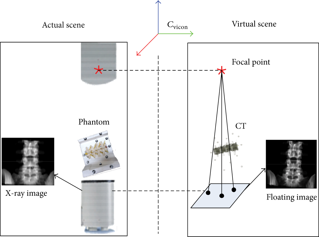
Transformation of preoperative CT data.
3.3. Reference Pose Optimization of Mobile C-Arm
The reference pose of mobile C-arm relative to the ROI in preoperative CT is determined firstly. Since the appearance model and CT data are aligned, we can get the reference pose in regard to the appearance. A vector [x,y,z,α,β,γ] is defined to denote the pose of mobile C-arm, including the position of X-ray source and orientations between central X-ray beam and axes of the coordinate frame of Vicon, as shown in Figure 7. There are infinite solutions for the reference pose. In this paper, the reference pose is optimized by the image quality and radiation exposure. According to as-low-as-reasonably-achievable (ALARA) principle [12], the patient is placed as close to image intensifier and as far from X-ray tube as possible. Because maximum scatter reflects from the side of the patient that is closest to the X-ray source, the beam is directed through the patient at a perpendicular angle to reduce the radiation dose due to the increased tissue thickness. Additionally, the surgeons sometimes have to operate the instrument to finish the specific surgical tasks near the X-ray beam. This is unavoidable to suffer the radiation exposure. Thus, the positions of surgeons’ hands are considered during the determination of the reference pose to enable the hands far from the X-ray cone.

Definition of reference pose.
The X-ray beam is modeled as a cone with the convex at the X-ray source, and the directrix which is the outer edge of the imaging plane of the mobile C-arm. After the surgeon specifies the region to be captured, including the position and orientation, the X-ray source of mobile C-arm should be moved to a desired pose (x,y,z,α,β,γ). The optimal pose of mobile C-arm is determined by considering the image quality, X-ray cone, and position of surgeon's hand. The detailed procedure is described in Algorithm 1.

Calculate the optimal pose of X-ray source.
Firstly, the normal across the center of specific ROI

where (x
c
,y
c
,z
c
) and (x0,y0,z0) are the center of circle and the vertex of cone, respectively.
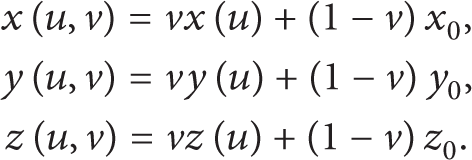

Illustration of two modes for determining the optimal C-arm pose.
As a matter of experience, we can obtain the high-quality X-ray image in the range of [near, far], which is the distance from ROI to X-ray source. The optimal reference pose can be found in [near, far] by applying two modes, that is, translation and rotation mode, as shown in Figure 8. In translation mode, the X-ray source moves along axis of X-ray beam to find the best pose by maximizing the distance from the hand's position H to intersecting point M. If there is no candidate in translation mode, the rotation mode is triggered, where the X-ray source moves around a circle with the origin at ROI center and radius measured from position of X-ray source to ROI center and at the beginning, the X-ray source is positioned to the far point and the axis of X-ray beam is coincident with the normal of ROI. Subsequently, two modes alternately run to minimize the cost function

where
4. Kinematic Modeling and Control of the Mobile C-Arm
To define a unique pose of the image intensifier, it requires six independent parameters resulting in a homogeneous matrix. Obviously, current configuration cannot guarantee an arbitrary target pose to be reached. Moreover, considering the congested operating room, several obstacles need to be avoided to obtain the desired the projection. Therefore, the mobile C-arm is modeled as a redundant robot with three more degrees of freedom assigned to the mobile base, so that the pose of image intensifier is optimized to satisfy the requirements of image quality and radiation doses reduction considering the current position of the surgeon's hands, ROI, and cone of the image intensifier. In this paper, ARCADIS Varic introduced by Siemens Medical Solutions is used. Although this specific C-arm is studied in following sections, kinematic principles can be easily applied to other C-arms due to the similar structure.
4.1. Forward Kinematics of Mobile C-Arm
A kinematic chain is modeled for C-arms as a mobile manipulator to define the relation between the joints and the pose of the X-ray source. To model the mobile C-arm accurately, coordinate origins have to be identified firstly. Specifically, the origin of orbital joint cannot be found on the body of C-arm, while remaining movements can be determined easily. To this end, multiple infrared reflective markers are amounted on the X-ray tube, as shown in Figure 11, and Vicon is employed to collect the 3D information of markers during the orbital rotation. To simplify the fitting procedure, we place the C-arm along the X-axis to make sure the C-arm is rotation in the X-Z plane, when the X-ray source is directly above the image intensifier. Assume the trajectory is an ellipse, and the direct least squares fitting [14] is implemented. The ellipse can be represented in conic form, as expressed as follows:

Figure 9 illustrates that the trajectory is an ellipse with 656.4270 mm for major axis and 655.3992 mm for minor axis. It is an approximate circle, so that we can use the center of circle as the origin of orbital joint.

Ellipses fitting of the orbital movement.
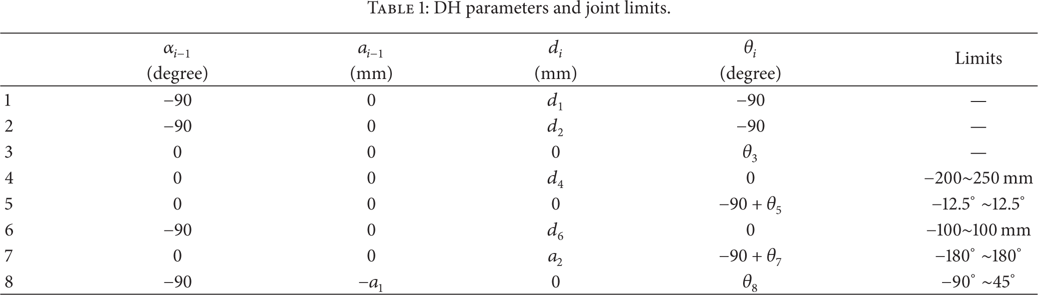
Vicon is used to measure the length of links, especially a1, a2, a3, and a4. a1 denotes the distance between the origins of defined horizontal and angular movement, and a2 is the distance from the origin of angular movement to orbital origin. a3 and a4 are used to define the relation between the orbital joint and X-ray source as the end effector, where a3 represents the distance from origin of orbital joint to the center of X-ray beam and a4 is the distance between the center of X-ray beam and origin of end effector. Following the Denavit-Hartenberg (DH) rules [15], a set of coordinate systems are assigned to each joint, as shown in Figure 10. The origin of the coordinate frame 0 is assigned on the C-arm base as the world frame. O1,O2,O3 are defined as origins of the additional joints. Remaining frames 4~8 are same with the standard modeling. O e is the origin of the X-ray source. Here, a1 = 1160.8982 mm, a2 = 102.9889 mm. Because a2 > 0, ARCADIS Varic is a nonisocentric mobile C-arm.

Kinematic chain of C-arm model with a moving basement.

IR markers on the source of mobile C-Arm.
The corresponding joint parameters and limits are shown in Table 1. A vector q = [d1,d2,θ3,d4,θ5,d6,θ7,θ8] is defined to represent the C-arm joint variables. Let 1T8(q) represent the transformation from the orbital joint to the C-arm base, which can be written by

where
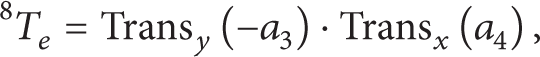
where Trans
y
(a) ∈ R4 × 4 represents the translation along Y-axis with the increment of a. Then, the relation between the X-ray source and world frame can be defined by
DH parameters and joint limits.
4.2. Inverse Kinematics with Base Movement Control
Given a reference pose of the mobile C-arm, the joint variables can be obtained by solving the inverse kinematics problem. In this section, two cases are considered: (1) the base of mobile C-arm is fixed; (2) the base of mobile C-arm is movable. In this paper, the mobile C-arm is not motorized, yet surgeon operates it directly under the guide of Vicon. Several IR markers tracked by Vicon are attached on the C-arm body to monitor the source pose, base movement, and joint increments. Figure 11 shows the markers on the X-ray source to determine the coordinate system of the end-effector. The middle point of the line S1S2 is the origin of frame. Z-axis points to point S2 along the line S1S2, and X-axis parallels the vector
4.2.1. Base of Mobile C-Arm Is Fixed
The mobile C-arm becomes a manipulator with 5 DoFs, when three DoFs on the base are lost. In the 3D Cartesian space, given a reference pose, an analytic solution can be obtained for each joint. Then, we can adjust each joint of mobile C-arm to achieve the reference pose using Vicon for guidance. In this case, please note that the working space of mobile C-arm is limited around the surgical table.
4.2.2. Base of Mobile C-Arm Is Movable
To enlarge the working space, the mobile C-arm is modeled as a redundant manipulator with a movable base. In this paper, the closed-loop inverse kinematics (CLIK) algorithm [16] is used, and the general solution of inverse kinematic is employed based on pseudoinverse Jacobian [17] to minimize the norm joint velocities and avoid the kinematic singularities. As a redundant manipulator for the mobile C-arm, the redundancy is solved using the gradient projection method (GPM) [18]. Thus, the CLIK algorithm with the proportional-derivative (PD) feedback can be expressed as follows:

where x d and x are the desired pose and current pose of X-ray source, respectively. K p is a symmetric positive matrix to guarantee the error converges to zero. h(q) is a scalar cost function, which can be optimized to solve the redundancy based on GPM. In addition, the joint limit avoidance is considered for the local optimization and defined by

Once the joint variables are determined, the base of C-arm is moved first; then, the remaining joints are operated, and eventually the X-ray source reaches the target.
5. Experimental Results and Discussions
The experimental system was set up in Shenyang Institute of Automation, Chinese Academy of Sciences, China. The mobile C-arm was redesigned using several IR reflective markers on the X-ray source, base, swivel link, and corresponding joints, so that the whole C-arm can be tracked using Vicon. Note that a part of markers are used in common during the tracking, for example, vertical, swivel, and horizontal movements. Vicon is fixed on the ceiling of the room in order to track the movement of mobile C-arm, as illustrated in Figure 12. The orientation of Vicon cameras must be adjusted to make sure each IR marker can be seen at any time by three cameras at least for the stable measurement. During the adjustment of tracking system, sometimes the marker on the X-ray source is out of the field of view when the mobile C-arm is rotated along the orbital joint, especially. The spinal phantom attached makers are placed on the table.

Experimental setup.
In this section, the accuracy of appearance model reconstructed by the camera was estimated firstly. A simulation was performed to present the procedure of reference pose determination. To demonstrate the accuracy of virtual reality aided mobile C-arm positioning, the similarity between the floating image and X-ray image was measured. All computations in the experiments were performed on the powerful Lenovo ThinkStation D20, which is assembled with Intel Xeon Processor X5650, 12 G memory, and NVIDIA Quadro 600 graphics card.
5.1. Accuracy of Appearance Model
Figure 13(a) shows the result of reconstruction based on multiview stereo technique. Markers are labeled with Mi, i = 1, 2, …, 11, as shown in Figure 13(b). To measure the accuracy of appearance model, the relative distances from M1 to the rest of markers were calculated. Markers were tracked by Vicon as the ground truth. Figure 14 shows the accuracy of appearance model. The average error of reconstruction is 2.16 mm. An accurate model was reconstructed using a single camera in this experiment.
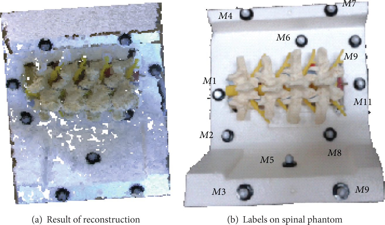
Appearance model.

Accuracy of reconstruction.
5.2. Simulation of Reference Pose Determination
The simulation of reference pose estimation is performed using Matlab. In the simulation, besides the ALARA principle, the minimal distance between the hand (H) and X-ray beam is taken into account. Figures 15 and 16 show the translation and rotation of X-ray cone to reach the optimal pose, respectively. The cone represents the X-ray beam; the vertex of cone is the X-ray source. When the hand is out of the cone, the translation mode is firstly triggered, and the X-ray source moves along the normal direction of ROI. Otherwise, if the hand is always involved in the X-ray beam in the translation mode, the cone will be rotated around the center of ROI in the plane determined by hand and axis of X-ray beam. The maximal rotational shift is set to 10° in the simulation. The rotation mode is usually skipped in practice when the reference pose is found in the translation mode.

Translation mode for determining the optimal C-arm pose.

Rotation mode for determining the optimal C-arm pose.
5.3. Precision of Mobile C-Arm Positioning
Before the actual X-ray image capture, a floating image was generated to make sure the image is desired. To evaluate the precision of mobile C-arm positioning, the similarity between floating image and X-ray image was compared by employing correlation coefficient (CC) as the similarity metric. In this experiment, given a reference pose, the mobile C-arm was positioned using three different settings: (1) manual positioning without inverse kinematic control; (2) inverse kinematic control with 5 DoFs (base is fixed); (3) inverse kinematic control with 8 DoFs.
Figure 17 shows the result of similarity with three settings. When the similarity is equal to 1, the floating image is identical to the corresponding X-ray image. All X-ray images are captured using one-time imaging. Using setting 1, the resulting similarity is lower than the measures in the last two settings. Because it extensively depends on the experience of surgeons in setting 1, the similarity measure is also not stable. Compared with the result in setting 1, the average similarity measures using setting 2 and setting 3 are similar with higher accuracy. It indicates that the inverse kinematic control improves the precision of mobile C-arm positioning. In setting 2, the base of mobile C-arm was fixed next to the spinal phantom. Five-DoF modeling is enough to position the mobile C-arm in the reference pose. In setting 3, inverse kinematic control with 8 DoFs allows the positioning of mobile C-arm from anywhere in the tracking volume of Vicon, since the movements of mobile C-arm were tracked by Vicon. Eight-DoF modeling enlarges the working space of C-arm with the high precision.

Precision of mobile C-arm positioning.
6. Related Work
Some solutions and systems with different configurations are developed to position mobile C-arms precisely for capturing the fluoroscopic image with less additional radiation doses to the patient and operation time. But, there is less work reporting methods in regard to the determination of C-arm pose with respect to the patient.
In [19, 20], camera-augmented mobile C-arm (CAMC) is configured to track the source pose by the onboard camera based on the visible markers amounted on the patient's skin. And an interactive 3D model of C-arm is used in the guidance system. However, only C-arm model cannot provide an unambiguous operation for the surgical staff in the OR without considering the congested ORs with several surgical objects, such as clinical table, moving carts for instruments. Therefore, a complete interface needs to be provided to interact with surgeons. Wang et al. [4] present a modeling method which integrates both the mobile C-arm and patient's table as a kinematic chain without constraining table position. That in turn means the base of C-arm can be translated along the table as the sixth DoF. However, considering the joint restrictions and the self-rotation of C-arm, more degrees of freedom are required to enable the larger working space in the operation room. Without the use of markers or other prior assumptions, Schaller et al. [21] use a time-of-flight (ToF) sensor to achieve inverse C-arm positioning for interventional procedures and mainly focus on the identification of anatomical regions on the patient body to figure out the pose of C-arm. But, fewer details on the repositioning procedure are talked about. In [5], a robotized C-arm is equipped with encoders and motors for each joint, which enables the automatic inverse kinematics. And a closed-form solution for the inverse kinematics has been found for automated C-arm positioning [6]. However, it only provides a unique solution for the C-arm joints according to the position and orientation of the X-ray beam, not accounting for the obstacle collision situations. For configurations above, all joints have mechanical limitations that dramatically restrict the working space at a desired pose to acquire fluoroscopic images. Therefore, additional DoFs are necessary to increase the working space and the possibility of avoiding obstacles.
When the positioning of mobile C-arms performs, a tracking approach has to be implemented to guide the increment of each joint and check if the X-ray source reaches the target. Traditionally, C-arm pose tracking is divided into two categories. One method is external tracking using one or more optical cameras to recover the pose. Navab et al. [19] calculated the C-arm's pose and its required displacement for positioning using the CAMC's optical camera based on additional visible markers on patient's skin. However, C-arm becomes cumbersome with a camera and mirrors attached, while it itself is unstable, when the C bracket is rotating especially. In [22], Ladikos et al. proposed a real-time 3D reconstruction system using 16 optical cameras mounted on the ceiling of the interventional room for interventional environments. It can track the objects and predict collisions by building a 3D representation of all the objects in the room, increase the operating safety, and allow faster device operation. The total system cost is high, and cost-effective devices have to be found.
The other category is achieved by sensors, such as accelerometer and laser. Grzeda and Fichtinger [23] used tilt sensing accelerometers for rotational encoding of C-arm to track the C-arm primary and secondary angle (angular and orbital) rotations during the surgery. For comparison, a webcam is used to obtain ground-truth C-arm poses. A C-arm laser positioning device is developed to facilitate percutaneous renal access [24]. The sensor is attached to the side of the image intensifier of the C-arm. The aiming beam projects a parallax-free crosshair onto the patient's skin along the beam direction of mobile C-arm. That allows the radiology technician to correctly position the C-arm with the minimally unnecessary radiation exposure. However, such methods only track the position of X-ray tube/image intensifier, while the joint status and base movement are also important during the C-arm positioning. For C-arm positioning, we need to know the pose of C-arm. But, previous methods are only concerned about the target position. Therefore, the practical tracking system should track the pose of whole body of the mobile C-arm.
7. Conclusion
In this paper, a virtual reality aided mobile C-arm positioning approach is proposed to reduce the unnecessary radiation dose to the patient and surgeons. The mobile C-arm is augmented in two ways to improve the precision of C-arm operation: (1) a camera is attached to the mobile C-arm to provide the outside information of patient; (2) the C-arm is modeled as an 8-DoF manipulator with a mobile base. During the mobile C-arm positioning, the surgeon can check the joint movements naturally from the outside view without self-explaining requirement. Experimental results showed that 8-DoF configuration enables a larger working space than the standard modeling. The proposed system definitely facilitates and speeds up interventional procedures. In the future, the proposed system will be performed on the animals, and the complex structure of bones, such as deformable spine, will be considered. Besides, the current positioning system will be optimized further to reach the higher requirement in a cluttered environment.
Conflict of Interests
The authors declare that there is no conflict of interests regarding the publication of this paper.
Footnotes
Acknowledgment
This work was supported by Scientific Research Base Project of Beijing Municipal Commission of Education (TJSHG201310028014).