
Abstract
In smart grid, standardized control networks are typical safety critical components which are under the environments with strong noise and interferences. This paper focuses on the safety mechanisms of standardized control networks in smart grid. The underlying safety mechanisms of standardized wired control networks are analyzed deeply. More importantly, there are very few works considering the safety extensions for wireless control networks. To address this, we propose a combined cyclic redundancy check (CRC) based safety extension mechanism. In addition, key points and open issues of safety-related mechanisms are discussed. To evaluate the safety of the proposed combined CRC mechanism for wireless control networks, error correction capability simulation is performed, which validates the effectiveness of the proposed scheme under the typical noisy background in smart grid. The result supports the usefulness and feasibility of our scheme. To the best of our knowledge, this work is the first to focus deeply on the safety mechanisms for standardized control network in smart grid, especially for the safety extension scheme for wireless control networks.
1. Introduction
The critical role of smart grid has already been recognized by worldwide governments and industrial organizations. Depending on the type and purpose of the smart grid, its components are distributed on a local, wide-area, or even global scale. In smart grid, control networks, which can perform communication links and facilities, are an important element of such supervisory control and data acquisition (SCADA) systems. Safety [1–7] is one of the key concerns for these standardized wired and wireless control networks in smart grid. Although many existing works studied security technologies of control networks, there are few works focusing on safety mechanism of them. However, safety and security are different topics. Safety is protection against random incidents which are unwanted, but security is protection against intended incidents which happen due to a result of deliberate and planned act.
There are a lot of control network standards for smart grid which have been developed in parallel by different organizations. Therefore, it is necessary to analyze and enhance the safety mechanisms of these standards. On one hand, there are many communication standards and their safety extension version for wired control networks for smart grid. Here we give the typical standards of wired control networks. (1) PROFIsafe is one of four safety protocols described in the IEC 61784-3 standard [8], which is an extension of the Profibus and PROFINET system. (2) The common industrial protocol (CIP) is an industrial protocol for industrial automation applications [9], which is used in EtherNet/IP, DeviceNet, CompoNet, and ControlNet. (3) CC-Link is the high-speed field network which is able to simultaneously handle both control and information data [10]. CC-Link Safety is compatible with standard CC-Link. (4) Ethernet Powerlink [11] is a deterministic real-time protocol for standard Ethernet and its safety version is Powerlink Safety. (6) EtherCAT is the open real-time Ethernet network originally developed by Beckhoff [12], based on EtherCAT; TwinSAFE [13] from Beckhoff provides a consistent hardware and software technology for achieving integrated and simplified utilization.
On the other hand, some wireless communication standards are proposed for smart grid. The process automation and manufacturing industries are now faced with two independent and competing standards specifically designed for wireless field instruments [14], which are (1) WirelessHART [15] proposed by Highway Addressable Remote Transducer (HART) Communication Foundation (HCF) and (2) ISA100.11a [16] developed by International Society of Automation (ISA). In April 2010, WirelessHART was approved by the International Electrotechnical Commission (IEC) unanimously, making it the first wireless international standard as IEC 62591 [17].
Although there are some safety versions of the wired standardized, it is very necessary to analyze and compare their underlying safety mechanisms to get the advantages and disadvantages of each standard from the view of safety. More importantly, there is no existing safety extension for wireless control networks, which is very important for protection wireless control networks against random incidents which are unwanted. In this paper, we analyze the safety technologies in the existing wired control networks and propose a novel safety extension scheme for wireless control networks in smart grid. To the best of our knowledge, this work is the first to focus deeply on the safety mechanisms for standardized control network in smart grid, especially for the safety extension scheme for wireless control networks.
The rest of this paper is organized as follows. Section 2 presents the safety vulnerabilities and requirements. The safety mechanisms of wired smart grid are analyzed and compared in Section 3. In Section 4, we propose a novel safety extension scheme, combined cyclic redundancy check, for wireless control networks. Section 5 discusses the key concerns and open issues of these safety mechanisms. Finally, the paper is concluded in Section 6.
2. Safety Vulnerabilities and Requirements
2.1. Vulnerabilities
In order to prevent any damage to persons and machines, it is paramount that data in safety-sensitive areas of machines and plants are transmitted in time and in their entirety. Failures can occur for various reasons; for example, packets are delayed at a gateway due to traffic overload. Adverse conditions may also lead to erroneous transfer sequences for the packets or cause incorrect data insertions. Lastly, electromagnetic interference also threatens the integrity of information transmissions. In bus-based safety systems, performance free from defects must be ensured by the protocol, which must enable cyclic checks of the network segments that are relevant for safety and checks of the devices involved. In case of an interruption in communication or an incomplete data transmission, it is important to initiate a safe shutdown of the machine or plant.
IEC SC65C/WG12 committee has developed IEC61784-3 Industrial communication networks-Profiles-Part 3 [18], which is a functional safety fieldbus. This standard defines the communication errors in smart grid. Related communication errors include corruption, unintended repetition, incorrect sequence, loss, unacceptable delay, insertion, masquerader, and addressing.
2.2. IEC 61508 and Safety Requirements
IEC 61508 [1–7] is an international standard of rules applied in industry. It is entitled Functional safety of electrical/electronic/programmable electronic safety-related systems (E/E/PE or E/E/PES).
IEC 61508 is intended to be a basic functional safety standard applicable to all kinds of industry. It defines functional safety as “part of the overall safety relating to the EUC (equipment under control) and the EUC control system which depends on the correct functioning of the E/E/PE safety-related systems, other technology safety-related systems, and external risk reduction facilities.”
The safety integrity level allocated to the EUC control system shall be based on the failure rate that is claimed for the EUC control system in accordance with the target failure measures. In such cases, the requirements in this standard, relevant to the allocated safety integrity level, shall apply to the EUC control system.
3. Analysis of Safety Mechanisms of Wired Control Networks
In this section, we give the detailed analysis of the main standardized wired control networks and their safety extensions in smart grid.
3.1. Safety Mechanisms of Wired Networks
The basic framework of related standards is shown in Figure 1. On one hand, the wired communication standards can provide the basic security for smart grid, which is based on existing IT security protocols, such as MACsec, IPsec Transport Layer Security, and Secure Socket Layer (TLS/SSL) [19–21]. On the other hand, most of the safety standards can be regarded as the safety extensions of related communication standards in smart grid.

Basic framework of *Safe standards of wired control networks.
Basically, the existing security standards include three principal characteristics. (1) They use black channels which can provide upper-level safety configuration services based on standard transmission schemes. (2) They encapsulate data that is relevant to safety (i.e., cyclic redundancy check (CRC), time stamp, etc.) into a flexible telegram format in safety layer. (3) They complement each other with the security mechanisms of communication standards. These communication standards can be performed based on the underlying security infrastructure, such as MACsec, IPsec, and TLS/SSL. These security infrastructures use related security measures, such as AES encryption.
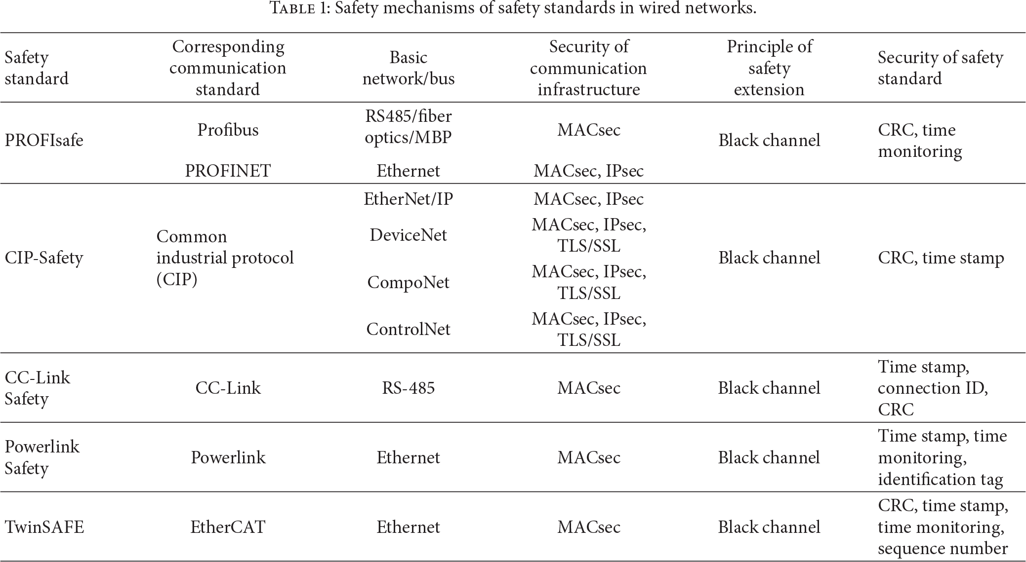
Safety mechanisms of safety standards in wired networks are shown in Table 1. In this paper, in order to explain the implementation principle of related security standards, we take PROFIsafe and CIP-Safety as typical examples for analysis in detail. Also, we analyze the basic principles of CC-Link Safety, Powerlink Safety, and TwinSAFE.
Safety mechanisms of safety standards in wired networks.
3.2. Principle of Safety Extensions for Wired Control Networks
Most of the safety standards can be regarded as the safety extensions of related communication standards in smart grid. The safety concepts of safety standards and the data security concepts of corresponding communication standards complement each other [22]. In other words, the security infrastructure of control buses/networks is based on data security foundation, which can provide the basic security for high level safety of safety standards.
Most safety standards of wired smart grid use the black channel principle for the transmission of safe data via a standardized network. The safe transmission function comprises all measures to discover faults and hazards that could be infiltrated by the black channel or to keep the residual error probability under a certain limit. Based on the black channel, safety-related schemes perform safe communication by using (1) a standard transmission system and (2) an additional safety transmission protocol on top of the standard transmission system. The black channel principle is shown in Figure 2.

Black channel principle.
3.3. Safety Extension Mechanisms in Wired Control Networks
This section analyzes the principle of encapsulated safety data at safety layer in wired control networks. Here we take the typical safety mechanisms as the examples for the analysis in detail.
3.3.1. Message Structure including Container
The safe data, consisting of the purely safety-related user data and the protocol overhead, are transmitted via standard control networks together with data that is not safety related. Here, we take CIP-Safety, for example, to do explanations. Figure 3 shows the telegram setup of a “Master Data Telegram (MDT) data field” within the scope of an Ethernet frame, which contains a configurable data container for real-time data of each device. The real-time data of a device are again divided into standard and safety data. The safety data are CIP-Safety telegrams either in the short format (2 bytes) or in the long format (up to 250 bytes).

Message structure of encapsulated safety data in CIP-Safety.
Note that not all the devices in the smart grid include the safety data container. In other words, just some devices perform CIP-Safety communications, which depend on their security requirements. The devices without CIP-Safety capability only send/receive data based on standardized CIP connections.
3.3.2. Cyclic Redundancy Codes Checksum for Integrity Check
Cyclic redundancy codes (CRCs) are used in most safety standards for integrity check. For example, PROFIsafe uses several different CRCs to protect the integrity of safety-related messages. The safety-related IO data of a safe node are collected in the safety payload data unit (PDU), and the data type coding corresponds to PROFINET IO. One safety container corresponds to one subslot in PROFINET IO. When the safety parameters have been transferred to the safe device, the safe host and safe device/module produce a 2-byte CRC1 signature [23] over the safety parameters. The CRC1 signature, safe IO data, status or control byte, and the corresponding consecutive number are used to produce the CRC2 signature as illustrated in Figure 4. The CRC1 signature provides the initial value for CRC2 calculation that is transferred cyclically, thus limiting the CRC calculation for each cyclic PROFIsafe container to CRC2. In Figure 4, the symbol “F” is used throughout the PROFIsafe to identify the “fail-safe” function component introduced. The F-Parameters are containing information for the PROFIsafe layer to adjust its behavior to particular customer needs and to double-check the correctness of assignments. F-Input and F-Output denote the input and output data of a PROFIsafe device, respectively.

CRC2 generation in PROFIsafe.
3.3.3. Consecutive Number for Delay Control
The consecutive number is used as a measure to deal with some of the possible communication errors. It is also used to monitor the propagation delay between transmission and reception. Each message is equipped with a consecutive number, which is used by the recipient for monitoring the life of the sender and the communication link. Both communication partners continuously check whether the other partner manages to update the consecutive number before a defined watchdog time has elapsed.
The consecutive number check was carried out on different versions of the PROFIsafe model, considering input and output slave configurations with different ranges of consecutive numbers. For example, a 24-bit counter is used in PROFIsafe for consecutive numbering; thus the consecutive number counts in a cyclic mode from 1⋯FF FF FF wrapping over to 1 at the end [23]. The consecutive number 0 is reserved for error conditions and synchronization. Here the consecutive number is called virtual consecutive number (VCN), because it is not visible in the safety PDU. The mechanism uses counters located in the safety host and safety device and the Toggle Bit within the status byte and the control byte increments the counters synchronously. The transmitted part of VCN is reduced to a Toggle Bit which indicates an increment of the local counter. The counter within the safe host and safe device is incremented at each edge of the Toggle Bits. Figure 5 illustrates the VCN mechanism. To verify the correctness and to synchronize the two independent counters, the consecutive number is included in the CRC2 calculation that is transmitted with each safety PDU.
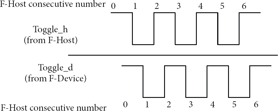
Virtual consecutive number.
4. Proposed Safety Extension of Wireless Control Networks
Based on aforementioned analysis, safety extensions are very necessary for industrial control networks with strong noise and interferences. For example, additive white Gaussian noise (AWGN) usually causes the error into WirelessHART and ISA100.11a [24]. However, to our best knowledge, most of the current standards of wireless industrial networks lace the consideration of safety. To address this, we propose in this section a safety extension scheme for the wireless control networks in smart grid. Here we modify and optimize the typical CRC to perform the safety extension of wireless industrial control networks.
A lot of error correcting schemes have been proposed. In particular, to realize message authentication, some error correcting methods are proposed especially for [25, 26]. AWGN is considered as the noisy channel model in the error correcting codes in [25, 26], which is a kind of usual noise in smart grid. In the proposed safety extension scheme, CRC, interweave technology, and the noise-tolerance message authentication method in [25, 26] are integrated seamlessly to realize the safety extension for wireless control networks.
4.1. CRC Combination Based Message Portion
Figure 6 shows the principle of message portion of the proposed scheme. At first, the scheme shuffles the message w times, so w submessages are generated. Then each submessage is divided into q blocks, each of which is input conventional CRC computation. Meanwhile a submessage of the original CRC of each block remains, which is called sub-CRC. Moreover, the original message is shuffled this step repeating m times with different “partition” into blocks. Note that a keyed pseudorandom number generator is used to perform the shuffle operation. Finally, the proposed scheme performs interweave operation for the sub-CRC for each partition and the outputs of interweave operation are then integrated together to produce a combined CRC, which is denoted as C-CRC.

Combined CRC based error correcting.
4.2. Error Detection and Correcting Algorithm
Procedure 1 presents the error detection and correcting algorithm. Here we use bit flipping of the bits with the lowest absolute reliability values (also called the log likelihood ratios (LLRs)) to realize the error correcting. As a matter of fact, the LLRs are the reliability values of the bits in messages received over a noisy channel. An LLR is assigned by the demodulator to each outputted bit using the magnitude of the signal 
Received message blocks: The partitioning routine and w The received C-CRC; C-CRC = LLRs of The maximum number of iterations:
Corrected/Authentic blocks and irrecoverable blocks
(1) For (2) For (3) If C-CRC verification succeeds, then go to (10). (4) Let (5) For (6) (7) End (8) Arrange the bits of (9) Flip the next combination of least reliable bits of (10) Success, mark (11) End. (12) Mark (13) End.
4.3. Evaluation of the Error Control
To evaluate the error correcting capabilities of access request/response, we do a simulation for the message based on Matlab. The message is assumed to be shuffled two times. A keyed pseudorandom number generator is used to select the blocks which form the partition, and each portion is divided into four blocks. The message length used in this simulation is 2048 bits. AWGN channel is considered as the noisy channel, which is a typical noisy channel in smart grid. We set the lower limit of SNR in our evaluation to be 6 dB according to the SNR range in [26]. Figure 7 shows the bit error rate (BER) against each value of the SNR. Based on the simulation results, it can be seen that BER as low as
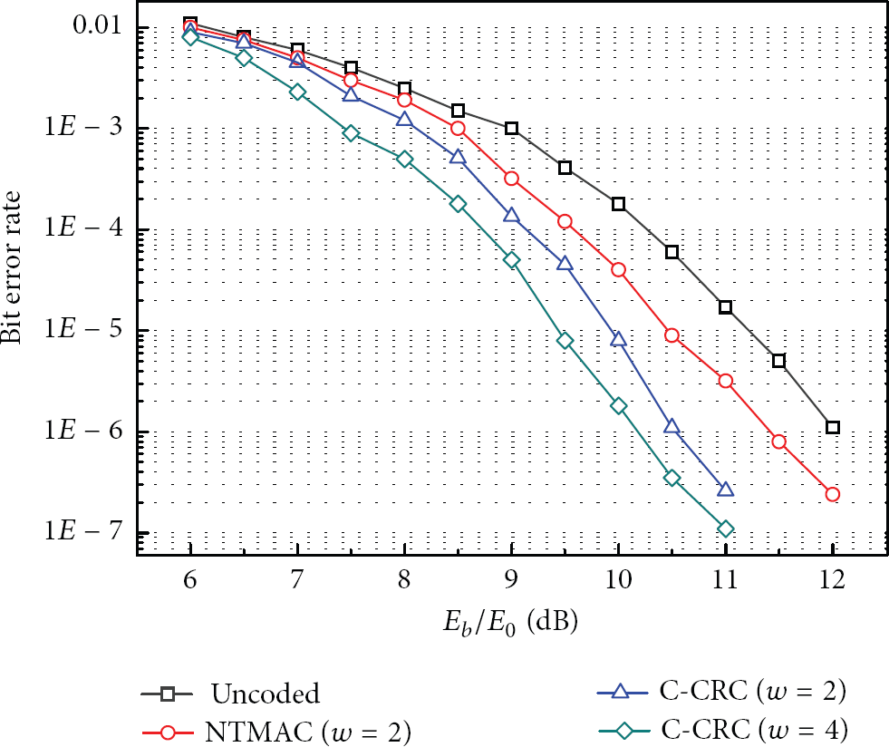
Safety capability under AWGN channel in smart grid.
Because the proposed scheme aims to provide safety in smart grid environments, we next evaluate the performances of the safety capabilities of the proposed scheme considering the power-line background noise and appliance impulsive noise, respectively. We use Nakagami probability density function (PDF) to model the power-line background noise based on the method in [27]. In addition, we use the parameters of best-fit distribution in [28] to model the appliance impulsive noise from various electric device noises. We perform the evaluation for the three cases: (1) only AWGN noise channel, (2) PLC channel with AWGN noise, and (3) PLC channel with both AWGN and impulsive noises. For the three cases, the bit error rates (BER) of the simulation results against each value of the SNRs are shown in Figure 8. As shown in Figure 8, additive BER can be caused by both PLC background noise and impulsive noise.

Safety capabilities under different noise models in smart grid.
5. Discussion
5.1. Safety versus Security
Safety is protection against random incidents which are unwanted. Security is protection against intended incidents which happen due to a result of deliberate and planned act.
Based on aforementioned analysis, both wired and wireless communication standards can provide the basic security for smart grid, including authentication, secrecy, and integrity check. These measures can deal with the network attacks.
In order to provide a set of safety services in smart grid, safety-related standards for wired smart grid have been proposed. The safety devices usually must realize more secure and reliable services than normal devices. Thus, more and more security measures are added into the safety standards for reliable communications. These safety standards can be regarded as the safety extensions of the communication standards. And the safety data can be transmitted based on these safety standards.
Note that there are only safety extension standards for wired communication standards but no safety extensions for wireless communication standards.
5.2. Safety Level
In IEC 61508, SIL means safety integrity level and constitutes a rating of the failure probability of a system based on IEC/EN 61508. The categories run from SIL level 1 to 4, with the probability of failure decreasing as the level rating increases. SIL 3 corresponds to a probability of failure of
All the wired communication standards can meet the requirements of IEC 61508 [2] safety integrity level 3 (SIL3). Some safety standards not only fulfill the SIL3, but also satisfy other requirements. The CIP-Safety concept has been approved by TÜV Rheinland for adoption in IEC61508 SIL3 and EN954-1 Category 4 applications. CC-Link Safety is a network with high reliability in data transmission suitable for safety applications that require compliance with IEC61508 SIL3 and EN954-1/ISO13849-1 Category 4. For Powerlink, the quality of these measures will fulfill the requirements of SIL 3 (and within specific architectures also SIL 4). Also, for Powerlink Safety, there is even the potential in this system to satisfy reliability and availability demands of Category SIL 4 according to IEC 61508. In practice, Powerlink Safety may cause no more than
5.3. Open Issues
This section discusses the open issues of the safety for control networks in smart grid.
5.3.1. Implementation Efficiency
Firstly, how to enhance the software and hardware implementation is very important. For example, experiences from a practical effort to build a WirelessHART protocol stack have shown that performing AES calculations in software on embedded platforms is too time consuming to meet the 10 ms time-slot requirements of WirelessHART. To fulfill the requirements, it is suggested to use an AES hardware accelerator. Many variants of the CBC-MAC can also be used to enhance the performance efficiency [26, 29, 30].
5.3.2. Safety Breach
There are many safety breaches in wireless and wired smart grid. The attacks can occur to the safety data in the safety extension standards. The analysis in [31] shows that it is possible to attack PROFIsafe and change the safety-related process data bypassing any of the safety measures in the protocol. By getting one safety container and using brute force to compute all valid combinations of CRC1 and VCN that generates the same CRC2 as in the received message, a set of possible CRC1 can be obtained. With the knowledge that the CRC1 is static over the session lifetime, the remaining combinations can be reduced down to the CRC1 that is in use. An iterative process will be done till the correct CRC1 has been found. After that, the remaining challenge is to look for the actual VCN soon for all received safety containers. The VCN will increase depending on the period time of bus, host, and device executing the safety layer. If the attack is performed very fast and can receive all safety containers, the VCN would not be updated for each frame received, thus relaxing the computational efforts to derive the VCN in “real time.”
6. Conclusion
The analysis and extension of safety mechanisms of standardized control networks in smart grid are given in this paper. Firstly, safety threats and requirements are analyzed. After that, the safety mechanisms of wired control network standards including Profibus, PROFINET, CIP, CC-Link, Powerlink, and EtherCAT are analyzed and studied deeply. More importantly, we proposed a combined CRC safety mechanism to perform the safety enhancement for existing wireless control networks, and its effectiveness is validated by simulation results. Finally, key points and open issues of safety-related mechanisms are discussed. The main contributions of this paper are the analysis for the safety of the wired standardized control network and the proposed safety extension mechanism for wireless control networks, which are meaningful to improve the safety for smart grid.
Footnotes
Conflict of Interests
The authors declare that there is no conflict of interests regarding the publication of this paper.
Acknowledgments
This work is supported by National Natural Science Foundation of China (Grant nos. 61171173 and 61372049). This work is also supported by Key Lab of Information Network Security, Ministry of Public Security and Key Laboratory of Infrared System Detection and Imaging Technology, Shanghai Institute of Technical Physics, Chinese Academy of Sciences. Particularly, the authors would like to thank the anonymous reviewers for their valuable comments to improve the presentation of this paper.