
Abstract
Compared with traditional charging method, CPT (contactless power transfer) is more convenient and safe while having higher power lose. Therefore, the efficiency of CPT needs to be optimized. In this paper, PSSS (primary side series compensation and secondary side series compensation) model is used to study the efficiency optimization of a high-power CPT. The factors such as coil structure, resonant frequency, and load matching on high-power CPT charging equipment are studied by simulation and experiment. The results show that system efficiency is proportional to mutual inductance values; coil structure mainly affects the mutual inductance values; the mutual inductance of the coils is mainly affected by the diameter of the coils, the distance between the coils, the shape of coil, the number of turns, and so forth. As for the CPT charging system based on full-bridge inverter circuit, the efficiency of the system increases as the frequency increases in the range of 0–50 kHz, while decreases as the frequency is higher than 50 kHz. Load matching also affects the efficiency of high-power CPT charging equipment, and the load matching formula based on an equivalent circuit model is given.
1. Introduction
Using the traditional mode to charge electric vehicles, the exposed energized conductors easily produce sparks and may cause poor contact, electric shock and other accidents, which brings potential safety hazard to the user. It is not suitable to utilize wire-contact charging when it comes to bad weather such as rain, snow and so forth, those phenomena affect the normal outdoor charging and running of electric buses, sanitation vehicles and other public vehicles. Furthermore, electric vehicles used in exceptional circumstances, such as airport shuttle bus, are also facing charging challenges [1]. Recently, CPT charging draws more and more attention. Compared with the traditional charging method, CPT charging has several advantages, such as no manual plugs, saving wiring materials, no electrical hazards and strong adaptability under adverse weather conditions; it is convenient to popularize in the parking lots and garages. With the further development of new energy vehicles and the gradual expanding of the market for electric cars, CPT charging with broad prospects will get a rapid development.
Since the 1990s, people began to do further research on inductive power transfer to meet the needs of the various walks of life for CPT. Foreign universities, such as University of Auckland, Sojo University, Northeastern University, and Stanford University, and enterprises, such as Germany's Siemens, the US General Motors Corporation, and Qualcomm, have carried out some researches and developments on electric vehicle CPT charging system of medium and high power. The power of the CPT charging system developed is mostly in the range of 2 kW~20 kW, and the efficiency can reach 90% [2].
The most influential of whom is the physicist Marin Soljacic who come from Massachusetts Institute of Technology (MIT) verified the magnetic resonance energy transfer method in 2007, since then wireless power charging received much more attention. The wireless charging system WiT-3300 which they developed has an efficiency of more than 90%, under the parameter that the distance is 18 cm and the power is 3.3 kW.
In this paper, the influence of various parts of the circuit on the efficiency of the system is studied by analyzing the equivalent circuit of electric vehicle CPT charging circuit, studying the influence of coil shape, size, and other factors on the efficiency through magnetic simulation of different coil structures using Maxwell software; use Simulink software to simulate the whole system, study the relationship between several parameters, and obtain preliminary conclusions; finally, verify the calculations and the preliminary findings of the simulation above and summarize efficiency optimization method of electric vehicles high power CPT.
2. Analysis of Principle of Electric Vehicle CPT Charging System Efficiency
Energy loss is mainly caused by two factors during the process of CPT charging: heat loss [3] (or copper loss) generated by charging coils when current passes through and part of the energy loss caused by radiation. The key of improving efficiency is how to reduce the loss of the two parts.
2.1. Analysis of Circuit Loss
Without considering the energy loss caused by radiation of the charging coils, use an equivalent circuit that represents the CPT charging circuit of electric vehicle, as shown in Figure 1. The power supply part is a high-frequency AC power in the equivalent circuit, and two charging coils are equivalent to two mutual inductance coils, L1 and L2. Their mutual inductance value is M. The resistance of the coils is equivalent to two resistors R1 and R2. In this paper, the compensation type is PSSS [4]. Make bilateral series compensation with capacitors C1 and C2 to further improve the efficiency. Use resistance R L that represents the batteries of electric vehicles.
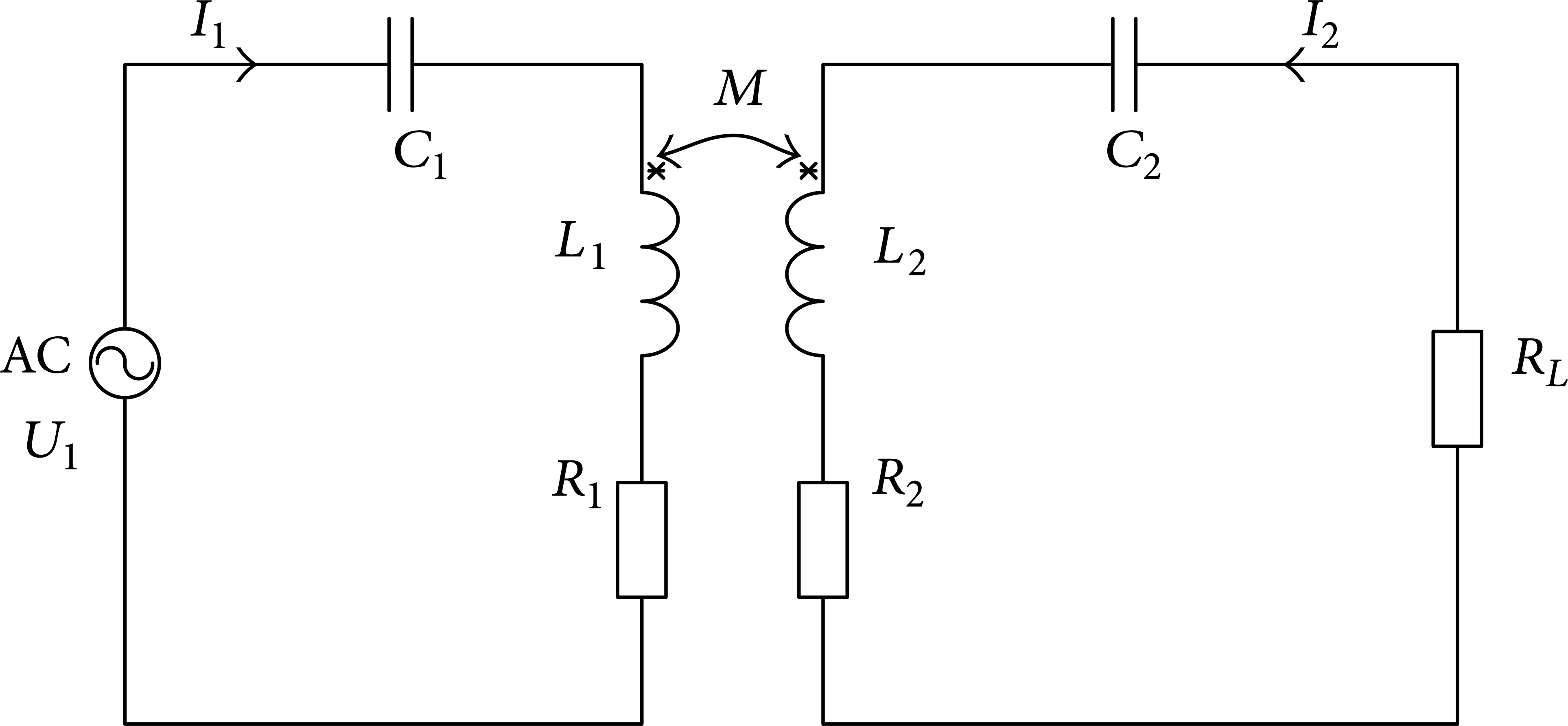
An equivalent model of a CPT charging circuit.
Do mathematical analysis on equivalent circuit; list the following equations and solve them:
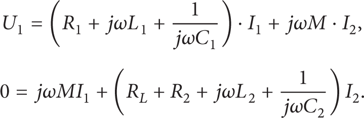
When resonating

Solve the matrix equations and the current of both sides of the coil when resonating can be obtained:
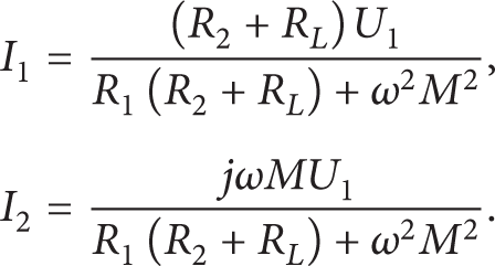
Transmission efficiency of the system:

From formula (4), CPT charging system efficiency is positively correlated with the frequency f of the AC power and the mutual inductance M.
The efficiency also has a relationship with the load resistance. Take the partial derivative of formula (4) of the load resistance R L ; when
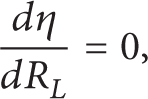
the optimum matching between loads and efficiency can be obtained:

What can be obtained from the above formula is that the optimum efficiency of the system has a direct relationship with the working frequency, the mutual inductance value of the coils, and the load resistance. How to match a good relationship between the three is the key issue of efficiency optimization.
2.2. Analysis of Radiation Energy
As for systems at a larger distance, magnetic induction line generated by the coil has no specific routes, which increase the difficulty of magnetic circuit computation. Thus, the energy wasted through radiation cannot be analyzed quantitatively.
In this paper, Ansoft/Maxwell software is used to analyze the magnetic field between the two coils. The optimal coil design approach is obtained by creating different models of the primary coil and the secondary coil. Namely, compare the number of turns, size, and shape of different models, and whether those models have a magnetic core. Thereby radiation energy loss reduces and the efficiency of the system improves.
As shown in Figure 2, the first is a disc coil model, while the second is a solenoid model. Set the coil turns N = 5, OD = 20 mm, the gap between the coils is 10 mm, and the current value of the primary coil is 10 A. The results are shown in Figure 3.
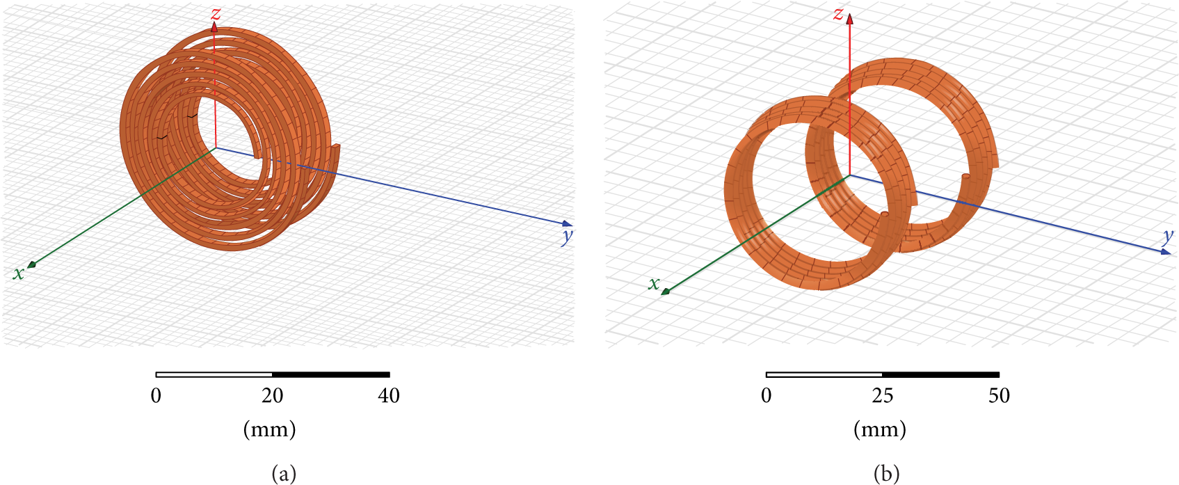
Disc coil model and solenoid model.

Magnetic flux density of disc coil and solenoid at the secondary side.
Do the comparative experiments of area and turns. In the comparative experiments of turns, the first group of coil is 4 laps while the second is 8 laps; two groups have the same area and gap. In the comparative experiments of area, select a single coil with the same gap; the radius of the first is 20 mm while the second is 40 mm. The results are shown in Table 1.
Results of magnetic circuit analysis.

The conclusions of the magnetic circuit simulation are as follows.
When the excitation current of primary coils is the same, but the number of turns are different, the magnetic flux density received by the secondary coils is significantly different. Because the receiving areas are the same, the greater the magnetic flux density, the greater the magnetic flux received, so the mutual inductance values are different. The more the turns, the greater the mutual flux, the greater the mutual inductance value M.
Coil area has an impact on the magnetic flux. When excitation currents are the same, the magnetic flux densities are almost the same. However, because of the different areas of the coil, from the formula Φ = BA, the larger the area, the greater the flux. In the experiments, when r = 40 mm, the secondary receives greater magnetic flux. So the larger the area, the greater the mutual inductance value M.
When the number of turns and the area are both the same, the mutual inductance value M generated by the disc coil is larger than that of the solenoid coil.
Conclusion. Choosing a disc coil with more number of turns and larger area can increase the degree of coupling between the coils and reduce the proportion of energy radiation loss. Thus, the efficiency is improved.
3. System Simulation and Efficiency Analysis
As shown in Figure 4, the mutual inductance coil model used in the simulation system simulates the primary and secondary sides. Build an inverter circuit in the primary side and a rectified circuit in the secondary side. Simulate the working frequency, the coil position, and the load changes in actual work by adjusting the frequency of the PWM generator, the mutual inductance value of the mutual inductance coil, and the load resistance R L .
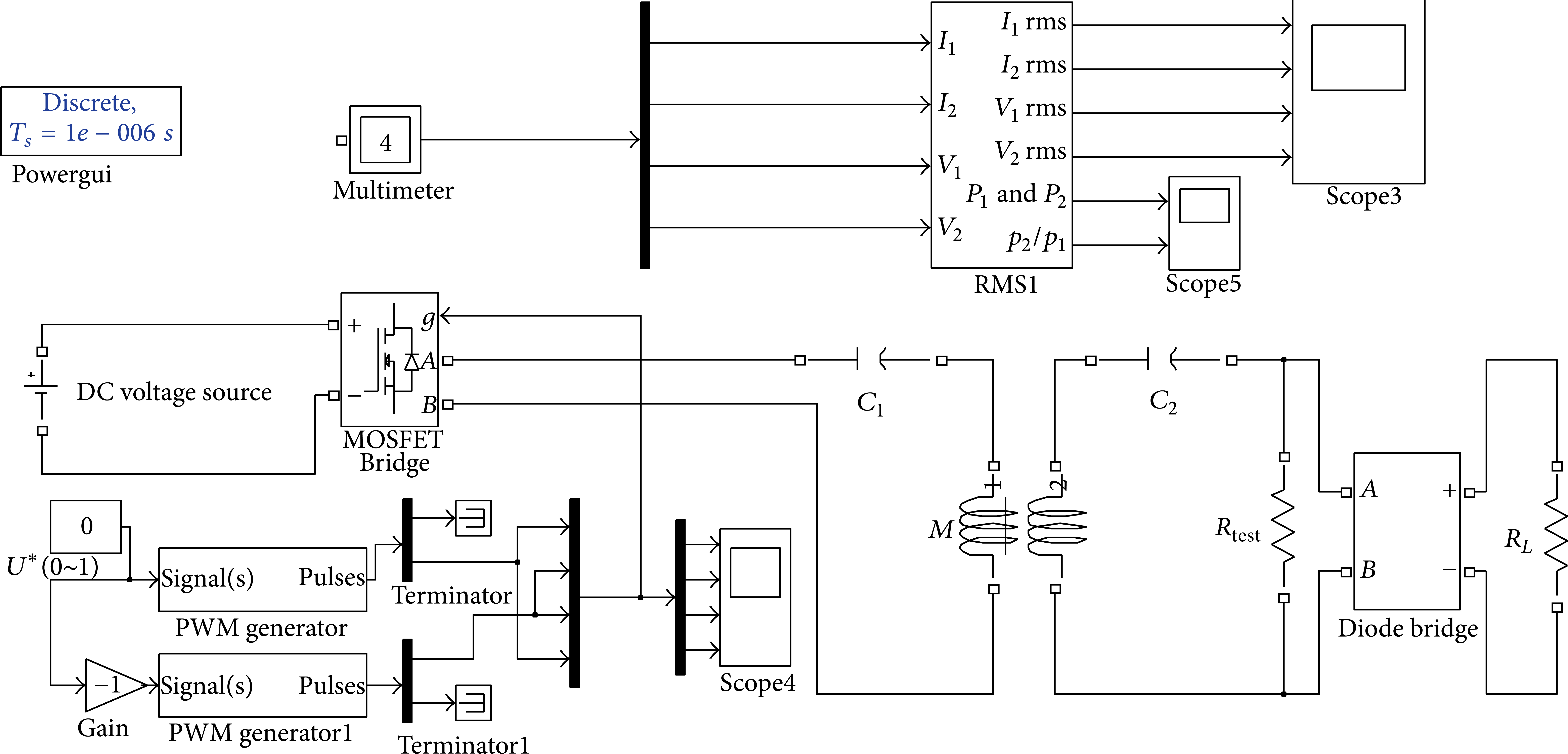
Simulation model of CPT charging system.
Set the DC source value 700 V, the mutual inductance value M = 150 μH, the coil inductance L1 = L2 = 700 μH, and the resonant capacitor value 20 nF. The resonant frequency calculated is f = 42535 Hz; the optimum matching load resistance is R L = 40.09 Ω.
3.1. Influence of Frequency on Efficiency
In the simulation experiment, set the resonant capacitor capacitance of 30 nF, 20 nF, and 10 nF, keep the coil inductance value unchanged, and get three different resonant frequencies which are 60 kHz, 42.5 kHz, and 34.7 kHz.
When the working frequency of the system is close to the resonant frequency, the efficiency of charging system is the highest. In the simulation experiments, set different capacity values of the resonant capacitor and keep coil self-inductance value unchanged; three different resonant frequencies are obtained. Three groups of efficiency curve under different frequencies are shown in Figure 5.
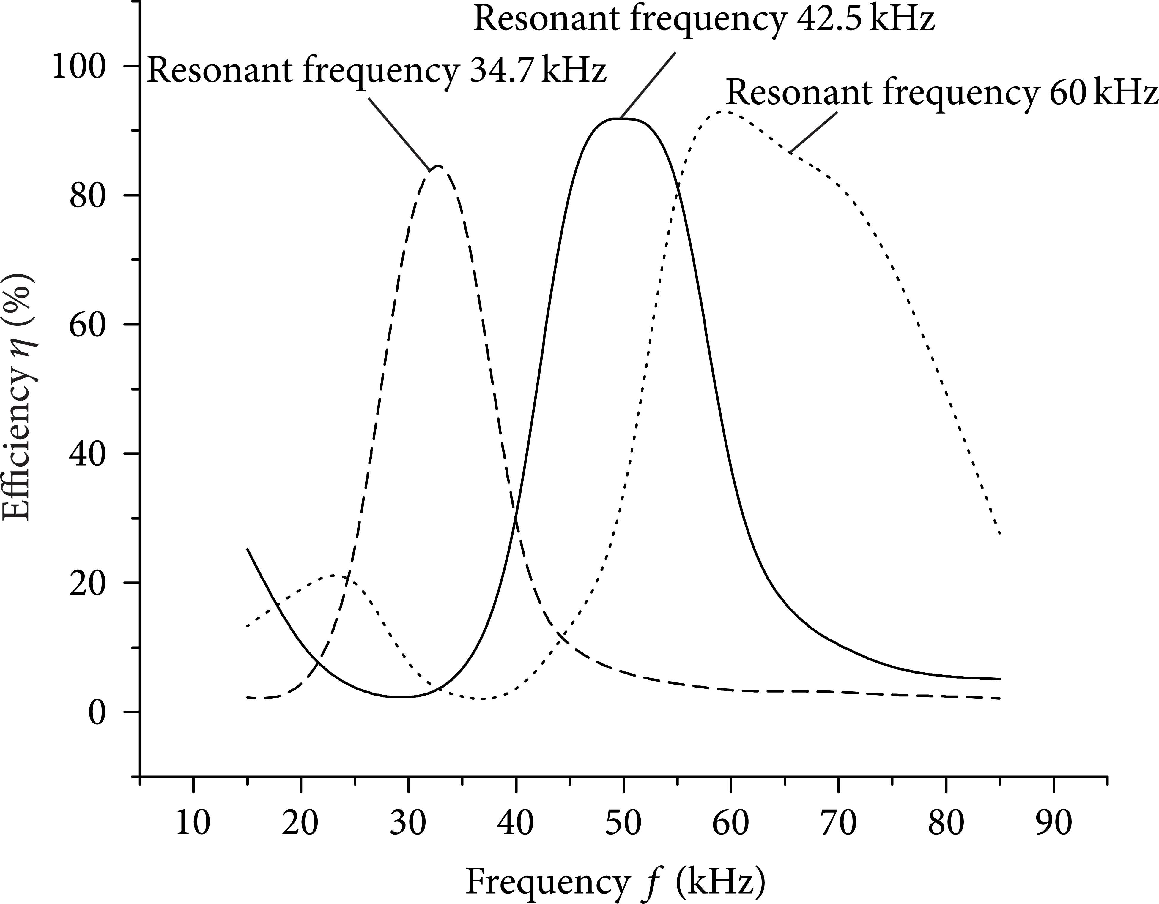
Influence of frequency change on efficiency.
From Figure 5, resonant frequencies are different under different capacitor values, and when the frequency is close to the resonance frequency, the maximum efficiency is achieved in each group. According to the comparison between different groups, the higher the resonant frequency is, the higher the efficiency is. In Figure 5, two curves whose resonant frequency is 42.5 kHz/60 kHz have a slight increase at low frequencies, which is caused by the higher harmonic of the AC voltage signal. Figure 6 shows the efficiency trends under different matching resonance frequencies. The higher the resonant frequency is, the higher the efficiency is.

Influence of resonant frequency on efficiency.
3.2. Influence of Load on Efficiency
Changing load also has a great influence on efficiency. Set different values of the load R L range in 10 Ω~500 Ω and do simulation experiment in three groups of matching resonant frequency. Figure 7 shows the efficiency trends under different loads. When the load resistance is close to the optimum matching, the optimum efficiency is achieved. However, the efficiency can only reach about 30% if the load is too small or too large. It can be inferred that the efficiency will drop to 0 in some extreme cases such as when the load of secondary side is short-circuit or open-circuit. The same results can be seen in Figure 7; the higher the frequency is, the greater the efficiency is.

Influence of load changes on efficiency.
3.3. The Influence of Mutual Inductance Value on Efficiency
In the actual application of CPT charging system, a variety of conditions can cause the mutual inductance between the two coils change which will affect the efficiency of the system, such as coil position changes or the gap between the coils changes. Set mutual inductance value M range from 50 μH to 500 μH. Conduct two simulations to simulate the influence of different gap between the coils and coil position changes on efficiency. The first does not match the load resistance while the second matches. The results are shown in Figure 8.

Influence of gap variation on efficiency.
From Figure 8, there is a positive correlation between mutual and efficiency. In addition, in the group whose load resistor has been matched, the efficiency increases more significant with the increase of mutual inductance.
4. Experiment of CPT Charging System
In order to conduct the transmission capacity of CPT charging, related experiment needs to be done. In the experiment, primary and secondary coils diameter is 80 cm and the shape is double-disc. The gap between the two coils is adjustable to get different mutual inductance values. The coil resistance is 0.1 Ω; resonant capacitor chooses polypropylene film capacitor whose capacitance value is 20 nF; power supply is a DC source whose output value is 700 V; choose a load box whose power is 20 kW and whose resistance can be adjusted; inverter circuit adopts full-bridge inverter topology, the output voltage frequency of the circuit ranges from 20 kHz to 150 kHz, and its maximum output power is 15 kW. Figure 9 shows the experimental setup of CPT charging.

Experimental setup of CPT charging.
4.1. Frequency Variation Experiments
In order to compare the efficiency of different resonant frequencies, research on impact of frequency on the system is divided into three groups. The polypropylene film capacitors of 10 nF, 20 nF, and 30 nF and the primary and secondary sides of the coils are in series, respectively. The resonant frequencies are 34.7 kHz, 42.5 kHz, and 60 kHz. Figure 10 shows three groups of curves of efficiency changes with frequency. Come to a conclusion as simulation experiment. It should be noted that the efficiency of the group which has a resonant frequency of 42.5 kHz is higher than that of the group which has a resonant frequency of 60 kHz. This is because the increase in the frequency led to an increase of loss of the inverter circuit.

Influence of frequency variation on efficiency.
To further verify the impact of the inverter circuit loss on the efficiency of the system, conduct several experiments through changing the resonant frequency of the system and match different resistance values at the same time. Figure 11 shows the curve of working efficiency under different resonance frequencies. The efficiency of high power CPT charging system based on full-bridge inverter circuit increases as the resonance frequency increases in the range of 0~50 kHz; however, the efficiency of the system decreases as the resonance frequency increases when the resonance frequency is higher than 50 kHz. Therefore, in this experiment which uses full-bridge inverter circuit as the input power, the optimal efficiency is achieved when the frequency is close to 50 kHz.

Efficiency of the system under different resonant frequency.
4.2. Load Variation Experiments
In the experiment of load variation, choose a load box whose power is 20 kW and whose resistance can be adjusted; load resistance varies in the range of 10 Ω~500 Ω. As shown in Figure 12, the optimal efficiency is obtained when the load is close to the optimum matching load.

Influence of load variation on efficiency.
4.3. Mutual Inductance Variation Experiments
Distance changes between the primary and secondary coils will significantly affect the mutual inductance value. Mutual inductance value of different distances between the coils used in the experiments is obtained after measurement and calculation. Set the working frequency of the system at 42.5 kHz, and calculate the matching load resistance. The mutual inductance values of the coils and the matching resistance values are shown in Table 2.
Mutual inductance of different spacing.
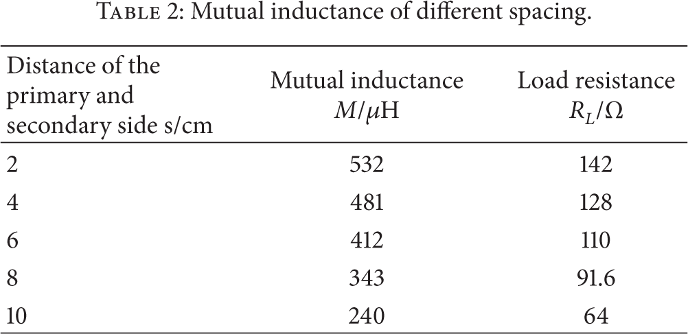
Mutual inductance variation experiments are divided into two groups. In the he first group, the load resistance is not matched; keep the resistance unchanged at 64 Ω, while the load resistance is matched in the second group. In this way, impact of distance as well as matching resistance on efficiency can be observed. As shown in Figure 13, the efficiency increases as the mutual inductance value becomes larger. In the he first group, when the distance of the coil is 2 cm, efficiency of the system is lower than when the distance of the coil is 4 cm because of absence of matched resistor, which further validate the importance of matching resistor on system optimization.

Influence of distance variation on efficiency.
4.4. Different Coil Structures Experiments
The inductance and mutual inductance of different coil structures under the same area are different. In order to obtain a higher transmission efficiency, the impact of coil structure on efficiency should be considered when designing the coil. Equation (4) shows that the transmission efficiency is positively correlated with the mutual inductance values.
In the coil structures experiments, a comparison of two kinds of winding ways (disc coil and solenoid coil) has been made. In addition, a comparative experiment about coils with an iron core is also conducted to study the impact of magnetic materials on mutual inductance value. In the experiments, both of the coils are a disc with a diameter of 25 cm and their wire turns are both 10 turns. The results of the comparison are shown in Table 3.
Comparison of mutual inductance values of different coil structures.

As we can see from the results, mutual inductance value between disc coils is higher and mutual inductance value of coils with an iron core is slightly higher than that of coils without iron core. When closer, the degree of coupling between the coils improves a lot due to the iron core. It can be inferred that the iron core has little influence on the degree of coupling when the distance is large enough. In summary, disc coils are a better choice to improve efficiency. To further improve the efficiency, ferromagnetic material can be added to the coils when the distance is short relatively.
5. Conclusions
Through theoretical analysis, simulation, and experiments, methods of improving CPT charging system efficiency for electric vehicle can be drawn.
Simulation and experiment results show that system efficiency is positively correlated with mutual inductance values, coil structure mainly affects the mutual inductance values between the coils of transmitting terminal and receiving end, and the mutual inductance of the coils is mainly affected by the diameter of the coil, the distance between the coils, the shape of coil, the number of turns, and so forth. Choose disc coils with more turns and larger area when designing. To further improve the efficiency, we can add magnetic materials along the magnetic field lines around the coils.
During working, the higher the frequency, the higher the efficiency of the system. Match the corresponding capacitor based on the coils designed and obtain higher operating frequency by reducing the matching capacitor value. The efficiency of high power CPT charging system based on full-bridge inverter circuit increases as the resonance frequency increases in the range of 0~50 kHz; however, the efficiency of the system decreases as the resonance frequency increases when the resonance frequency is higher than 50 kHz. Too high frequency will result in decrease of the overall efficiency of the system. Therefore, the inverter circuit should be considered when choosing the operating frequency; thus, the system operates at the working frequency of the optimal efficiency.
Calculate the resistance value of the optimum matching load according to the coil designed and the frequency, and the equivalent load values of the secondary side circuit should match the resistance of the optimum matching load.
Conflict of Interests
The authors declare that there is no conflict of interests regarding the publication of this paper.