
Abstract
Current sensor networks have various types of sensor devices with different network protocols. Most users directly connect to the sensor devices with limited IT capabilities. This ad hoc method of using sensor networks has many limitations. First, multiple users cannot share a sensor device at the same time. Second, users cannot deploy applications for various sensor devices easily and quickly. To solve these problems, we propose the innovative IaaS management system for sensor devices in which the sensor devices are managed as one of the IT resources in the same way as CPUs, storage, and networks in the cloud computing. We call this cloud environment “Sensor Cloud (SC).” SC allows multiple users to share the sensor devices instead of the sensor data. SC adapts three cloud features for sensor devices, “virtualization,” “automation,” and “standardization.” We implemented SC and deployed it on actual server environments hosting the existing cloud software. The evaluation results of SC show that the transmission delay for sensor data between the sensor devices and the users in SC was decreased by up to 81% compared to a typical cloud computing implementation.
1. Introduction
Many objects are receiving embedded sensor devices with communications capabilities in the Internet of Things (IoT) [1] environments. Applications in the IoT sometimes need various specialized sensor devices to sense a specific environmental factor. In such an environment, where the IT resources of most sensor devices are limited, here are some typical problems. (1) Only one user can use a sensor device at one time because of the limited resources of the sensor device. (2) Users must configure the parameters of software to connect to the sensor devices. (3) It is difficult for users and developers to deploy sensor-based applications because each sensor device uses its own API and network protocols. We created “Sensor Cloud (SC)” to solve these problems with sensor devices. SC is a cloud computing environment in which the sensor devices are managed as one of the IT resources in the same way as CPUs, storage, and networks to provide Virtual Machine (VM) and sensor devices for multiple users [2, 3]. We have adapted three key features of cloud computing to sensor networks and devices: (1) virtualization, (2) automation, and (3) standardization. SC uses these features to provide a sensor device infrastructure in which users can easily access and share them. In our system, the required procedures for the users to acquire the sensor data are just selecting the sensor devices and provisioning an appropriate VM with a Web-based GUI. Users can also acquire the properties of the sensor devices, such as the battery status, network states, and transmission rates, because they can share a sensor device itself as a virtualized sensor device in the VM. The administrators of SC can monitor the sensor devices, as well as billing users for sensor data usage. SC can offer sensor devices to multiple users as one of the types of IT resources.
The remainder of this paper is organized as follows. Section 2 discusses some related works on shared sensor devices. In Sections 3 and 4, we describe the design of our SC that manages the sensor devices as shared IT resources. We implemented SC in actual cloud computing environments as described in Section 5 and evaluated it in Section 6. Section 7 describes some suitable applications for the SC. Finally, we conclude the paper in Section 8.
2. Related Work
SC provides a sensor device infrastructure in which user can use the shared sensor devices easily in a VM. We studied and categorized related work in which the users can share sensor devices or sensor networks.
Virtual Network. Here is the related work in which overlay networks are constructed from the sensor devices to utilize the existing network access methods and network protocols to the sensor networks. Users can seamlessly connect to the various sensor devices without any considerations of the differences among the sensor devices because the applications can use standard APIs and network protocols in the virtual overlay network [4, 5]. Both methods allow users to connect to the sensor devices seamlessly with the existing network application. However, it is impossible for multiple users to share a sensor device at the same time in the virtual networks because they must connect directly to the sensor device, which has limited IT resources such as CPU and the battery.
Sensor Data Sharing. We show some related works which have proposed the method of sharing sensor data. This method will allow many users access the DB which keeps the sensor data [6, 7]. The goal of these systems in which multiple users share only the sensor data is different from that of SC. In SC, users and developers can get the information about the sensor device's status such as the routing information, battery status, transmitting power, and signal to noise ratio as well as sensor data because SC virtualizes the sensor devices and manages them using a cloud computing architecture. For example, if the sudden interruption of sensor data in the multihop sensor networks occurs, the users need to know the status of the intermediate nodes to check the sensor networks. When the locations of the sensor devices are far from the users, it is difficult for them to check the sensor devices directly. If the shared sensor data does not have the real-time status of the sensor devices, users do not have any methods to examine the status of sensor networks to determine whether or not the network disconnection will recover soon. SC monitors and manages the status of the source, destination, and intermediate nodes to report on the real-time status of the sensor devices for the users and developers. Users can get the status of all the sensor devices remotely and realtimely in SC.
Testbed for Sensor Networks. There are some papers about testbeds for the sensor devices with various technologies [8, 9]. The goal of these projects is that multiple users can develop the embedded software for sensor devices by sharing the sensor devices. They can compile and reload their own software to the sensor devices because they can connect directly to the sensor devices. This method of sharing the sensor devices cannot share the sensor devices with many users at the time because of the resource limitations of the sensor devices. In SC, many users can easily get the various sensor's data and the status using the virtualized sensor devices, but they cannot develop the embedded software of the sensor device.
Cloud Computing. The related work in this area involves methods to share the sensor devices using a cloud computing architecture [10, 11]. These related projects provide methods to share not the sensor devices but only the sensor data in the applications or services in the clouds. Such a framework is called software as a service (SaaS). SC provides the virtualized sensor devices in the form of infrastructure as a service (IaaS). When the users need to develop applications or middleware for the sensor devices, the SC offers more benefits for such the users than an SaaS framework because users can use the sensor device itself in the VM. In addition, if the administrator creates a template with the middleware, sensor applications, and sensor devices, then SC can also provide the service in the same form as SaaS. Our system can flexibly provide the Virtual Sensor Devices in the forms of IaaS or SaaS to both these users who only use the sensor applications and the developers who create the middleware and applications. Other related works about the cloud computing are integrating the some peripherals with cloud computing [12, 13]. These related projects provide the frameworks by which all or a part of the function of the peripheral can be executed in the cloud environments. Our approach and goal are that the user can use the sensor devices themselves in the VM by the virtualization of the sensor devices.
3. Sensor Cloud
We integrated sensor devices for cloud computing to manage them as one of the IT resources in the same way as CPUs, storage, and memory. SC provides a system to share sensor device between multiple users and developers by supporting three-key functions, virtualization, automation, and standardization, for the sensor devices. We assume that target users of SC are both the developers who create the sensor applications and the end users who only use the sensor applications. Thus, SC must provide environments where users and developers use VMs with the required sensor devices and applications easily and without deep knowledge of the sensor devices. SC needs to provide benefits for owners who offer to share their own sensor devices in SC as one of the sensor devices. We offer two kinds of benefits for the owners: accounting and monitoring functions. The accounting system can calculate the usage fees for sensor devices. The cloud provider collects and transfers the usage fees to the owners. Moreover, owners can use the monitoring system to detect anomalies in the sensor devices and notify it to them.
SC provides three features to build the cloud environments for the sensor devices. (1) Virtualization: multiple users can connect to the various sensor devices without worrying about the differences among the sensor devices in the VMs. (2) Standardization: the sensor devices are divided into groups. SC registers VM template with the sensor applications and the sensor groups. When users want a sensor application and some sensor devices, they only have to select the VM templates and provision the VM from the catalog. Users need not have detailed knowledge about the required sensor devices. (3) Automation: SC automatically provisions and configures the VMs including the Virtual Sensor Devices, the sensor applications, and the libraries. Users can immediately develop or use the sensor applications in a VM. These three functions provide “Management of Sensor Devices.” Although the functions for Management of Sensor Devices are common functions for the cloud computing, we cannot directly adapt the existing virtualization systems, such as CPU, HDD, and memory virtualization, to the sensor devices. Common software for the virtualization does not include the function to support the virtualization of sensor devices (e.g., VMwawre, KVM). Moreover, the existing Cloud Manager software manages and configures only typical IT resources and does not support the virtualization software for the sensor devices. We must create a new system for the virtualization and management of the sensor devices in the cloud computing environment.
3.1. Management of Sensor Devices
The Management of Sensor Devices adapts the cloud computing features for the sensor devices as IT resources to share them with multiple users with a virtualization function. Figure 1 shows the user's view of the use of sensor devices in SC. (1) Information about the properties of the sensor devices (e.g., data formats, types of sensor devices, locations, and hardware specifications) is collected in the catalog of SC. Users select the VM template with the sensor devices from this catalog. (2) The users notify SC Manager of the VM templates with the sensor devices. (3) When SC Manager receives the requests from the users, this manager configures the IT resources to provision VM. (4) SC Manager virtualizes and installs the required sensor devices in the VM. Finally, the VM is provisioned in Sensor Cloud. The users can use the virtualized sensor devices within the VM in the same way as the actual sensor devices.
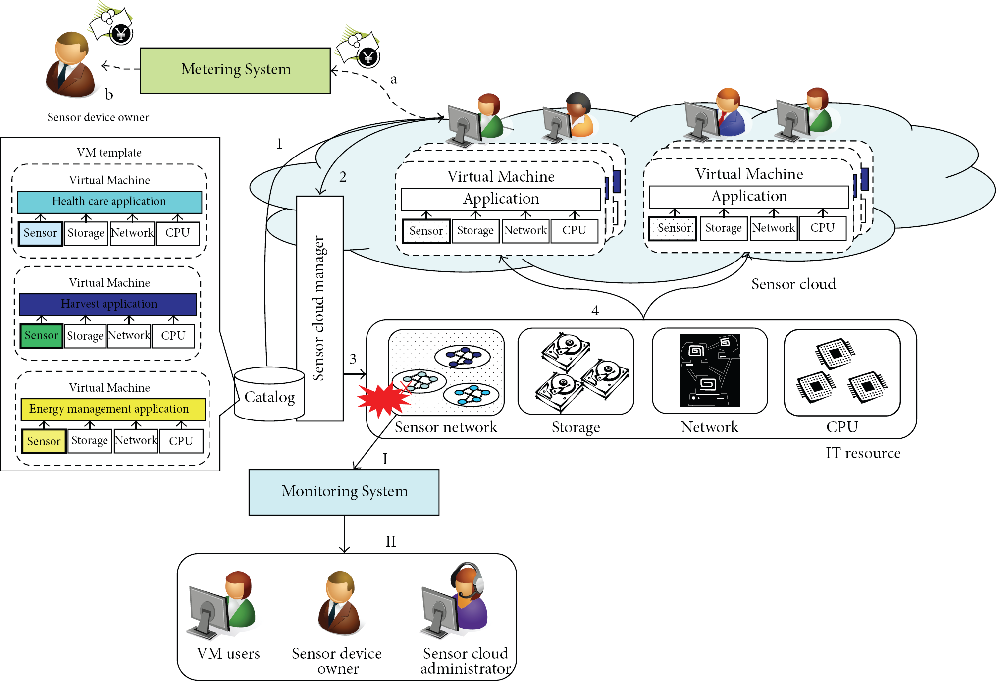
Sensor Cloud architecture: Management, Metering, and Monitoring System for sensor devices.
3.2. Metering of Sensor Devices Usage
We need to transfer the usage fees for sensor devices back to the owners for the business model of SC. SC Manager can collect information about the IT resource usage of the provisioned VMs. We can use this feature for a Metering System of the sensor devices based on an existing system which charges usage fees of typical IT resources such as CPUs and storage. This Metering System for SC collects the information about the usage fees for the sensor devices, such as the number of required sensor devices in the VM and the amount of sensor data, or the usage period of the sensor devices. Figure 1 shows overview of Metering System for the sensor devices. (a) The required sensor data is transmitted to the provisioned VM. SC Manager collects the information about the sensor data usage. Metering System calculates each user's fee for the sensor device usage from this information with the defined fee policies. Users pay the usage fee calculated by Metering System. (b) The usage fees are transferred to the owners who offer own sensor devices to SC.
3.3. Monitoring of Sensor Devices
We provide a Monitoring System to the owners to support the business model of SC. SC Manager can also collect the states of all IT resources in SC. We use this function for a Monitoring System to detect unusual states of the sensor devices based on the existing system that monitors the typical IT resources such as CPUs, storage, and networks. When this monitoring system detects any unusual state of the sensor devices in SC, it reports these anomalies to the administrators of SC and the VM users. Figure 1 is an overview of the Monitoring System. (I) When SC transmits the sensor data to the VM, it simultaneously reports to SC Manager about these transmission events. If the sensor device generates the sensor data only when it receives a request of the sensor data, then SC Manager sends periodic keep alive messages to the sensor device. These events involving the data transmissions are forwarded to the Monitoring System by SC Manager. Monitoring System periodically verifies whether the sensor devices are sending sensor data and replying to keep alive messages or not. (II) When the Monitoring System detects that sensor devices are not responding, it reports this abnormal status to the VM users and the administrators.
4. Design for Management of Sensor Devices
SC uses the same architecture as a typical cloud computing to manage their typical IT resources and the sensor devices. First, we need a new “hypervisor” to virtualize the sensor devices. This hypervisor for the sensor devices creates the virtualized sensor devices which users and developers use in their VMs in the same way as the normal sensor device. Users can obtain the sensor data and properties through these virtualized devices. Second, we need a new Cloud Manager that automatically configures the new hypervisor for the sensor devices to allocate the virtualized sensor devices that users request as IT resources in the VM. Finally, we need a function that obtains the properties of the sensor devices and adds a template with the grouped sensor devices and software to the catalog. Figure 2 illustrates the architecture of SC. SC has three modules to realize the requirements: (1) a hypervisor module to virtualize the sensor devices when SC Manager provisions the VM. Users can acquire the sensor data as well as the properties of the actual sensor devices by this virtualized sensor device in the VM; (2) autoconfiguration for SC Manager to allocate the virtualized sensor devices dynamically to the VM; (3) a catalog to hold the template of the sensor devices, the normal IT resources, software, and these pieces of information. In addition, the hypervisor must easily support various sensor devices and many users must be able to share each sensor device without large delay. We also have to consider for the hypervisor that the resources of the sensor devices are much limited.
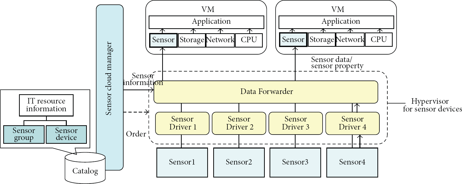
System architecture of SC: Virtual Sensor Devices, Data Forwarder, and Sensor Driver Module.
The provisioning process for SC is as follows. The users select the sensor devices and IT resources as the template with Web based GUI in SC Manager. SC Manager sends requests to a generic hypervisor to allocate the normal IT resources to the appropriate VM. After provisioning the VM, SC Manager sends the request to the hypervisor to create the virtualized sensor devices within the VM. SC can support both types of sensor networks, singlehop and multihop networks, as long as the SC can get the properties and data of the sensor data through the gateway or bridge node with TCP/IP protocols. Next, we explain the detailed design of the Management of Sensor Device.
4.1. Virtualization
Our hypervisor for the sensor devices is realized by three modules, Virtual Sensor Devices, Data Forwarder, and Sensor Driver module, to manage the actual sensor devices in Figure 2. Virtual Sensor Devices, Data Forwarder, and Sensor Driver module are arranged in order from the top as the layered system.
We add “Virtual Sensor Device” module to the provisioned VM. When the users access the Virtual Sensor Device in the VM, it replies the sensor data as well as the sensor 8 device properties such as the location, battery status, and HW specifications instead of the actual sensor devices to users. In SC, the Data Forwarder forwards sensor data to the Virtual Sensor Devices in the each VM to reply to the requests from the users. If the users send the property requests to the Virtual Sensor Device, SC Manager replies with required property of the sensor device instead of the actual sensor device.
We designed these modules to support the various types of sensor devices. Sensor Driver depends on hardware specification of the actual sensor device. Data Forwarder is independent from the actual sensor devices. When a new sensor device is supported by SC, we only have to add a new Sensor Driver of the new sensor device to SC. Though developers must create a Sensor Driver for each kind of sensor device because each Sensor Driver must connect to it directly, they do not need to modify existing modules such as the Virtual Sensor Device and Data Forwarder when they support new devices in SC. Here is the functions needed for the implementation of a Sensor Driver to support a new kind of device in SC. Packet Maker: if a sensor device has its original data format for the request packets of the sensor data, this function creates this specified packet. Packet Transmission Functions: this function is to receive and send the sensor data and properties from and to the sensor device. Packet Data Extractor: this function extracts data from the packet and passes only the sensor data to an upper layer. The functions of a Sensor Driver are quite simple. Thus, it is easy for the developers to support their various sensor devices in SC.
We briefly explain the processing of the hypervisor for sensor devices. The hypervisor has two methods to acquire the sensor data. First, a Sensor Driver connects with the sensor device or the gateway node to receive the data from active sensor devices that send their sensor data periodically. The hypervisor deletes the header of the sensor data and passes the data to the upper layer. If the passive sensor which sends the sensor data only when it receives the sensor data request has AC line voltage and its network is one hop network, Sensor Driver periodically sends a specific request to the passive sensor device to acquire its sensor data. Virtual Sensor Device in the VM handles both types of sensors as active sensor devices because the load of such the sensor device and the network is not quite high when the sensor device replies to the data request periodically. SC can easily support the steps to reply to the user's request with small delays by using this acquisition method. In addition, users can easily develop the sensor applications for the various sensor devices without worrying about the differences in the methods to get the sensor data. If a sensor device is battery powered and its network is a multihop network, then SC should minimize its useless data requests because the replies will exhaust the battery power and the network. Therefore, the administrator should select the method to obtain the sensor data according to the features of each sensor device. For example, if the limited-resource sensor device is battery powered, then it should be asked for data as infrequently as possible. When the frequency of these requests exceeds the target, then SC replies the cached sensor data. Or SC only sends the request of the sensor data only when users need it.
When the Sensor Driver receives sensor data, it removes the unnecessary header from the sensor data packet and forwards only the sensor data to Data Forwarder. When Data Forwarder receives the sensor data from a Sensor Driver, it refers to a local table with the mapping information between the IP address of VM and the required sensor data to forward the data to the appropriate VMs. If there are several VMs that require the same sensor data, Data Forwarder copies and transmits the sensor data to each VM. User can also get the sensor device properties, such as the location, buttery, and the information about the sensor device. When Data Forwarder receives a request from Virtual Sensor Device within a VM, Data Forwarder notifies SC Manager of the property request for the sensor device. SC Manager queries its database about the properties for Data Forwarder to reply to the Virtual Sensor Device. When the database does not have the required property about the sensor device, SC Manager must ask the device directly. The SC Manager notifies Data Forwarder about the property request to get it from the actual sensor device through its Sensor Driver. After SC Manager receives the property, the VM will receive it from Data Forwarder. The Virtual Sensor Device is allocated within each VM for users to receive the sensor data and the properties. This module caches the sensor data in a local buffer for a certain period when it receives the sensor data from Data Forwarder. When the users ask for sensor data from Virtual Sensor Device, this module replies from the local cache. If Virtual Sensor Device decides that the cached sensor data is too old and its sensor device is a passive type, then it asks for the sensor data to Data Forwarder to receive the new sensor data.
4.2. Automation
SC Manager configures the hypervisor to forward the required sensor data to the appropriate VMs and allocates the virtual sensor modules to each VM when that VM is provisioned. A Standard Cloud Manager has the functions to provision and delete VMs when the user requests provisioning VM by a Web-based GUI. We developed SC Manager based on the existing workflow of a Standard Cloud Manager. Figure 3 shows the new workflows for SC Manager to support the provisioning of the sensor devices. (1) The required parameters for the VM are passed to SC Manager when the VM is provisioned. (2) SC Manager acquires the information about its IT resources for provisioning in the same way as the Standard Cloud Manager. (3) SC Manager passes the required parameters to a standard hypervisor. (4) The hypervisor provisions the VM with the normal IT resources. (5) SC Manager configures the IP address and root password for the provisioned VM. (6) SC Manager adds the new entries of the required sensor devices and the IP address of the VM into the table and sends the request of the sensor data delivery to Data Forwarder. When Data Forwarder receives this delivery request, this module immediately queries the table about the required sensor devices and the VM address to transmit the sensor data. SC Manager also configures and boots the Virtual Sensor Device within the VM. (7) SC Manager responses that the VM is ready.
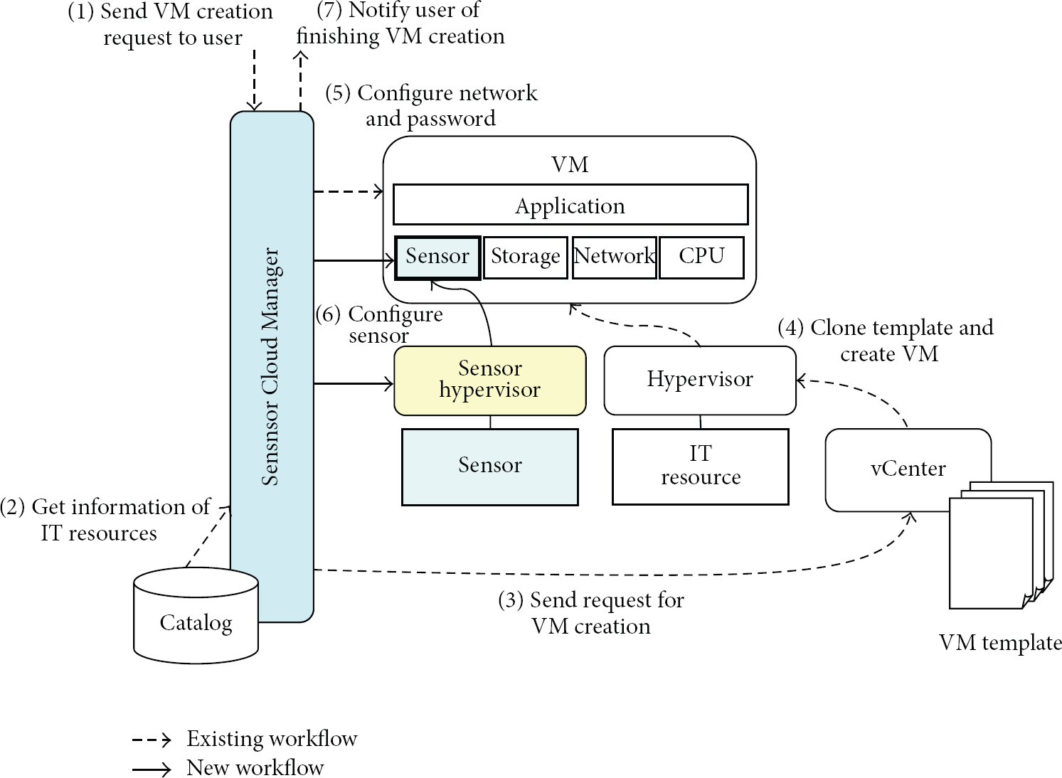
Workflow extensions of SC.
There is a workflow for SC Manager to delete the Virtual Sensor Devices from a VM based on an existing workflow when the user requests deprovisioning of the VM. When removing the Virtual Sensor Devices from the VM, SC Manager deletes the entry of each Virtual Sensor Device and the IP address of the deprovisioned VM from the table and requests to stop the data delivery to Data Forwarder. If no other VM is using this sensor device, then SC Manager stops the data delivery from this sensor device.
Before SC Manager registers the sensor devices with SC as IT resources, the administrator installs the Sensor Driver. SC Manager notifies Data Forwarder of the registration of the new sensor device and sends the information about it (e.g., IP address, port number) when the administrators request the registration of the new sensor device in SC. Data Forwarder loads the Sensor Driver for the registered sensor device to test the connection with that sensor device. After the connection test is successful, SC Manager adds the information about the sensor device to the catalog.
4.3. Standardization
SC Manager holds the information about the registered sensor devices as IT resources in its catalog. This catalog is referred to and updated when SC Manager provisions the VM. A standard catalog has information about typical IT resources, such as the number of CPUs, the amount of memory, and hard disk. Users can refer to this catalog to configure these IT resources for provisioning the VM. This catalog also has a template including an OS and any required software. Users can easily create a VM with the configured OS and software by allocating IT resources to this template in the catalog. This feature of the cloud computing is called “standardization.” We adopt this function to the sensor devices. The catalog of SC has the information about the sensor devices and the mapping between the standard template and the grouped sensor devices in Figure 1. The administrator can group the sensor devices by arbitrary categories, such as the same location, type, or sensed data. When users select the template and provision the VM, the grouped sensor devices can be allocated to the VM.
We extend this catalog to hold the information about the sensor device in SC. The owners of sensor devices send XML files to the administrator of SC to report on the information about own sensor devices. The administrator of SC adds the information to the catalog and tests the connections to these reported sensor devices. If the connection test succeeds, then the administrator maps the template and the grouped sensor devices. The users can use these sensor devices from the catalog as IT resources. The users select the template with the required sensor devices from the catalog in the same way as CPUs, memory, and storage when they want to provision the VM. We have added a new menu to the exiting catalog for the users to select the required sensor devices from this catalog. User can provision the same configured VMs with the sensor devices and software by the selecting the template.
4.4. Metering of Sensor Device Usage
Metering System for SC calculates the usage fees for the sensor devices and generates invoices for the users. The standard Metering System for the cloud computing records the usage of the IT resources such as CPUs, storage, and memory to calculate the usage fees. We have added a new function to the original Metering System to calculate the usage fees for sensor devices in SC. This Metering System collects the information about the usage of the sensor devices such as the number of transmitted bytes for the sensor data, the number of sensor devices, and the period of use. Figure 1 shows the system architecture of the Metering System for SC. We added a module to the existing Metering System to collect and report information about the usage of the sensor devices. This Metering System can calculate the usage fees of the sensor devices from the information with the fee policies of the sensor devices.
These are the steps of Metering System for SC. (1) Data Forwarder logs the amount of transmitted sensor data. These log files are periodically collected and sent to Metering System. (2) Metering System converts the received log files to the defined data formats to calculate the usage fees of the sensor devices for each user's account on the basis of the defined fee policies such as the price per unit of sensor data. (3) Metering System generates the invoices and the graphs from the information when the administrators and users request the information about the usage fee of the sensor devices by the Web-based GUI. (4) The DB for Metering System retains the converted log files and the invoices. The standard Metering System processes from steps (1) to (4). We have added the operation of sending log files to Data Forwarder to step (1) and the operation of configuring the usage fee policy of the sensor devices to step (2).
4.5. Monitoring of Sensor Device
The Monitoring System for SC monitors the status of the registered sensor devices. To detect any unusual behavior of the sensor devices, this system verifies the behaviors of the sensor such as sending the sensor data periodically, the replies to keep alive messages, the battery charge, and the transmission delay of the sensor data between Data Forwarder and the VM. The information about these events is collected from the Sensor Drivers and Data Forwarder.
Figure 1 shows the architecture of Monitoring System. This Monitoring System can monitor the behavior of the sensor devices as well as the typical IT resources in SC. We installed a new agent in a host on which a hypervisor for sensor devices is running. This agent sends the information about the status of the sensor devices to the Monitoring System. Here is how the Monitoring System works: (1) The agent sends the log data from the Sensor Drivers and Data Forwarder to Monitoring System for the detection of abnormal behaviors in SC. (2) Monitoring System records the log data from the agent in the DB and verifies whether or not the behavior of the sensor devices is correct. (3) The administrators check this information in the DB with a Web Portal GUI. (4) The administrators define the rules such the acceptable delay of the data transmission between Sensor Driver and Virtual Sensor Device. When Monitoring System detects anomalous behaviors from the log files by using the rules, then the Monitoring System notifies the administrator of this unusual behavior. The standard Monitoring System executes these processes from steps (1) to (4). To implement Monitoring System for SC, we have added the new configuration to the standard system to monitor the sensor devices in SC.
5. Implementation
We implemented SC including Metering and Monitoring Systems in the actual environments. We used electric power meters which can report on the consumed power using SNMP as the sensor device. This consumed electric power meter sends SNMP reply including the power at 8 outlets. Figure 4 shows this implementation environment. We installed SC Manager, Monitoring System, and Metering System on Host1. SC Manager provisions 5 VMs from VM2 to VM6 with the Virtual Sensor Devices on Host2. The users can access these VMs. Data Forwarder including the hypervisor for the sensor devices and Sensor Driver is installed in VM1 on Host2. We set up 5 power meters connected to physical 12 servers to measure the power consumed in this environment. We implemented Management, Monitoring, and Metering System for the sensor devices in Section 4 based on the standard software for the cloud computing.

Implementation environment.
Management of Sensor Devices. We use the existing software of the management of cloud environment [14] to implement sensor Management System. The new workflow for the sensor management is added to the existing workflow of this software. We also added the new entries to hold information about the sensor devices and networks in a DB that has the information about the other IT resources and the provisioned VMs. The hypervisor for sensor devices runs on the VM provisioned by Sensor Cloud Manager. We also implemented Sensor Driver to support SNMP. Data Forwarder sends the received sensor data from the sensor devices to the appropriate VMs. After SC Manager provisions the new VM and updates the XML configuration files for the hypervisor, the hypervisor reloads the XML files to prepare to send the required sensor data to the new VM.
Metering System. Metering System for SC is based on the existing metering system [15] as the base metering system for Normal Cloud computing. We added the new functions to calculate the usage fees for the sensor devices to this software. It can calculate not only the usage fees of the standard IT resources in the cloud but also any usage fees based on the log files and the fee policies. We added the new configuration data about the log data format from Data Forwarder and the new fee policies for each kind of sensor data.
Monitoring System. Monitoring System for SC is based on the existing Monitoring System [16] as the base software to monitor the normal IT resources of cloud computing systems. This software can monitor not only the normal IT resources but also any resources by using the definitions of the log data formats. Here, the electric power meters use SNMP packets to report the power consumption. Therefore, we added the new data format definition for the SNMP requests and replies to monitor the sensor devices on this software. We also added the new rules to detect the anomalous behaviors; for example, the sensor devices do not respond to keep alive messages.
6. Evaluation
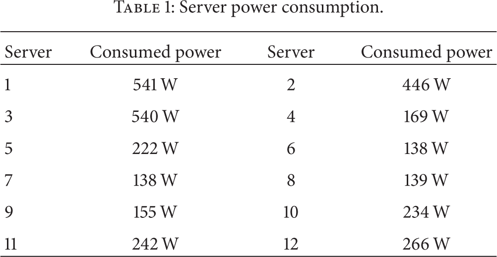
To evaluate SC, we acquired the power data from the five electric power meters connecting to twelve servers in the VM2 which is provisioned by SC on Host2. SC allows the users to acquire the sensor data from the appropriated sensor devices by using a Virtual Sensor Device on VM2. SC uses these power meter sensors as the active sensor because the sensor devices have an active AC line and a wired network.
Table 1 shows the power consumption data collected in VM2. The users can acquire all of the required sensor data by calling the API of the virtual sensor devices in SC.
Server power consumption.
6.1. Management of Sensor Devices
We evaluated the hypervisor that virtualizes the sensor devices for multiple users to share some sensor devices at the same time in SC. The electric power meters use SNMP to report the power consumption information in this evaluation environment. SC has two methods to receive the sensor data for the VM's users: asynchronous and synchronous communication. Figure 5 and Algorithm 1 show the processing of SNMP requests and replies in SC. (1) The hypervisor for sensor devices sends SNMP requests at the time intervals defined by the administrator and forwards the received power consumption data to the VM. This SNMP request asks for the sensor data from all 8-outlet power of the electric power meter at one time. (2) When the Virtual Sensor Device in VM receives the sensor data, it caches this data locally. If the users request the sensor data to the Virtual Sensor Device, it returns the sensor data to the users from the local cache. We call this reply method of data acquisition “asynchronous communication.” (3) Otherwise, the Virtual Sensor Device sends each data request to the hypervisor for the sensor devices explicitly if the sensor data in the local cache is too old when users request the sensor data. (4) When the hypervisor receives a data request from Virtual Sensor Device, this module immediately sends an SNMP request for the sensor data unless there is a pending request. This SNMP requests only the one data of one outlet's power consumption. When the hypervisor receives the sensor data, it forwards the data to all of the VMs that requests this sensor data. The Virtual Sensor Device sends this received sensor data to the users. We call this method of the sensor data acquisition “synchronous communication.” We also created a generic cloud computing environment called “Normal Cloud (NC)” in which the user directly connects to the sensor device to acquire sensor data in a VM. The VM sends SNMP request directly to the sensor devices. We have evaluated SC and Normal Cloud with one electrical power meter and changed the number of user's VM from one to five.
<Asynchronous> (1) Each period Tp: Send SNMP Request (All Sensors); Receive SNMP Reply (All Sensors); Send Sensor Data (VMs); <Synchronous> (4) Receive Synchronous Request (Data) Sensor = Get Sensor Device (Data) Send SNMP Request (Sensor) Receive SNMP Reply (Sensor) Send Sensor Data (VMs);
When sensor data is received from Hypervisor: (2) Store in Cache (Data); When sensor data is requested from API: Retrieve from Cache (Data); (2) (3) If Data is older than expire date Te (3) Send Synchronous Request (Data); Data = Receive Synchronous Reply();
Return Data; else (2)
Return Data;

Evaluation measurement.
First, we changed the request intervals and caching periods for the sensor data in the VM to evaluate the sensor transmission delay. Tp is the interval for the hypervisor to send an SNMP request in Algorithm 1. This time is equal to the interval of sending the requests for sensor data from the users to the Virtual Sensor Devices. We measured the delay of asynchronous communications when the users requested the sensor data and received it from the cache in the Virtual Sensor Device (
Figures 6 and 7 show the averages of the delay between sending the sensor data requests from the VMs and receiving 80 replies in SC. We set the interval time for sending the requests (Tp) to 500 msec in Figure 6 and 3 sec in Figure 7. The users request the sensor data from the Virtual Sensor Device every Tp. The X- and Y-axes of the graphs show the number of VMs and the delays between sending the requests and receiving the sensor data (

Comparison between delay for transmitting sensor data and cache time out in SC (data request time is 500 msec).

Comparison between delay for transmitting sensor data and cache time out in SC (data request time is 3 sec).
When Te is 250 msec in Figure 6 and 1.5 msec in Figure 7, the delays were 305 msec and 93 msec because synchronous communication occurs often. In SC, the transmission delay of more than two VMs is smaller than that of one VM because synchronous communication of each VM decreases due to sharing of the sensor data from each synchronous communication with other VMs. When Te is 250 msec in Figure 6, the number of synchronous communications in each VM decreases along with the increasing of the number of VMs. For example, if the number of VMs is one, two, three, four, and five, the synchronous communication times are 922 times, 682 times, 597 times, 584 times, and 523 times in each VM, respectively. The delay of five VMs is 86% of one VM when Tp is 250 msec in Figure 6. If the Te is set to enough long, the synchronous communication rarely occurs. For example, the number of synchronous communication is only one time in 4 VMs when Te is 750 msec in Figure 6.
Figures 8 and 9 show the delay between sending the sensor data requests from the VMs and receiving 80 replies in NC and SC. The delay of SC is the best case for the previous experiments in Figures 6 and 7. When the number of VMs is five in NC, the delay in Figures 6 and 7 is 84 msec and 53 msec. These delays are much worse than four VMs because the discarding SNMP packets due to overflows of the SNMP receive buffer in the electric power meter causes SNMP timeouts frequently when all five VMs send SNMP requests to one electric power meter at the same time. For example, if the number of VMs is one, two, three, four, and five, the number of SNMP timeouts is 0 time, 0 time, 0 time, 0 time, and 7 times in each VM, respectively in Figure 8. When the number of VMs is five and Te is longer than Tp, the delay of SC in Figures 8 and 9 is up to 69 msec and 37 msec less than that of NC because synchronous communications do not occur in SC. We see that SC allows more users to share a sensor device compared with NC if the suitable Te and Tp are set.

Comparison delay for transmitting between SC and NC (data request time is 500 msec).

Comparison delay for transmitting between SC and NC (data request time is 3 msec).
6.2. Monitoring of Sensor Device
We evaluated the detection of unusual states of the sensor devices by Monitoring System. The interval for receiving sensor data, Tp, was set to one second. The sending and receiving times from SNMP were sent to Monitoring System. The rule to detect an abnormal status is that the delay of receiving SNMP replies increases to more than 3 seconds. If this situation occurs, Monitoring System shows alerts. To evaluate the detection of unusual status, we connected the electric power meters to the networks and started the asynchronous communication in SC. After the VM received the sensor data, we disconnected the electric power meters from the hypervisor for sensor devices so that VM1 could not receive any SNMP replies. Figure 10 shows the detection of the unusual status of the sensor devices. This screen capture shows the receiving time of the SNMP replies. Forwarder Module can receive SNMP reply every second when the electric power meter is connected to the network. When the meter is disconnected from the network, Monitoring System reports the failure status of the sensor devices because of the lack of SNMP replies. This evaluation shows that the Monitoring System can detect the unusual status of the sensor devices.

Screen capture of the Monitoring System GUI.
6.3. Metering of Sensor Device Usage
This subsection describes the evaluation of the Metering System in SC. We added the functions to calculate usage fees for the sensor devices to the existing Metering System. To calculate the usage fees for the sensor devices, Data Forwarder sends information about the IP address of the VM and the sensor devices, the timestamps when the sensor data was sent to the VM, and the types of sensor data to Metering System in SC. We set the usage fee of each sensor data at 1 yen in this evaluation. One sensor data is defined as the amount of the power consumption data from one outlet. Figure 11 shows a screen dump of an invoice with which the users can see a web browser in this Metering System. This invoice describes the sensor usage fee for each VM as one of the billed items. The usage fee for sensor devices is 22 yen (
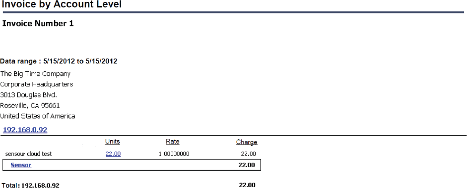
Screen capture of Metering System GUI.
6.4. Discussion
Section 6.1 describes the evaluation of the virtualization function of Management System. Figures 6 and 7 show that the delay increases by up to 260 msec and 83 msec, respectively, compared with the situation that Te is not enough long because synchronous communications occur frequently in SC. Thus, SC must control the amount of synchronous communication to avoid increases in the data transmission delay. Our hypervisor for sensor devices sends each SNMP request to each outlet when synchronous communications occur. If the sensor data of 8 outlets are requested, then 16 packets of SNMP requests and replies are generated as a total. To reduce the overhead for acquiring of sensor data, we need to improve the method to get sensor data by the hypervisor. For example, the hypervisor aggregates some SNMP requests into one request to reduce the number of SNMP requests.
The relation between the interval Tp that Data Forwarder periodically sends SNMP requests and the data retention period Te has a strong effect on the number of occurrences for synchronous communications. Te must be configured manually by the administrator in our implementation. In the future, we will add a function so that Te will be automatically configured to an optimal value with the interval Tp to minimize the synchronous communications.
This evaluation used only one sensor device and its transmission delay was small. When there are many sensor devices in SC, the transmission delay will increase because the loads of the data copies in Data Forwarder Module and the management of each VM's sessions will increase. Though our prototype implementation has one Data Forwarder module, we could design SC that has the multiple Data Forwarder modules to enhance the scalability of SC and distribute their workload. Moreover, this feature of the SC design can realize high availability. If the one Data Forwarder module becomes down, SC works correctly with other Data Forwarder modules. If the number of the sensor devices much increases, SC also increases the number of Data Forwarder modules to decrease the workload of the sensor data forwarding.
Users do not always obtain the real-time sensor data because the Data Forwarder module exists between the sensor devices and the users. In addition, SC often replies to the user's request for the sensor data from the local cache. An application that needs the strict real-time sensor data is not suitable for SC because the load of sensor devices would be greatly increased if SC discards the cache of sensor data at short intervals. However, common sensor applications allow small delay such as the agricultural monitoring, weather monitoring, and controls for air conditions or lighting. These applications are quite suitable in SC environment. Thus, SC can be adapted to almost all sensor applications.
7. Application
Figure 12 shows some applications that can make use of the features of SC. Multiple users and developers use various sensor devices that are at remote locations as virtual devices in one VM. They can share the same device by using the virtualizing function of SC. SC provides these capabilities. (1) The developers can create applications that adjust the status changes of sensor devices including the intermediate nodes. (2) The users can use the sensor applications and sensor devices easily. (3) They can provision some VMs that have the same sensor application with different sensor devices.

Application scenario for SC.
Figure 12 shows the two main kinds of sensor networks, home sensors and outdoor sensors. Sensor networks, A and B, are built by home sensors. One VM template has an application that manages an air conditioner with sensor devices of temperature and illumination in an outdoor location, and temperature, power, illumination, and motion in a home. If these are the same kinds of sensor devices, each user can provision a VM that has the application for A or B with the same template but with different sensor devices. Moreover, each application can also acquire the status of sensor devices to adapt to the changing status. For example, when the sampling ratio of illumination suddenly decreases because of low battery power, the middleware can hide the reduction in the frequency from the applications by interpolating the sensor data of illumination.
We show the process to provision the VMs when users require the security applications in Figure 12. (1) The user selects the parameters of the VM such as CPUs, storage, and the required sensor devices by using the GUI. (2) SC provisions the VM with the virtual sensor devices. (3) User runs the sensor applications with the virtual sensor devices in the provisioned VM. If the users want to run this security application only when they are not at home, they can use this application only during the required periods because they can dynamically provision and remove the VMs with the security application. The users save on the costs for the security applications and sensor devices if they only provision the VM and use the application only during the just required span.
8. Conclusion
We designed SC to manage the sensor devices as IT resources and share them in the same way as CPUs, storage, and memory. SC can not only virtualize the sensor devices to share them with multiple users, but also calculate the usage fee and monitor the sensor devices based on the existing systems of the standard cloud environment. We have implemented SC in actual servers and evaluated its virtualization functions. The evaluation results show that the transmission delays for sensor data in SC were decreased by up to 81% compared to the NC in which the users connected to the sensor devices directly, as long as the number of VM is more than five and the sensor data retention period for the cache is sufficiently long. SC allows multiple users to share the same sensor device at the same time. Here are some important futures we want to add: (1) support for multiple Data Forwarders to increase the scalability of the sensor devices; (2) increasing the kinds of sensor devices SC can support; (3) aggregating the sensor data requests from each VM and decreasing the number of sensor data requests; (4) automatic configuration of the optimal sensor data retention period for the cache based on the frequency of the sensor data requests from the users.
Footnotes
Conflict of Interests
The authors declare that they have no conflict of interests regarding the publication of this paper.