
Abstract
This paper analyzes flow mode magnetorheological (MR) dampers with an eccentric annular gap (i.e., a nonuniform annular gap). To this end, an MR damper analysis for an eccentric annular gap is constructed based on approximating the eccentric annular gap using a rectangular duct with a variable gap, as well as a Bingham-plastic constitutive model of the MR fluid. Performance of flow mode MR dampers with an eccentric gap was assessed analytically using both field-dependent damping force and damping coefficient, which is the ratio of equivalent viscous field-on damping to field-off damping. In addition, damper capabilities of flow mode MR dampers with an eccentric gap were compared to a concentric gap (i.e., uniform annular gap).
1. Introduction
Magnetorheological (MR) dampers are attractive semiactive energy dissipators because their stroking loads are continuously controllable by simply adjusting a current input to an electromagnet. Also, the response time is fast (a few milliseconds), and the required power consumption is low (tens of watts). As a result, MR dampers have been employed as vibration mitigation devices for a number of applications, such as seismic dampers [1–7], seat dampers [8–11], and vibration isolators [12–16]. More recently, MR dampers have been also applied to aerial and ground vehicles as crashworthiness devices, such as landing gear oleos [17–20], impact dampers [21–26], and energy absorbers [27–29].
Many studies of MR dampers have been conducted based on the flow mode of operation because, for a given MR damper yield force, the design is more compact (less active volume) than for a typical shear mode device. In flow mode MR dampers, MR fluid flows through an MR valve, which is typically configured as an annulus with two stationary walls and an electromagnetic coil to adjust the magnetic field input. During motion of the large area piston, the MR fluid flows through small area annular valve because of the induced pressure so that resistive damping force results. The damping force magnitude is continuously controllable by adjusting the intensity of the magnetic field input. Thus far, MR valves inside flow mode MR dampers have been designed so as to have a uniform gap configured as two concentric tubes. But the study of flow mode MR dampers with an eccentric gap (i.e., nonuniform gap configured as two eccentric tubes) has not much been examined. Moreover, to our knowledge, the analysis of flow mode MR dampers with an eccentric gap has not yet been explored. Therefore, in this study, the analysis of flow mode MR dampers with an eccentric gap is presented. First, an eccentric gap inside flow mode MR dampers was approximated as a rectangular duct or slit with variable height. A constitutive Bingham-plastic model was used in this study to represent MR fluid flow. Based on these assumptions, the analysis of flow mode MR dampers with an eccentric gap was constructed. The field-dependent damper force and the damping coefficient, which is the ratio of the equivalent viscous damping to the field-off damping, were theoretically obtained in terms of a nondimensional preyield or plug thickness. Finally, the performance of flow mode MR dampers with an eccentric gap was theoretically compared with that of MR dampers with a concentric gap (i.e., uniform gap).
2. Magnetorheological Dampers with an Eccentric Gap
Figure 1 presents the piston head of a flow mode MR damper with either a concentric gap or an eccentric gap. Note that, to simplify the analysis, the gas chamber typically used to compensate for the piston rod volume of single-ended dampers was neglected. In addition, the electromagnetic coil for activating an MR fluid in the annular duct was omitted in Figure 1. More detailed full scale MR damper configuration can be found in [14, 22, 27]. In Figure 1, y is the lateral coordinate originated from the bottom wall of the annular duct and x is the axial coordinate measured from the valve entrance. As seen in this figure, the gap of MR dampers with a concentric gap is uniform. But the gap of MR dampers with an eccentric gap is not uniform and varied with azimuth angle. The gap, d, of MR dampers with an eccentric gap can be obtained from Figure 2 as follows:

Here, e is the eccentric distance, R1 is the radius of the outer cylinder, R2 is the radius of the inner cylinder, and θ is the azimuth angle. Because
where c = R1 − R2 is the clearance.
Piston head of flow mode magnetorheological (MR) dampers with two different gaps.

Top view of the piston head of flow mode MR dampers with an eccentric gap.
3. Damper Analysis
The damper force, F, of flow mode MR dampers with an eccentric gap can be given by

Here, A p is the effective piston head area and ΔP is the pressure drop down the length of the MR valve. To simplify the analysis, the fluid flow in the MR valve is assumed to be laminar. Note that the assumption of this laminar flow holds for Reynolds number below turbulent transition, Re < 2000 [27]. Then, the pressure drop, ΔP, can be given by [30, 31]

Here, τ is the shear stress and L is the active length of the MR valve.
Integrating (4) with the following boundary conditions [30, 31]
yields the shear stress profile in the gap as follows:
Here, τ y is the average yield stress in the gap. y pi and y po are the bottom and top locations of the preyield region (defined as the region where the local shear stress is less than the yield stress), respectively. They are given as follows:

where δ is the preyield or plug thickness given by
Note that the yield stress varies with the nonconstant gap, and a magnetic field input is a function of the gap. To simplify the analysis, the average yield stress was used in this study. On the other hand, as seen in (7), if δ ≥ d(θ y ), the local gap d(θ) at θ ≥ θ y will be blocked. This physically implies that there is no fluid flow in the locally blocked gap, which would occur in the narrowest side of the eccentric gap. From this relationship and (2), the critical azimuth angle θ y can be found, in which the local gap will be blocked by the yield stress of an MR fluid as follows:

where
Here, ε is the eccentric ratio and

In this study, the shear stress characteristics of MR fluids were described by a constitutive Bingham-plastic model as follows:

Here, μ is the fluid viscosity of an MR fluid and u is the fluid velocity in the gap. Substituting (12) into (6) and integrating it with the boundary conditions [30, 31] (i.e., no slip conditions, velocity compatibility conditions, and velocity gradient compatibility conditions) yield the fluid velocity profiles as follows:

Here, the subscripts in (13) imply region 1 (i.e., postyield region where 0 ≤ y ≤ y pi ), region 2 (i.e., preyield region where y pi ≤ y ≤ y po ), and region 3 (i.e., postyield region where y po ≤ y ≤ d).
The flow rate in each region can be obtained by double integration of (13):

The total flow rate is then

where

4. Damping
The flow rate displaced by the piston head is equal to the total flow rate given in (15) as follows:

Here, V p is the piston velocity. From (3), (15)–(17), the damper force is obtained by

where

Here, Ceq is the equivalent viscous damping constant. The field-off damping constant C0 can be obtained by substituting

This leads to the expression for the damping coefficient (nondimensional), defined as the ratio of the equivalent viscous damping constant to the field-off damping constant as follows:

Equation (18) can be rearranged for a nonlinear root finding problem for the nondimensional preyield thickness as follows:

where the nondimensional Bingham number Bi is defined by

Given A
p
, Bi, and R2, the nondimensional preyield thickness
If ε = 0 and θ y = π (i.e., concentric case), (21) becomes

In addition, (22) becomes

Equations (24) and (25) are identical to the results in [30, 31].
5. Sample Analyses
To theoretically evaluate the damper performance of flow mode MR dampers with an eccentric gap, we chose the important damper parameters for one damper design case as follows:

Given (26), we can numerically solve (22) to obtain the nondimensional preyield thickness,
Figure 3 presents the damping coefficient of flow mode MR dampers with an eccentric gap versus the Bingham number. As seen in this figure, the damping coefficient increases, as the Bingham number increases. This physically implies that the controllable MR yield damper force (i.e., the force difference between the field-on damper force and the field-off damper force) increases as the applied current increases. But, compared to the concentric gap case (i.e., ε = 0), the increment of the eccentric ratio decreases the damping coefficient. This physically implies that, for a certain current input, flow mode MR dampers with an eccentric gap produce less controllable MR yield damper force than flow mode MR dampers with a concentric gap.

Damping coefficient of flow mode MR dampers with an eccentric gap versus the Bingham number.
Figure 4 presents the critical azimuth angle θ y versus the Bingham number. As seen in this figure, the critical azimuth angle for the concentric gap case is 180 degrees (i.e., the gap is fully open). But as the eccentric ratio increases, the critical azimuth angle becomes smaller. This physically implies that when the eccentric ratio increases, the locally blocked area in the gap increases.
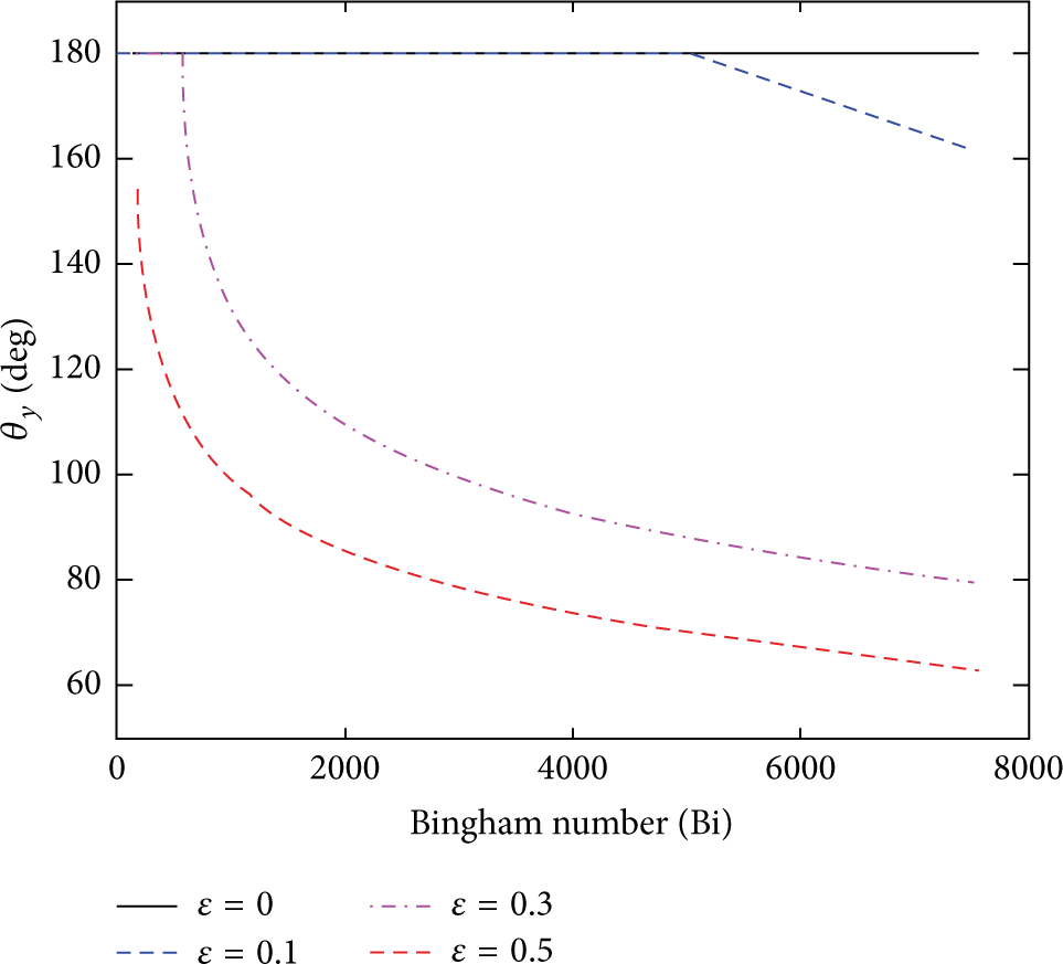
The critical azimuth angle versus the Bingham number.
Figure 5 presents the damper force of flow mode MR dampers with an eccentric gap versus the piston velocity. As seen in this figure, as the eccentric ratio increases, the field-off damper force decreases. This phenomenon can be also confirmed using (20). In (20), the field-off damping constant is inversely proportional to 1 + (3/2)ε2. This physically implies that the fluid resistance of the eccentric gap is smaller than that of the concentric gap. As a result, the field-off damper force for the eccentric gap case becomes smaller than that for the concentric gap case. On the other hand, for the field-on case also, the damper force decreases as the eccentric ratio increases. This phenomenon is expected from the trend of the damping coefficient shown in Figure 3.

Damper force of flow mode MR dampers with an eccentric gap versus the piston velocity.
Figure 6 presents the critical azimuth angle at field-on state versus the piston velocity. As seen in this figure, the locally blocked area in the gap increases as the eccentric ratio increases and the piston velocity decreases.

The critical azimuth angle at field-on state versus the piston velocity.
Figure 7 presents the comparison of fluid velocity profiles of flow mode MR dampers with respect to the eccentric gaps at the piston velocity of 0.1 m/s. As seen in this figure, for the concentric gap case, the fluid velocity in the gap is uniform. But, for the eccentric gap cases, the fluid velocity in the narrow size of the gap becomes smaller than the concentric gap case and the fluid velocity in the wide size of the gap becomes larger. Specially, for the eccentric ratio of ε = 0.5, the fluid velocity in the narrow size of the gap at τ y = 5 kPa becomes zero. This physically implies that the locally blocked area in the gap takes place.
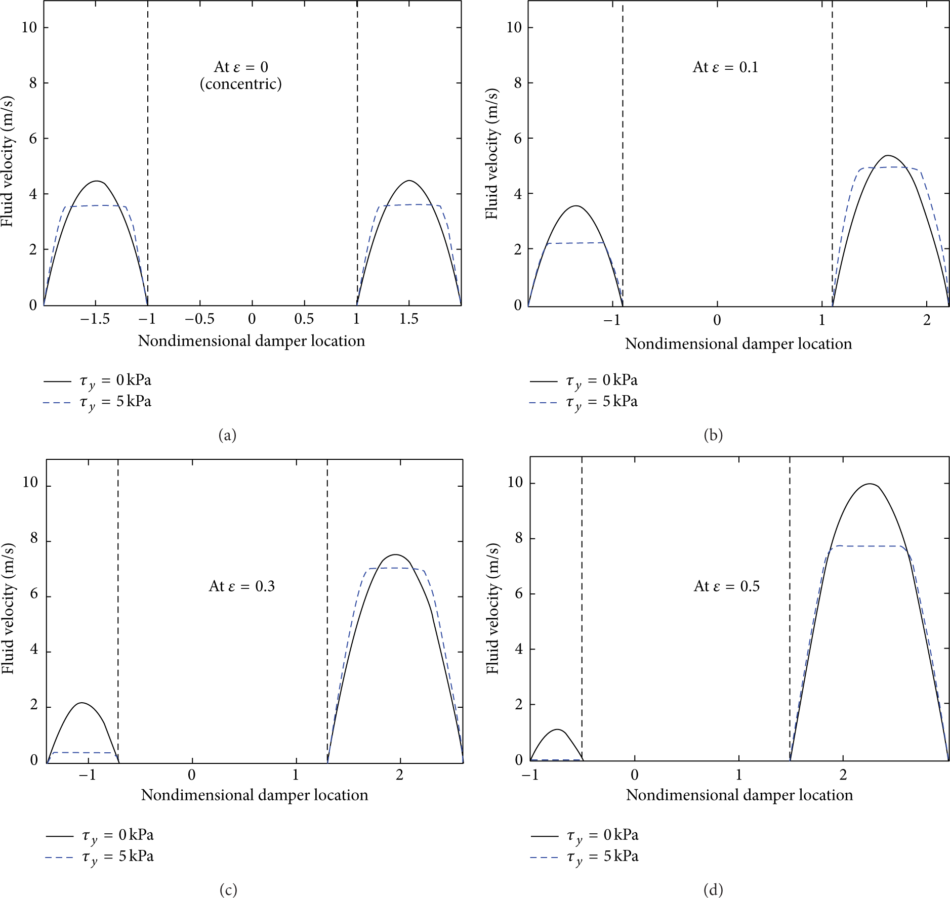
Comparison of fluid velocity profiles of flow mode MR dampers with respect to the eccentric gaps at the piston velocity of 0.1 m/s.
6. Conclusions
Analysis of flow mode magnetorheological (MR) dampers with an eccentric gap was presented in this study. To this end, an eccentric gap inside flow mode MR dampers was approximated by a rectangular duct or slit geometry with variable height, and a Bingham-plastic constitutive relationship was used for the MR fluid. The field-dependent damper force of flow mode MR dampers with an eccentric gap was theoretically obtained in terms of a nondimensional preyield thickness. Then, the damping coefficient, which is the ratio of the equivalent viscous damping constant to the field-off damping constant, was obtained. Using numerical analysis, it was analytically found that both damping coefficients decrease, and the critical azimuth angle also decreases, as the eccentric ratio increases. In addition, it was observed that the field-off and field-on damper forces of flow mode MR dampers with an eccentric gap become smaller than those of the concentric gap case. In future work, the analytical methodology developed in this study should be experimentally validated.
Conflict of Interests
The authors declare that there is no conflict of interests regarding the publication of this paper.