
Abstract
Thermal performance analysis for laminar forced convection in an isothermal wall square channel with 30° V-baffle is presented numerically. The parameters of the V-baffle, blockage ratio (b/H, BR), pitch ratio (P/H, PR), flow direction (V-Downstream and V-Upstream), and arrangement (in-line and staggered), are studied and compared with the previous works, 20° and 45° V-baffle. The Reynolds number based on the hydraulic diameter of the channel (D h ), Re = 100–2000, is used in range study. The results show that the flow configurations of 30° V-baffle are found similar as 20° and 45° V-baffle. The fully developed periodic flow and heat transfer are created around 7th-8th module, while the periodic flow and heat transfer profiles are found at 2nd module in all cases. Except for the periodic concept, the 30° V-baffle can help to reduce the pressure loss around 2.3 times in comparison with the 45° V-baffle at the maximum f/f0 value (BR = 0.3, PR = 1, V-Downstream). The optimum thermal enhancement factor for the 30° V-baffle is found around 4.25 at BR = 0.15, PR = 1, and Re = 2000 for V-Downstream case with in-line arrangement.
1. Introduction
The baffles or thin rib vortex generators are extensively used for augmenting heat transfer in heat exchangers. The effects of the baffled shape, inclined, V-shaped, modified V-shaped, and so forth, on flow conFigurations and heat transfer behaviors have been studied on both experimental and numerical methods. The numerical method can help to describe the flow structure occurring in the baffled channel and also help to reduce the time and cost for the investigation when compared with the experimental method. The numerical investigations for the baffle vortex generators in square channels with different parameters are shown in Table 1.
Literature reviews.

Except for V-baffles and inclined baffles, the literature reviews for the investigations of various type vortex generators and modified V-shaped vortex generators have been reported. For example, Alam et al. [1] studied the effects of perforation holes in the V-shaped blockages on thermal performances for a solar air heater channel. They found that the vortex generators give the Nusselt number around 1.13 times higher than the smooth channel. Alam et al. [2] also investigated the heat transfer augmentation of the solar air heater channel fitted with V-shaped perforated blocks. They reported that the enhancements are around 6.76 and 28.84 times higher than the smooth channel for the Nusselt number and friction loss, respectively. Karwa and Chitoshiya [3] experimentally investigated the influences of 60° V-Downstream discrete ribs placed on an absorber plate in a channel. They summarized that the thermal performance is around 12.5–20%. Lotfi et al. [4] studied the use of various type vortex generators in a wavy fin-and-tube heat exchanger with numerical method. Zhou and Feng [5] reported the enhancement of heat transfer with using plane and curved winglet vortex generators with punched holes. They found that the use of curved winglet vortex generators is better than the plane winglet vortex generators when considering both heat transfer and pressure loss. Chen et al. [14] studied the effects of longitudinal vortex generators in a rectangular microchannel on flow configurations and heat transfer characteristics. They presented that the augmentations in heat transfer are around 12.3–73.8% and 3.4–45.4% for aspect ratios of 0.0667 and 0.25, respectively. Du et al. [15] studied the use of longitudinal vortex generators in a wavy fin-and-tube heat exchanger on thermal performances. They concluded that the enhancements of the Nusselt number and friction factor are found to be around 21–60% and 13–83%, respectively.
As the previous works, it is found that the two sides of the baffles give higher heat transfer rate and the thermal performance than only one side baffle as [6, 7]. The references [10, 11] show that the V-shaped baffle performs higher heat transfer and thermal enhancement factor than the inclined-baffle at the same conditions. Except for baffled shape, it is found that flow attack angles are important key for heat transfer augmentation. For the V-baffles, the flow attack angle of 20° has a prominent point for reducing the pressure loss and gives better heat transfer distributions over the channel walls while the specific point for the 45° is the augmenting heat transfer but also gives very enlarge pressure loss. The numerical investigations for the 20° and 45° V-baffles on both the upper and lower walls were presented while the study for 30° V-baffle placed on both the upper and lower walls of the square channel has rarely been reported. Therefore, this work focuses on the numerical investigations for the 30° V-baffle placed on both the upper and lower walls of the square channel. The parameters, blockage ratios, pitch ratios, Reynolds numbers, flow directions, and arrangements, are investigated numerically in three dimensions. The periodic concepts on both flow structure and heat transfer are also studied. The numerical results are compared with the smooth square channel and the previous works: the 20° and 45° V-baffles. The empirical correlations and optimization for the 30° V-baffle are presented to help to create the compact heat exchanger square channel in the heating system.
2. Flow Descriptions
2.1. Baffle Geometry and Case Studies
The configuration of 30° V-baffles in a square channel is referred to from [11, 12]. The 30° V-baffles are placed on both the upper and lower walls of the square channel with in-line and staggered arrangements as in Figures 1(a) and 1(b), respectively. The computational domains for in-line and staggered arrangements are presented in Figures 2(a) and 2(b), respectively. The air enters the square channel at an inlet temperature, Tin, and flows over the 30° V-baffles where b is the baffle height, H set to 0.05 m is the square channel height, and b/H is known as the blockage ratio, BR. The axial pitch, L, or distance between the baffle cell is set to L = H in which L/H is defined as the pitch spacing ratio, PR. The ranges studied are shown in Table 2.
Case studies.

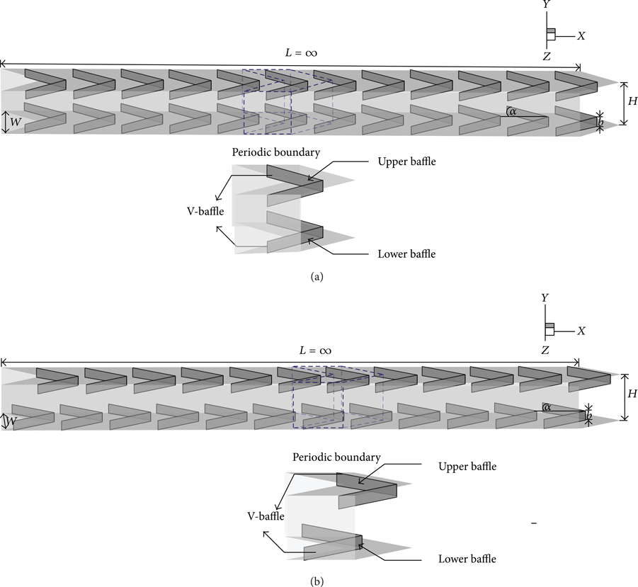
The square channel with 30° V-baffles on both the upper and lower walls for (a) in-line and (b) staggered arrangement.

Computational domain of 30° V-baffles for (a) in-line and (b) staggered arrangement.
2.2. Boundary Conditions
The boundary conditions of the present work are cited form [11, 12] for the periodic module. The summary of the boundary conditions is as shown in Table 3. For a full length V-baffled channel, a uniform air velocity, u0, is introduced at the inlet while a pressure outlet condition is applied at the exit regime.
Boundary conditions for the periodic module.

3. Mathematical Foundation
From [11, 12], the numerical models for fluid flow and heat transfer in a square channel are developed under the following assumptions:
steady three-dimensional fluid flow and heat transfer,
the flow being laminar and incompressible,
constant fluid properties,
body forces and viscous dissipation being ignored,
negligible radiation heat transfer.
Based on the assumptions, the channel flow is governed by the continuity, the Navier-Stokes equations, and the energy equation. In the Cartesian tensor form these equations can be written as follows:
continuity equation:

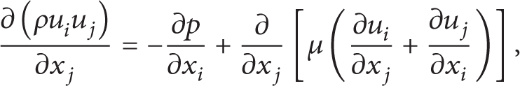
momentum equation:
energy equation:
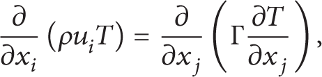
where Γ is the thermal diffusivity and is given by

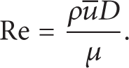
Apart from the energy equation discretized by the QUICK scheme, the governing equations were discretized by the second order upwind scheme, decoupling with the SIMPLE algorithm, and solved using a finite volume approach [16]. The solutions were considered to be converged when the normalized residual values were less than 10−5 for all variables but less than 10−9 only for the energy equation. Four parameters of interest in the present work are the Reynolds number, friction factor, Nusselt number, and thermal enhancement factor. The Reynolds number is defined as
The friction factor f is computed by pressure drop Δp across the length of the periodic channel L as

The heat transfer is measured by the local Nusselt number which can be written as
The average Nusselt number can be obtained by

The thermal enhancement factor (η) is defined as the ratio of the heat transfer coefficient of an augmented surface h to that of a smooth surface, h0, at an equal pumping power and given by

where Nu0 and f0 stand for Nusselt number and friction factor for the smooth square channel, respectively.
The computational domain is resolved by regular Cartesian elements. For this channel flow, however, regular grid was applied throughout the domain. A grid independence procedure was implemented by using Richardson extrapolation technique over grids with different numbers of cells. The characteristics of four grids, 52,200, 84,000, 120, 400, and 240,000 cells, are used in the simulations for using the grid convergence index (GCI) [17]. The variation in Nu and f values for the 30° in-line V-baffles at BR = 0.15 and Re = 1000 is less than 0.25% when increasing the number of cells from 120,400 to 240,000; thus there is no such advantage in increasing the number of cells beyond this value. Considering both convergent time and solution precision, the grid system of 120,400 cells was adopted for the current computational model.
For visualization of vortices in three-dimensional flows, the coherent structure detecting method based on the λ2-criterion of Jeong and Hussain [18] is introduced in the current study. In this method, a vortex is defined as a region where the second eigenvalue, λ2, of the symmetric tensor S ij S ji + U ij U ji is negative. The tensors S ij and U ij are the symmetric and antisymmetric parts of the velocity gradient tensor or called the rate of strain tensor and vorticity tensor, respectively, and have the form as follows:

A rotating structure can be raised to view as an “iso-surface” of constant λ2, where λ2 is realized.
4. Result and Discussion
4.1. Verification of Smooth Tube
The validations of the heat transfer and friction factor for the smooth square channel are done by comparing the present values with the previous values under a similar operating condition. The results are found to be in excellent agreement with exact solution values obtained from the open literature [19] for both the Nusselt number and friction factor, less than ±0.25% deviation. The exact solutions of the Nusselt number and friction factor for laminar flows over the smooth square channel with constant wall temperature are as follows [19]:
4.2. Fully Developed Periodic Descriptions
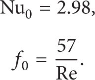
The periodic concepts for the in-line 30° V-baffle on both flow structure and heat transfer behavior are presented in Figures 3–7. Figures 3(a) and 3(b) show the axial distributions of Nu x /Nu0 and u/u0 at various locations for BR = 0.2, PR = 1, and Re = 1000, respectively. As seen, the periodic flow and heat transfer profiles are found around 2nd–3rd module and the fully developed periodic flow configurations and heat transfer behaviors are appearing on the 7th–8th module. The heat transfer and flow profiles in terms of Nu x /Nu0 and u/u0, respectively, on the full length square channel and the periodic module are found to be similar in range of the fully developed periodic zone.
Axial distributions of (a) Nu x /Nu0 and (b) u/u0 at various locations for BR = 0.2, PR = 1, and Re = 1000.

Axial distributions of u/u0 at various y/D.

Axial distributions of u/u0 at various Re.
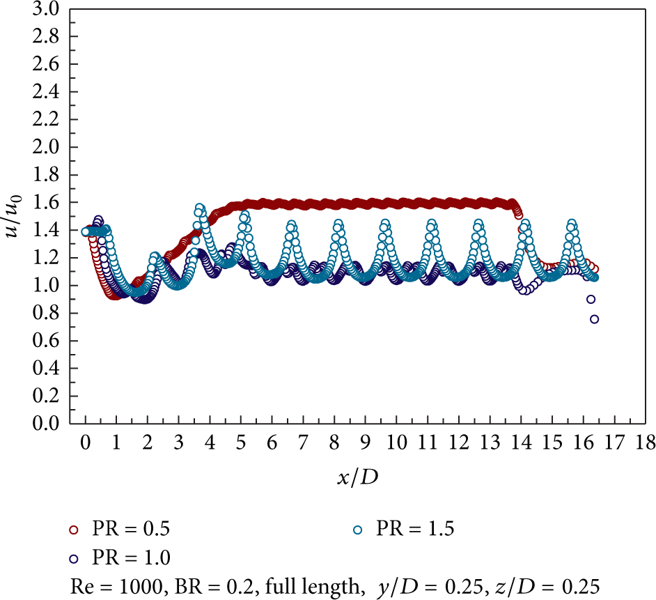
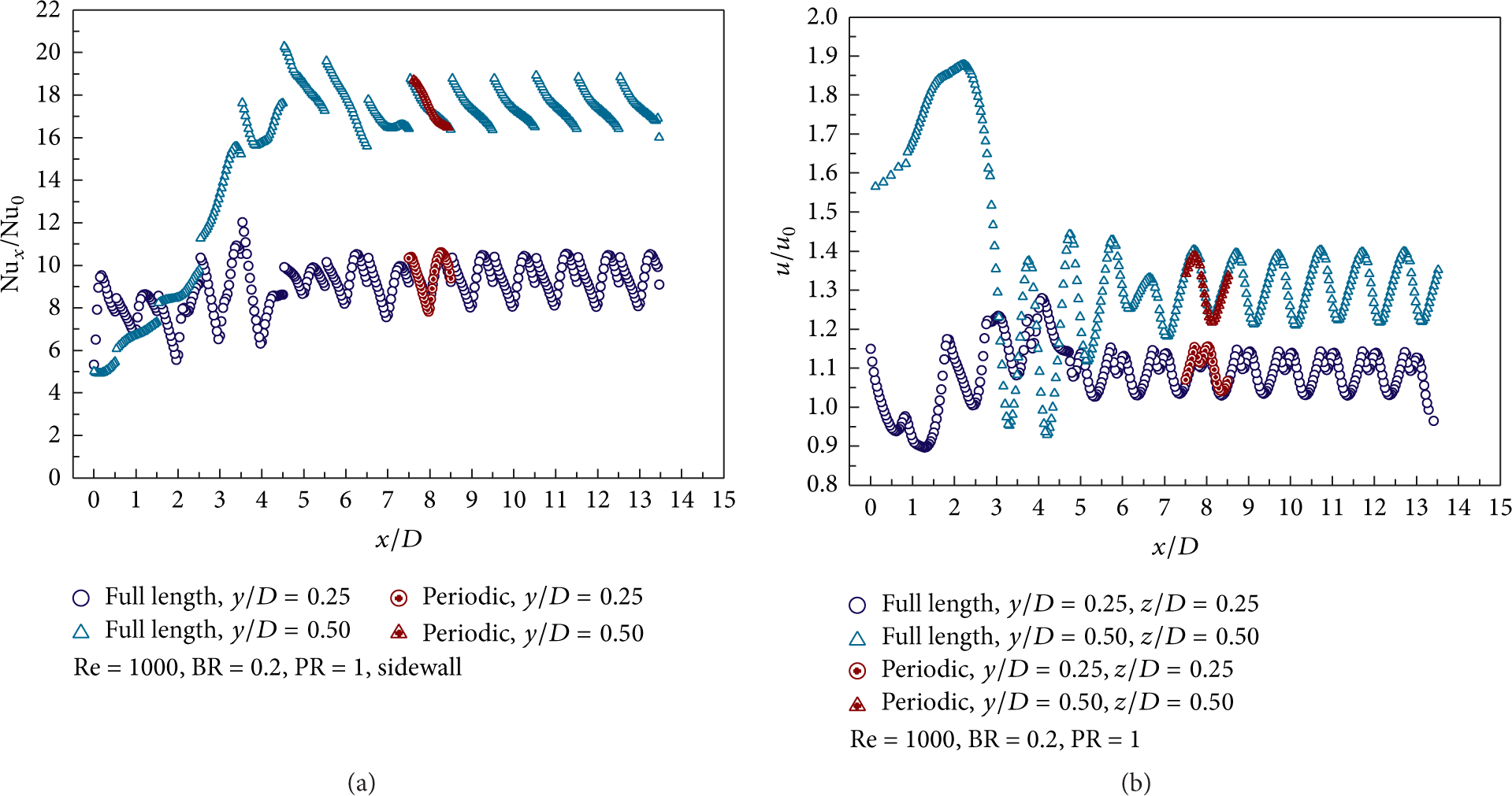
Axial distributions of u/u0 at various PR.

Axial distributions of u/u0 at various BR.
The influences of the position in y-axis for the periodic flow structure are presented in Figure 4 for Re = 1000, BR = 0.2, and PR = 1 at z/D = 0.25. The fully developed periodic flow profiles for the y/D = 0.125 appear faster than the y/D = 0.25 and 0.5.
The effects of Reynolds number, pitch ratio, and blockage ratio for the occurring fully developed periodic flow profile are presented in Figures 5, 6, and 7, respectively. In addition, the fully developed periodic flow profiles perform faster when rising Re, BR and reducing PR.
4.3. Flow Topology
The flow configurations and heat transfer behaviors of the 30° V-baffle are found similar as the 20° and 45° V-baffle [11, 12]. Therefore, the current study will present the flow structure of the 30° V-baffle in terms of coherent structure, iso-surface of λ2 with velocity vector for BR = 0.2, PR = 1, and Re = 1000 as in Figures 8(a) and 8(b), respectively, for in-line and staggered arrangement, while the streamlines in transverse planes, contour temperature, contour Nu x , and streamlines impinging jet on the channel walls can be seen as in [11, 12]. In general, the 30° V-baffles create four main vortex flows and four small vortices at the corner of the square channel. Considering the lower part of the vortex flow, the 30° V-baffles produce the counter-rotating flow with common-flow-up. The center of the vortex flow is found to be changed depending on the position of the V-baffle. The vortex flows are not complete within one module. The flow profiles repeat itself from one to another module. The general flow structure of V-Upstream is found nearly pattern as V-Downstream with reverse rotation; counter rotating flow with common-flow-down.
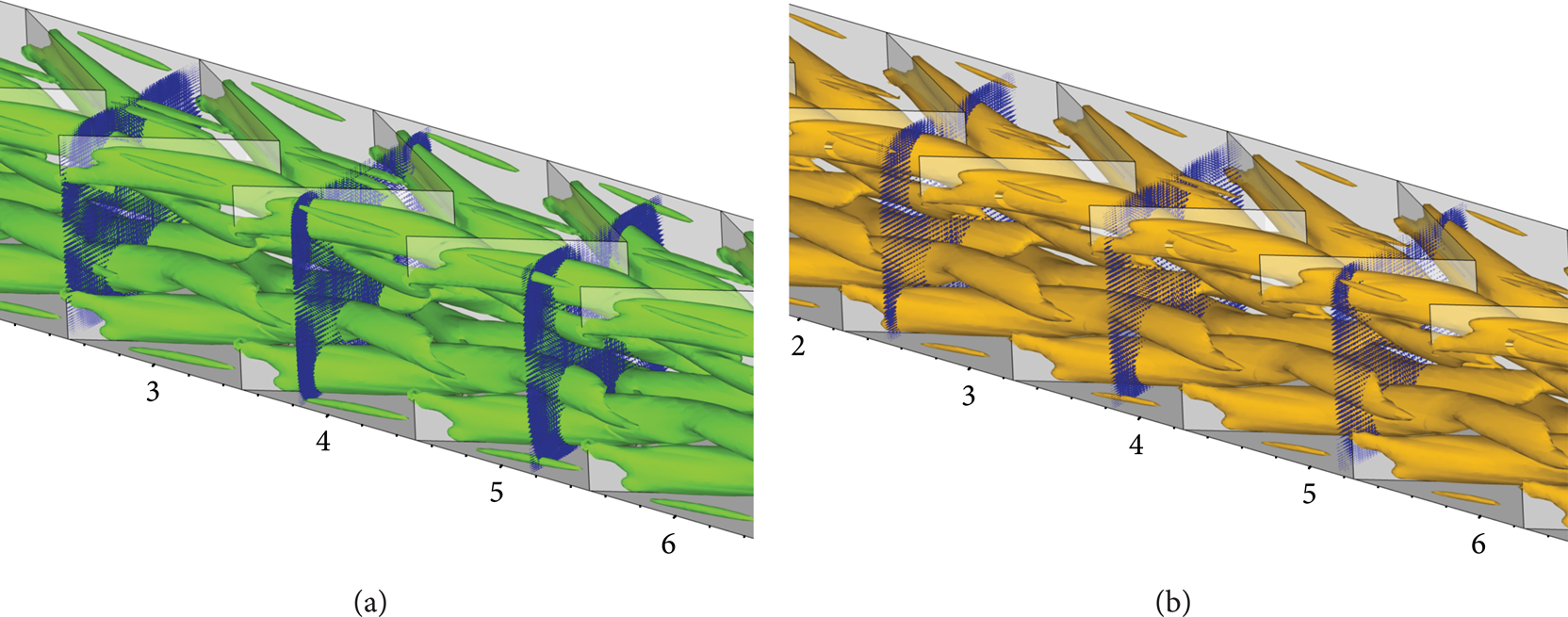
Iso-surface of λ2 with velocity vector for V-baffles, (a) in-line and (b) staggered, at BR = 0.2, PR = 1, and Re = 1000.
4.4. Effect of V-Baffle Arrangement
The influences of arrangement for the 30° V-baffle placed on both the upper and lower walls of the square channel are presented in terms of the variations of Nu/Nu0, f/f0, and η as in Figures 9, 10, and 11, respectively. As seen in the figures, it is found that in-line case shows higher heat transfer rate than the staggered case when BR ≤ 0.2. At BR = 0.30, the in-line case gives slightly lower friction factor than the staggered case. The optimum thermal enhancement factor is around 4.25 for in-line arrangement.

The variations of the Nu/Nu0 for 30° V-baffle with various arrangements: (a) V-Downstream and (b) V-Upstream.
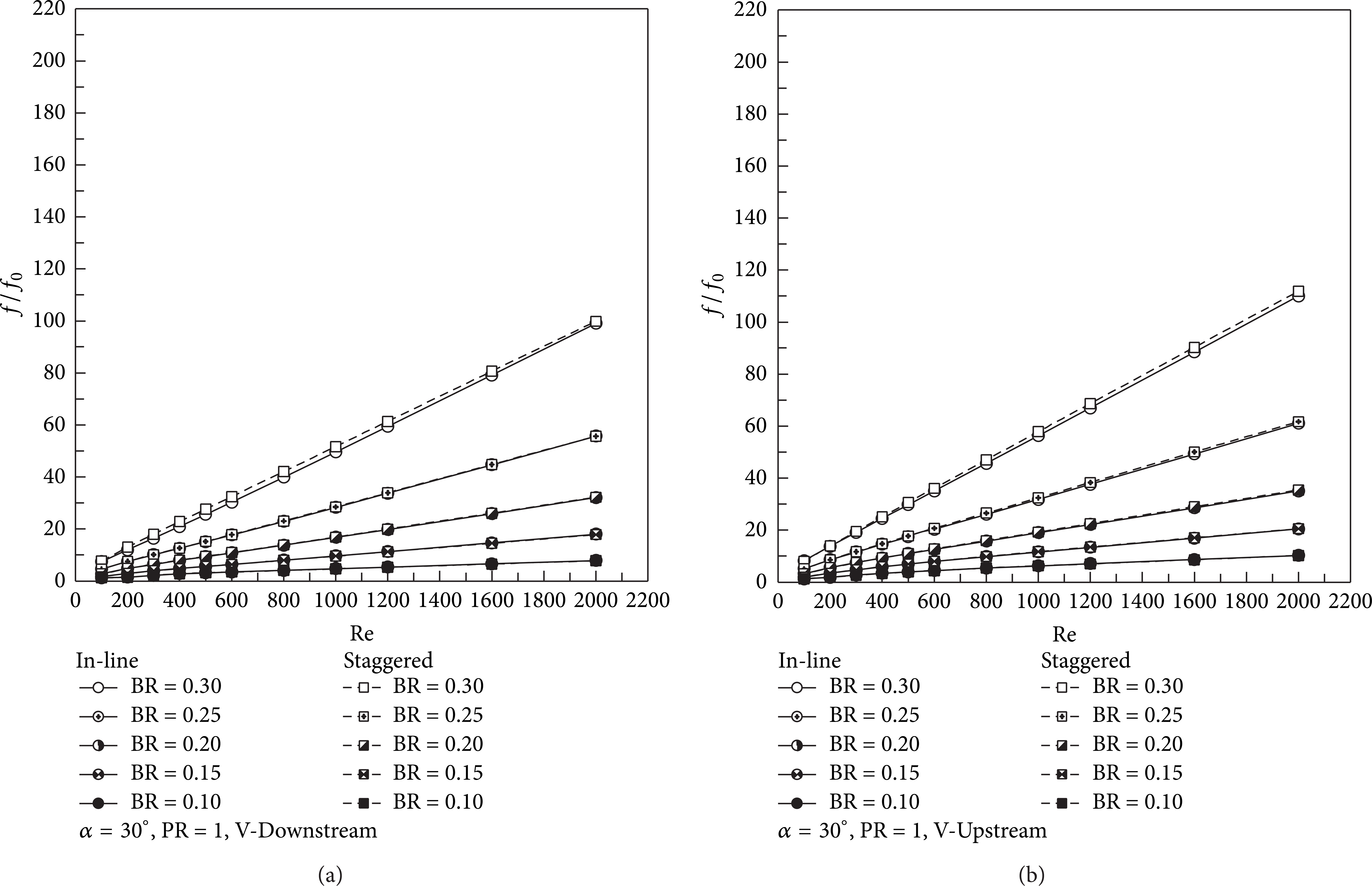
The variations of the f/f0 for 30° V-baffle with various arrangements: (a) V-Downstream and (b) V-Upstream.
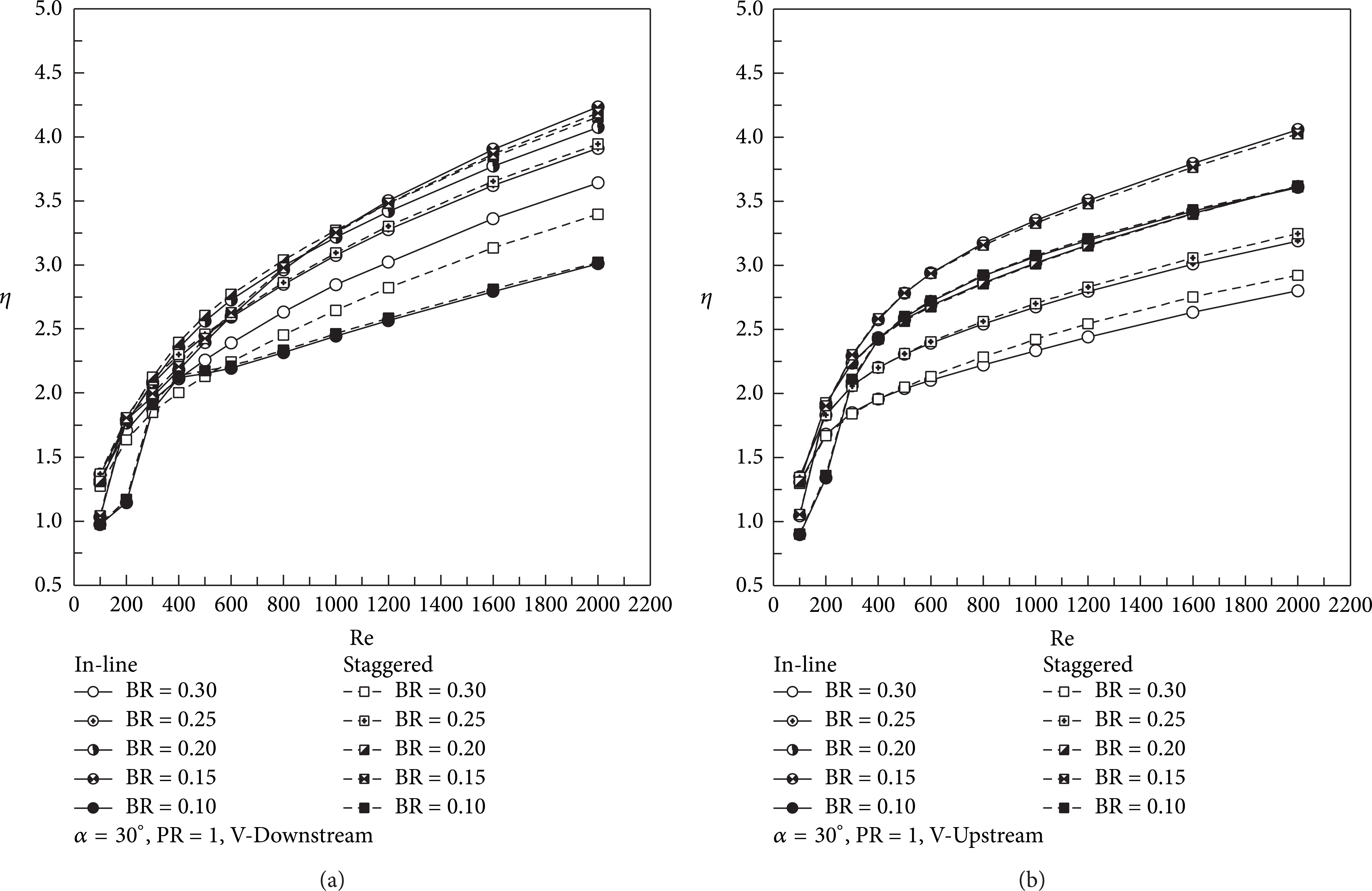
The variations of the η for 30° V-baffle with various arrangements: (a) V-Downstream and (b) V-Upstream.
4.5. Effect of Blockage Ratio
The effects of blockage ratio in square channel are displayed by considering the variations of Nu/Nu0, f/f0, and η with BR values in Figures 12, 13, and 14, respectively, at various Reynolds number and also compared with the previous work, 20° and 45° V-baffle [11, 12], for in-line arrangement only. As figures, it is found that the increasing BR values lead to the rise of the Nu/Nu0 and f/f0 for all flow attack angles, especially the BR = 0.30 which provides the highest on both Nu/Nu0 and f/f0 values. The peak of heat transfer enhancement is found in range 0.10 < BR < 0.15 while the maximum friction factor appears at BR = 0.25–0.30. As the results on both heat transfer and friction factor, the thermal enhancement factor is found to be the maximum point at range 0.15 < BR < 0.20. This means that the range 0.15 < BR < 0.20 performs the optimization between the increasing of the heat transfer rate and the rise-up of the friction factor in the system for V-baffles square channel.
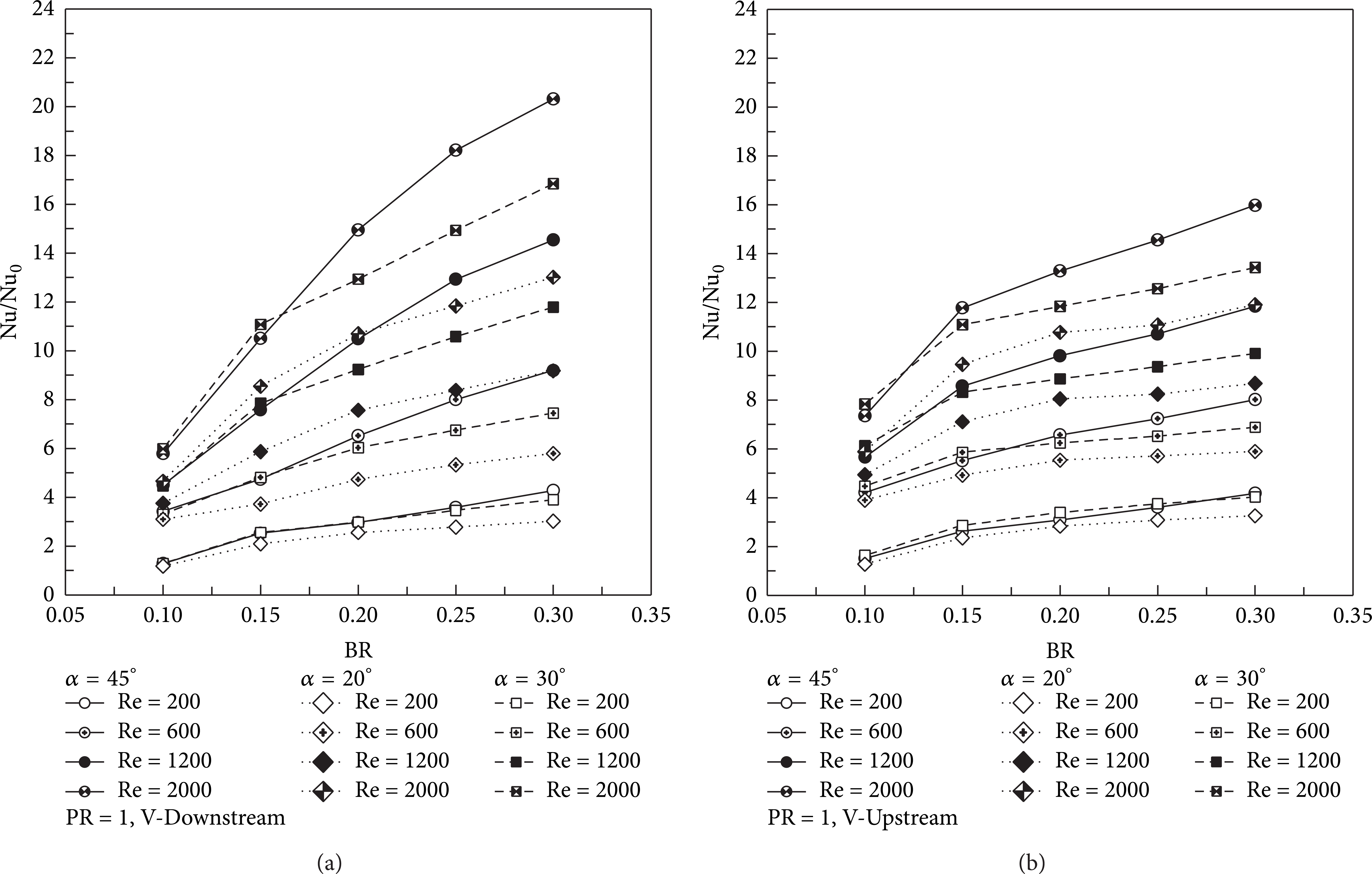
The variations of the Nu/Nu0 for 30° V-baffle with BR at various α and Re values: (a) V-Downstream and (b) V-Upstream.

The variations of the f/f0 for 30° V-baffle with BR at various α and Re values: (a) V-Downstream and (b) V-Upstream.
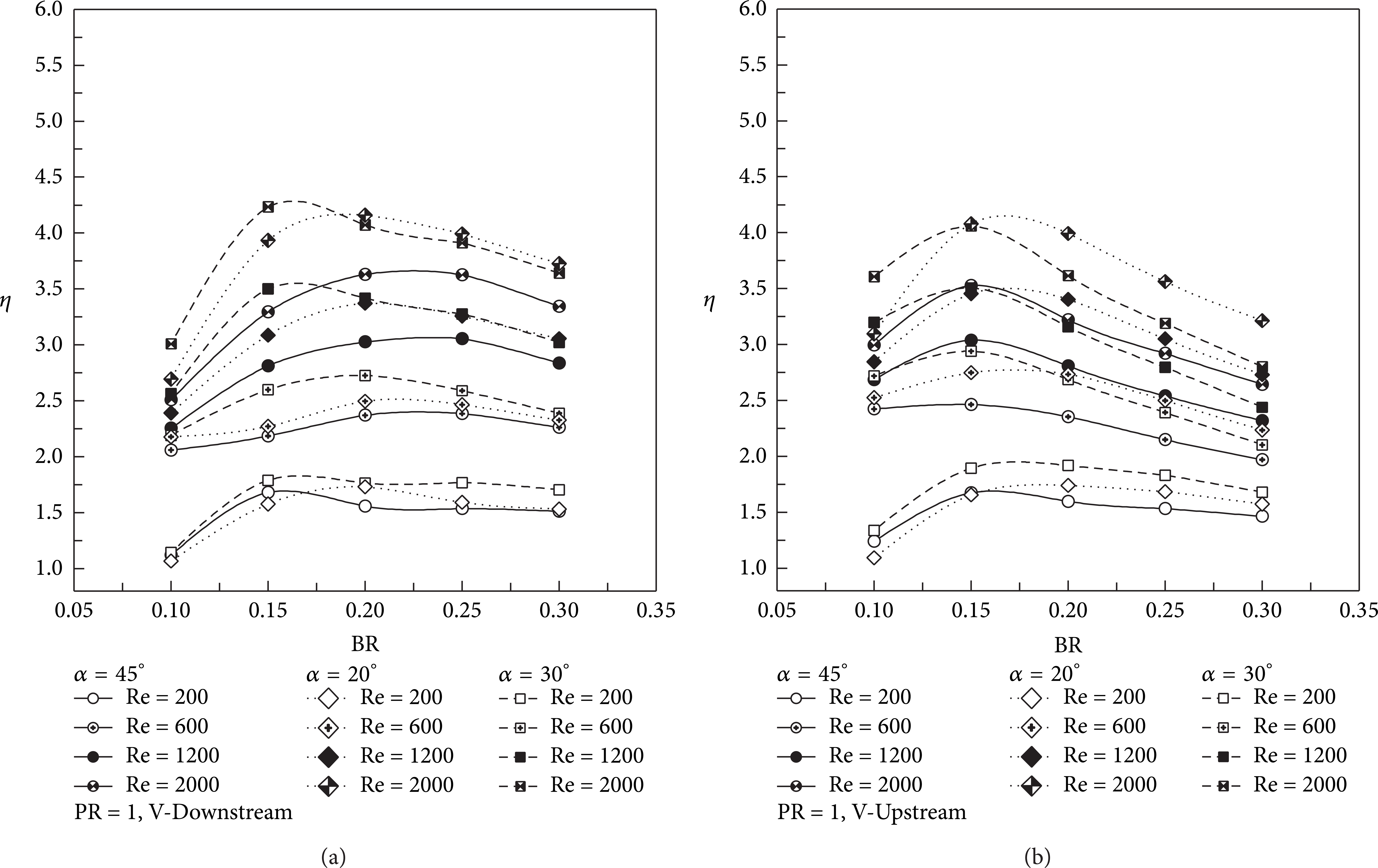
The variations of the η for 30° V-baffle with BR at various α and Re values: (a) V-Downstream and (b) V-Upstream.
4.6. Effect of Pitch Ratio
The different three pitch ratios, PR = 1.0, 1.5, and 2.0, at single BR = 0.20 with in-line arrangement are presented in Figures 15, 16, and 17, respectively, for the variations of Nu/Nu0, f/f0, and η at various Reynolds number and flow attack angles. The PR = 1 shows the maximum values of heat transfer and friction factor while the PR = 2 gives the lowest values for all flow attack angle cases. The heat transfer rates for PR = 2 with various flow attack angles are found to be similar values. In addition, the thermal enhancement factor values for PR = 1 are very close to PR = 1.5.

The variations of the Nu/Nu0 for 30° V-baffle with Re at various α and PR values: (a) V-Downstream and (b) V-Upstream.
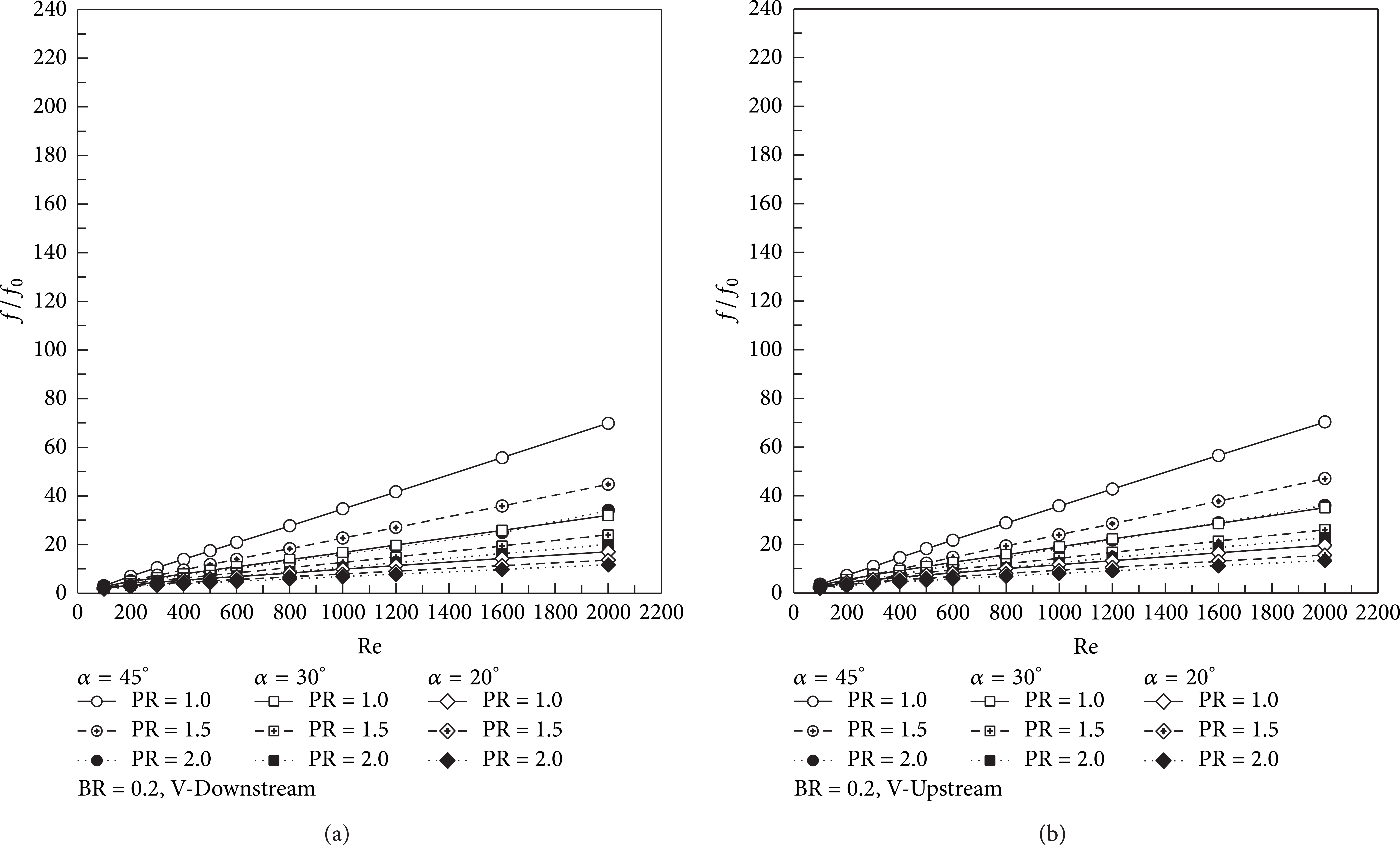
The variations of the f/f0 for 30° V-baffle with Re at various α and PR values: (a) V-Downstream and (b) V-Upstream.

The variations of the η for 30° V-baffle with Re at various α and PR values: (a) V-Downstream and (b) V-Upstream.
4.7. Effect of Flow Attack Angle
The flow attack angle is a main factor for improve heat transfer rate and thermal performance in the baffled square channel. The comparison of the flow attack angle is studied by comparing the numerical results with the previous work, 20° V-baffle [12] and 45° V-baffle [11] as displayed in Figures 12–17. In general, the 45° V-baffle provides the highest on both heat transfer rate and friction factor compared to the 20° and 30° V-baffles, especially at the highest BR, Re values and PR = 1. At BR = 0.3, Re = 2000, PR = 1, and V-Downstream cases, the 45° V-baffle gives a higher heat transfer rate around 22% and 61.42% than the 30° and 20° V-baffles, respectively, while the friction factor is found to be around 2.3 and 5.56 times higher than the 30° and 20° V-baffles, respectively. The 30° V-baffle gives higher heat transfer rate than the 20° V-baffle around 32.28%, while the friction factor of 30° V-baffle is found to be about 2.42 times higher than the 20° V-baffle, considering at BR = 0.3, Re = 2000, PR = 1 for V-Downstream. The numerical results indicate that the use of the 45° V-baffle results in the increasing heat transfer rate over the other cases, while the 20° V-baffle can help to reduce the pressure loss. As the thermal enhancement values, the optimum points are found on both 20° and 30° V-baffle cases around 4.25 when the 45° V-baffle gives the lowest value of thermal enhancement factor due to enlarged pressure loss.
4.8. Effect of Flow Direction
From [11, 12], it is found that the differences in flow direction, V-Downstream and V-Upstream, result in the difference of the flow configurations. The V-Downstream cases create the counter-rotating flow with common-flow-up while the V-Upstream cases lead to the counter-rotating flow with common-flow-down. Therefore, the impingements of fluid flow are found at different area. The peaks of heat transfer rate appear at the sidewalls of the square channel for V-Downstream cases, while the V-Upstream cases are found at the upper and lower walls of the square channel. Figures 18(a) and 18(b) show the variations of the Nu/Nu0 with Reynolds number on the walls of the V-Downstream and V-Upstream, respectively, for 30° V-baffle at PR = 1. As seen, the sidewall of the V-Downstream case gives higher heat transfer rate than the upper wall, while the peak regimes for V-Upstream case is found at the upper and lower walls of the square channel. These results confirm that the heat transfer characteristics and the flow configurations for 30° V-baffle are similar trends as 20° and 45° V-baffle.

The variations of the η for 30° V-baffle with Re at various α and PR values: (a) V-Downstream and (b) V-Upstream.
4.9. The Prediction of the Thermal Enhancement Factor and Empirical Correlations for V-Baffle
As the numerical results, it is found that the maximum thermal enhancement factor is found at the Re = 2000 for all cases. Consequently, the relationships between the blockage ratio and pitch ratio in terms of η contour with Re = 2000 for V-Downstream and V-Upstream are presented in Figures 19(a) and 19(b), respectively, for prediction of the maximum thermal enhancement factor in the range studied and also help to design the heat exchanger system. As figures, the V-Downstream gives the maximum thermal enhancement factor around 4.8 at PR = 1.1–1.6 and BR = 1.5–1.9, while the V-Upstream leads to the highest thermal enhancement factor around 4.3 at PR = 1.2–2.0 and BR = 0.1–0.14.
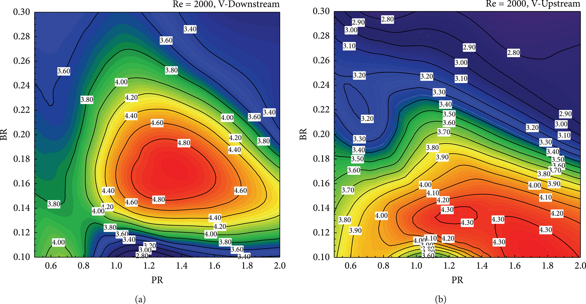
The η contour for 30° V-baffle at different BR and PR values at Re = 2000 for (a) V-Downstream and (b) V-Upstream.
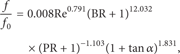
The relationships between BR, Re, and η for the 30° V-baffle of V-Downstream and V-Upstream are displayed in Figures 20(a) and 20(b), respectively. The empirical correlations for the 20°, 30°, and 45° V-baffles in the square channel are reported in (12)–(15), for BR = 0.1–0.3, PR = 1–2, and Re = 100–2000. The results from the correlation and the prediction are found to agree well within ±15% on both heat transfer and friction factor:


for V-Downstream, BR = 0.1–0.3, PR = 1–2, Re = 100–2000, and α = 20°–45°, and

for V-Upstream, BR = 0.1–0.3, PR = 1–2, Re = 100–2000, and α = 20°–45°.

The relationship between BR, Re, and η at various PRs of 30° V-baffle for (a) V-Downstream and (b) V-Upstream.
5. Conclusions
The investigations on the thermal performance evaluations of the 30° V-baffles in an isothermal wall square channel and the empirical correlations are presented. The influences of arrangements, flow directions, blockage ratios, and pitch ratios are studied and compared with the previous works, 20° and 45° V-baffles. The main findings from the numerical results are as follows.
The 30° V-baffles can produce the flow configurations and heat transfer behaviors similar to the 20° and 45° V-baffles. The flow configurations, four main vortex flows with small vortices at the corner of the square channel, for the V-baffle are found. The counter-rotating flows with common-flow-up and common-flow-down from V-Downstream and V-Upstream, respectively, are created from V-baffles. The peaks of heat transfer are seen at the sidewalls of the square channel for V-Downstream cases, while the V-Upstream cases are found on both the upper and lower walls of the square channel. The fully developed periodic flow and heat transfer profiles appear around the 7th–8th module while the periodic flow and heat transfer profiles are produced at 2nd module in all cases.
The in-line case gives higher heat transfer rate and thermal performance than the staggered case when BR > 0.2.
The increasing Reynolds number BR and reducing PR values lead to the rise of heat transfer rate and friction factor for all cases. In range studied the 30° V-baffle gives 1–17 times and 1–14 times higher heat transfer rate than the smooth square channel for V-Downstream and V-Upstream, respectively. The pressure loss values are found to be maximum around 100 and 110 times higher than the plain channel with no baffle for V-Downstream and V-Upstream, respectively. The optimum thermal enhancement factor at the highest Reynolds number is about 4.25 for V-Downstream at BR = 0.15 while the V-Upstream is around 4.0 in case of BR = 0.20.
The 45° V-baffle performed the highest on both heat transfer rate and friction loss while the 20° V-baffle can help to reduce the pressure. The 30° V-baffle is a compromised point between the 45° and 20° V-baffles which give lower pressure loss than the 45° V-baffle while the thermal performance are similar as the 20° V-baffle.
The contour plots of thermal enhancement factor at various BR and PR values at Re = 2000 show the highest thermal enhancement factor around 4.8 and 4.3 for V-Downstream and V-Upstream, respectively. The correlations and design charts that help to precalculate for various heating systems such as electronic equipment, microchannel, and air condition are also reported.
Footnotes
Nomenclature
Conflict of Interests
The authors declare that there is no conflict of interests regarding the publication of this paper.
Acknowledgments
The funding of this work is provided by King Mongkut's Institute of Technology Ladkrabang, Thailand. The authors would like to thank Associate Professor Dr. Pongjet Promvonge for suggestions.