
Abstract
We present a distributed algorithm for creation of geometric spanners in a wireless sensor network. Given any connected network, we show that the algorithm terminates in
1. Introduction
From a communications perspective, a wireless sensor actuator network can be modeled as a graph
In this paper, we present FLOC-SPANNER, a distributed, locally self-stabilizing algorithm for creation of geometric spanners. Our algorithm is built on top of FLOC [1], a locally, self-stabilizing algorithm for creation of solid-disk clusters in wireless sensor networks. In summary, FLOC partitions a wireless network into clusters such that all nodes within a certain radius around each clusterhead, necessarily, belong to that cluster. This ensures that neighboring clusterheads are separated by a certain distance and also allows roughly uniform distribution of clusters and cluster-sizes across the network. While maintaining this solid-disk property, FLOC also ensures that node additions and deletions do not result in a global reformation of clusters by allowing a dilation factor m of at least
While FLOC creates clusters in the network, there are no structures established for connecting these clusters and enabling communication between clusters. As a result, the clusters by themselves do not form a connected subgraph. Establishing a sparse but sufficient set of connections between the clusters and thus realizing a spanner graph is not trivial. This is because there are potentially a large number of candidate pairs between neighboring clusters that can form connecting links between neighboring clusters and the challenge is to avoid redundant connections while still ensuring that the graph remains connected. The algorithm FLOC-SPANNER presented in this paper addresses this challenge and creates a geometric spanner by establishing sparse, yet sufficient connections between clusters created by FLOC. Figure 1 illustrates a spanner graph created using our algorithm on a 10 by 10 grid.

Illustration of a spanner graph created on a 10-by-10 Grid with FLOC-SPANNER. The bold edges represent the intercluster connections while the lighter edges represent the links from clusterhead to cluster members.
The key characteristics of our proposed algorithm are summarized below.
During creation of connections between clusters, we maintain the property that if two nodes a and b are used to connect clusters We piggyback entirely on the periodic and low frequency maintenance messages of the underlying clustering algorithm to establish as well as maintain the spanner structure. As a result no further messaging overhead is needed for FLOC-SPANNER. Note that FLOC creates clusters in Unlike several other algorithms for spanner creation, FLOC-SPANNER does not require location information for its operation. This makes deployment easier. The upper bound on the path stretch factor in the resulting spanner is shown to be Utilization of FLOC for clustering also ensures that impact of link changes (additions or removals) is contained within a bounded distance from the source of the event. The resulting spanner structure can be used for broadcasting system-wide state information in a one-to-all as well as all-to-all mode. Furthermore the upper bound on the path stretch factor ensures that, even in a broadcast mode, information can be transferred in time proportional to the shortest path between two nodes. This property of distance-sensitivity is significant for many querying, tracking, and control applications of wireless sensor actuator networks [2–4].
We analyze the performance of FLOC-SPANNER using large scale simulations in JProwler, a discrete event simulator for wireless sensor networks. Specifically, we measure the path stretch factor, number of spanner edges, and the time for spanner creation under different network sizes ranging from
2. Model
2.1. Network Model
We consider a wireless ad hoc network in which nodes lie on an undirected graph topology. Nodes are assumed to be identical in their processing, data transmission, and reception capacity. We assume a dual-band model for the radio range; that is, the nodes are considered to be in either inner-band or outer-band region. A node can communicate reliably with nodes that are in the inner-band range and unreliably with nodes that are in outer-band range. A similar model is assumed in [1]. This is a reasonable assumption to make considering that wireless radios have been shown to exhibit a dual-band characteristic in which received signal strengths are significantly high and isotropic within an inner band and exhibit high variance (due to time-varying interference and multipath effects) in an outer band [5]. Unit distance is defined as the i-band range of each node. Nodes can locally determine whether a neighbor is within the i-band by using received signal strength, time of flight, or ultrasound based techniques. The network graph consisting of only i-band links is assumed to be connected. Each node has access to local timers that are used for the tasks such as sending of heartbeats periodically and for timing out when waiting on a condition. The network is not required to be synchronized in time.
2.2. Execution Semantics
Nodes have unique ids. We use i, j, and k to denote the nodes and

A guard is a Boolean expression over variables. An assignment statement updates one or more variables. A state is defined by a value for every variable in the program, chosen from the predefined domain of that variable. An action whose guard is true at some state is said to be enabled at that state and is executed.
2.3. Clustering
Each node runs an underlying clustering algorithm FLOC. By doing so, within
2.4. Problem Statement
Before stating the objective, we first note the following definition for neighboring clusters.
Definition 1 (neighboring clusters).
Two clusters X and Y are neighboring if there exist nodes i and j within i-band of each other such that
The objective in this paper is to utilize the underlying clustering and create a spanner in the network which ensures the following properties:
all neighboring clusters are connected and thus the graph is connected; if two nodes i and j connect clusters if two nodes i and j connect clusters
These properties ensure that the network graph is connected using reliable links while also ensuring that unnecessary connections between neighboring clusters are avoided. We show in our analysis that this results in retaining only
2.5. Fault Model
Nodes may fail, stop, and crash and new nodes may join the network. The states of a node may be arbitrarily corrupted. In addition, messages may be lost. These faults can occur in any finite number, at any time, and in any order. A program is self-stabilizing if and only if, after faults stop occurring, the program eventually recovers to a state from where its specification is satisfied. A self-stabilizing program is fault-local self-stabilizing if the time and number of messages required for stabilization are bounded by functions of perturbation size rather than network size [1]. The perturbation size for a given state is the minimum number of nodes whose state must change to achieve a consistent state of the network.
2.6. FLOC Review and Addition of Spanner State
FLOC (fault-local clustering) [1] partitions a multihop wireless network into nonoverlapping and approximately equal-sized clusters such that all nodes within a certain radius around each clusterhead, necessarily, belong to that cluster. While maintaining this solid-disk property, FLOC also ensures that node additions and deletions do not result in a global reformation of clusters by allowing a dilation factor m of at least
Action 1. When the node has been idle for some random time, it changes its state to candidate (i.e., becomes a potential candidate for becoming the clusterhead) and broadcasts a candidacy message.
Action 2. If the candidacy message is received by a node in the i-band region of the sender and the receiver is already an i-band member of some existing cluster, the receiver sends a conflict message.
Action 3. If the candidate node receives the conflict message for its candidacy request, it becomes an o-band member of the cluster of the node which sent the message.
Action 4. When the candidate node does not receive a conflict message within a certain predefined time the node becomes a clusterhead and announces the same.
Action 5. Any node in the idle state that receives a clusterhead message becomes an i-band or o-band member of the cluster based on determination of i-band/o-band status of the sender.
Action 6. A node in o-band region of some cluster receives leader message and determines that it is in i-band range of the node which sent the message and joins that cluster as i-band member.
FLOC thus exploits the atomic broadcast property of wireless networks to enable unique election of clusterheads. By atomically informing the neighbors of its intention to become a clusterhead through a broadcast message, a node is able to lock itself into the position of a clusterhead unless it is notified of conflicts explicitly. It has been shown in [1] that these actions result in creation of solid-disk clusters within
The original actions of FLOC only focused on forming cluster membership; in this paper we are also interested in realizing a connected subgraph which is a spanner for the graph. Hence, after becoming a cluster member we add a variable
3. FLOC-SPANNER Protocol
In this section we describe the FLOC-SPANNER protocol and analyze its correctness. The actions are described for a given node j. The actions of this protocol at any node j are enabled as soon as the node becomes either an i-band or o-band member of some cluster using the FLOC protocol. Clusterhead nodes do not execute the actions of this protocol. Thus, a common precondition for all the guards in this program is that the node is either an i-band or o-band member. Note that all messages that are required for FLOC-SPANNER are piggybacked on periodic heartbeat messages sent out by every node to maintain cluster status. Thus there is no additional messaging overhead incurred.
3.1. Variables
Each node j maintains the following variables.
Monitor: in this state, the node is not competing to establish a connection with any other node. Conncand: in this state, the node is ready to compete for connection establishment and is waiting for the next heartbeat message to send the request. Initiator: this is the verification state for a node that has sent a request for connection establishment and is waiting to learn about conflicts, that is, other existing connectors that are within its i-band range. Receptor: this is the verification state of a node which has received a request for connection establishment and is waiting to learn about conflicts, that is, other existing connectors that are within its i-band range.
3.2. Program
We describe the algorithm by grouping together the guard-action pairs in each of the

(a) State transition diagram, (b) list of states, and (c) list of transition events: note that events e and f are expected to happen concurrently at nodes in the initiator and receptor states corresponding to a connection.
3.2.1. Monitor State
The actions executed in the monitor state are shown in Algorithm 1 using guard-action pairs. A node is in the monitor state whenever it is not competing to form a connection with a neighboring cluster. In the monitor state, a node periodically beacons its heartbeat message announcing its current state. The transition of a node to other states is guided based on the messages that are received. These transitions are summarized below.
update Add x to
(1) Heartbeat Timer Timeout. In the monitor state, when the heartbeat timer expires it sends a heartbeat message which contains its cluster id (
(2) Receive Heartbeat Message. The actions taken by the node when it receives a heartbeat message depend on the state of the node from which it is received. The actions are grouped as follows.
Receive heartbeat from node k which belongs to the same cluster as j (i.e., Receive heartbeat from node k belonging to different cluster and the message is of type T_REGULAR: node j checks if there is already another connector to k's cluster within j's i-band range; that is, it checks if
It becomes a candidate to establish connection with k's cluster via k and changes its state to conncand. The node id k and its cluster Receive heartbeat from node k belonging to different cluster and the message is of type T_INITIATE: when the node j receives the connection initiation message it does the following provided that there is no other connector to k's cluster within j's i-band range; that is,
The node changes its state to receptor. The node id k and its cluster The node resets its heartbeat timer so that it gets one full heartbeat interval to learn if there are other confirmed connections within its i-band range.
3.2.2. Conncand State
The actions executed in the conncand state are shown in Algorithm 2 using guard-action pairs. A node moves to the conncand state when it learns about a new neighboring cluster and is not aware of existing connections to that cluster. In the conncand state, it waits until the next heartbeat timeout to initiate a connection with the neighboring cluster. Until that time it listens to heartbeat messages from neighbors to learn about already existing connections and connection requests from other nodes in its cluster. These actions are summarized below.
(1) Receive Heartbeat Messages. During the conncand state, node j checks all incoming heartbeat messages if there are existing connections with
(2) Heartbeat Timer Timeout. When the node heartbeat timer times out and it is in conncand state the node j does the following.
It sends heartbeat message and piggybacks a connection request to the node It changes its state to initiator.
3.2.3. Initiator State
The actions executed in the initiator state are shown in Algorithm 3 using guard-action pairs. The initiator state represents the state where a node has initiated a connection request with a node in its neighboring cluster. It waits for an entire heartbeat interval to learn about conflicting connections between the same pair of clusters by listening to heartbeat messages. Only if no conflicts are detected, the node will confirm the connection and move to the monitor state. Otherwise, the connection request will be canceled. The actions of a node in in the initiator state are summarized below.
Add
(1) Receive Heartbeat Messages. During the initiator state, node j checks all incoming heartbeat messages if there are existing connections with Receive heartbeat from node k which belongs to the same cluster as j (i.e.,
(a) It sends heartbeat message indicating conflict to the receptor node stored in the (b) It resets its heartbeat timer. (c) It changes its state to monitor. Receive heartbeat from node k belonging to
(a) It sends heartbeat message indicating conflict to the receptor node stored in the (b) It resets its heartbeat timer. (c) It changes its state to monitor. Receive heartbeat from node
(a) Node (b) Node (c) Node The variables
(2) Heartbeat Timer Timeout. When the heartbeat timer of a node which is in initiator state times out while node j is still in the initiator state, it means that the node j has not learned about any other connectors to
3.2.4. Receptor State
The actions executed in the receptor state are shown in Algorithm 4 using guard-action pairs. A node moves to the receptor state when it receives a connection initiation from a node in the neighboring cluster. It waits for an entire heartbeat interval to learn about conflicting connections between the same pair of clusters by listening to heartbeat messages. Only if no conflicts are detected, the node will confirm the connection and move to the monitor state. Otherwise, it will send a heartbeat message indicating conflict and reset its heartbeat interval.
Add
(1) Receive Heartbeat Messages. During the receptor state, node j checks all incoming heartbeat messages if there are existing connections with Receive heartbeat from node k which belongs to the same cluster as j (i.e.,
It sends heartbeat message indicating conflict to the initiator node stored in the It resets its heartbeat timer. It changes its state to monitor. Receive heartbeat from node k belonging to
It sends heartbeat message indicating conflict to the initiator node stored in the It resets its heartbeat timer. It changes its state to monitor. Receive heartbeat from node
Node Node
(2) Heartbeat Timer Timeout. When the heartbeat timer of a node which is in receptor state times out while node j is still in the receptor state, it means that the node j has not learned about any other connectors to
3.3. Analysis
The FLOC-SPANNER protocol creates a geometric spanner by connecting all pairs of neighboring clusters created by FLOC. In this section, we analyze the correctness of the FLOC-SPANNER protocol and provide bounds on completion time and the path stretch factor. We first state the invariants for the program.
Lemma 2.
The following invariant holds for FLOC-SPANNER.
For any two nodes i and j belonging to the neighboring clusters x and y Given nodes i, j, and k such that i and j lie within i-band of each other and belong to the same cluster x, and node k belongs to a neighboring cluster y
Proof.
(I1) states that for a connection to be successful both the nodes involved in the connection should connect to each other; that is, if node i of one cluster, connects to the node j of neighboring cluster, then node j should also connect to the node i. This ensures that one-sided connections will be avoided. In the FLOC-SPANNER protocol, as soon as a node discovers a neighboring cluster that is not in its list
(I2) states that if there is a connection between two clusters, then there exists no other connection between the same clusters within the inner-band range of the nodes that are involved in the connection. This property ensures that the number of pairwise connections used to establish the spanner graph is minimized. In the FLOC-SPANNER protocol, all nodes that learn about a new cluster through a heartbeat message move to the conncand state. However, However, only the node whose heartbeat timer first expires (say node i), initiates this connection. Other candidate nodes that hear a connection initiation or learn about an already existing connection between the clusters cancel their intention to form a connection. Furthermore, once an intention to form a connection has been announced, both the initiator and the corresponding receptor node (say node j) wait concurrently for one heartbeat interval to learn about connections within their respective i-band region. If such a conflicting connection exists, the nodes cancel their upcoming connection by sending a conflict message. Likewise, if any other node had initiated a connection between the same pair of clusters after the node i initiated the connection, the subsequent heartbeats sent out by i and j after confirmation of the connection will prevent the new initiation from succeeding. Thus, if a connection is established through a pair of nodes, then there exist no other connections between the same clusters through nodes within i-band region of either of these nodes.
Note that the above invariants assume that all messages are successfully received. In the presence of message losses, the invariants may be violated. For example, when the heartbeat message with an initiation request is lost, a partial connection may be established. When a heartbeat message with a conflict notification is lost, there could be duplicate connections within i-band region of each other. Handling of these invariant violations and self-stabilization to the invariant states are incorporated through monitoring of invariant states and recovery by means of the fault-tolerance actions that are described in Section 3.4.
Theorem 3.
Irrespective of network size, the FLOC-SPANNER protocol establishes connections between all pairs of neighboring clusters in
Proof.
First, consider a given pair of neighboring clusters x and y, that is, clusters which have at least one pair of nodes i and j, where
Secondly, if all pairs of neighboring clusters were connected by a different pair of connector nodes, then all the connection establishment can take place concurrently, thus terminating the process in
Theorem 4.
Let
Proof.
Recall from the description of FLOC in Section 2.6 that, for each node that is a member of a cluster,
Theorem 5.
The spanner graph
Proof.
Let
3.4. Fault-Tolerance Actions
Topology changes and message losses can cause the protocol's invariants to be violated. For example, (i) when nodes are removed, existing connections between neighboring clusters may be broken; (ii) when a heartbeat message with a connection initiation request is lost, a partial (one-sided) connection may be established; (iii) when a conflict message is lost, multiple connections may be established within the same pair of clusters that are within i-band of each other. To handle these invariant violations and to guarantee self-stabilization to the invariant states, we introduce the following actions which involve monitoring of the system state to detect invariant violation. These fault-tolerance actions are shown in Algorithm 5 using guard-action pairs.
A connection liveness timer is used to monitor the liveness of existing connections to neighboring clusters. The interval Violation of invariants due to message losses can be detected by checking for inconsistencies in the connection information. Specifically, whenever a node that is a connector to a cluster X receives a heartbeat message from a node k that belongs to the same cluster as j (i.e.,
remove x from
remove x from
remove x from
4. Performance Evaluation
We evaluate the performance of FLOC-SPANNER using JProwler, a Java based discrete event simulator for wireless sensor networks. We implement the underlying clustering protocol FLOC as well as the actions for the FLOC-SPANNER protocol as discussed in this paper. We use a static grid topology and consider networks of different densities and different sizes. Specifically, we have simulated networks of sizes
4.1. Convergence Time
To compute the convergence time for the protocol, we measure the number of connected paths that exist in the network at intervals of

(a) Convergence ratio as a function of time for different network sizes. (b) Average convergence time as a function of network size for different network densities.
Figure 3(a) is shown for the density model
4.2. Path Stretch Factor
To compute the path stretch factor, we compute the length of the shortest path using Dijkstra's algorithm on the original network graph and then on the spanner graph resulting from our protocol. The ratio of these lengths is taken as the path stretch factor. The ratio is computed only for paths that exist on the spanner graph. In Figure 4(a), we observe the variation in path stretch factor over time for the density model

(a) Path stretch factor as a function of time for different network sizes. (b) Path stretch factor as a function of network size, averaged over different densities.
4.3. Spanner Edges
In Figure 5(a), we show the total number of spanner edges in the system as a function of simulation time for the density model
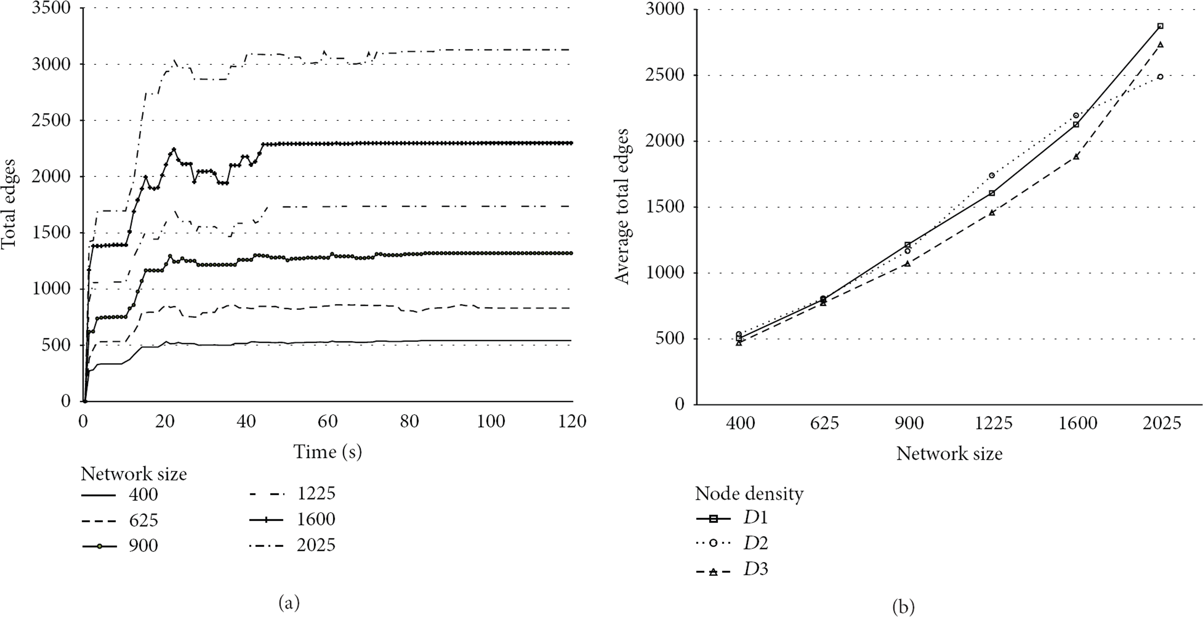
(a) Number of spanner edges as a function of time for different network sizes. (b) Number of spanner edges as a function of network size for different network densities.
5. Related Work
Designing algorithms for creation of spanners is a well-researched topic and some detailed surveys can be found in [6–8]. A brief summary is presented below.
From the perspective of wireless ad hoc networks, it is important to realize spanner structures in a distributed and local manner. In that context, relative neighborhood graphs [9] and Gabriel graphs [10] are examples of proximity graphs that can be realized in a distributed manner. However, both of these do not yield geometric spanners (constant bound on path stretch factor). Yao graphs [11] are an elegant generalization of proximity graphs that can be constructed locally and yield geometric spanners. The idea in Yao graphs is for each node to partition the space around it into sectors of angle
Delaunay triangulation of a network graph, a set of edges such that for each edge there is a circle containing the edge end points but not containing any other points, also yields a geometric spanner. However, a Delaunay triangulation graph could potentially require inclusion of edges that are longer than the transmission range (not feasible in a wireless sensor network). Hence restricted Delaunay graphs (RDGs) and variations of RDG (such as localized Delaunay triangles) have been used in the context of wireless networks for localized spanner creation. RDGs utilize only local communication links and result in geometric spanners. By utilizing RDGs, techniques in [16–18] produce spanner that contain only
The idea of first creating clusters and then connecting them to create geometric spanners has been exploited in [19]. Without the requirement of planarity, such an approach does not require localization and the idea in FLOC-SPANNER is along the same lines. However, the key difference arises from the process of creating the intercluster connections in a self-stabilizing manner with very little message overhead. The technique in [19] relies on first building the two-hop neighborhood of each node using synchronous rounds of communication, after which the intercluster connection is atomically established using some criteria such as nodes with minimum node id or maximum battery levels. Reestablishing and maintaining this structure in the presence of node additions/deletions and clustering changes are not trivial in this model and have not been discussed. In contrast, our solution is asynchronous and each node nominates itself as a candidate upon learning about any new cluster in its neighborhood. Yet, we ensure that there are no duplicate connections within the communication range of connector nodes by overhearing heartbeat messages and signaling a conflict before confirmation of connection. The proposed algorithm is thus able to dynamically react to topology changes, has lower memory requirement, converges in
The idea of exploiting the atomic broadcast characteristic of wireless networks to ensure that connections between clusters are separated by a minimum distance is similar to the idea used in FLOC to guarantee minimum cluster separation. However, it is to be noted that, in the process of clusterhead election, the conflict detection can be resolved entirely locally (i.e., within one hop of a candidate clusterhead). On the other hand, in the formation of cluster connectors, two nodes have to mutually agree that no conflicts exist within their respective locality and concurrently agree on the formation of the cluster connector. This imposes an additional challenge which is addressed in the FLOC-SPANNER protocol.
6. Conclusions
We presented FLOC-SPANNER, a distributed algorithm for creation of geometric spanners in a wireless sensor network. Our algorithm uses an underlying clustering algorithm as a foundation for creating spanners and only relies on the periodic heartbeat messages associated with cluster maintenance for the creation of the spanners. There is no extra overhead for spanner creation. Given any connected network, we showed analytically that the algorithm terminates in
We verified the performance of our algorithm using large scale simulations in JProwler, a java based discrete event simulator. Our simulations show that the average path stretch factor for routing along the spanner for large networks is less than
Footnotes
Conflict of Interests
The authors declare that there is no conflict of interests regarding the publication of this paper.