
Abstract
Dynamic reliability analysis of a filtering reducer is performed by accounting for discrete shocks from the space environment. Gears are considered as the lumped mass and meanwhile the meshing between different gears is equivalent to a dynamic system consisting of springs and dampers during construction of the dynamic model. The Newmark method is employed to resolve differential equations, and then the additional acceleration could be obtained, caused by shocks to the filtering reducer. Dynamic reliability analysis is conducted with the help of the Simulink tool for the outputs. The results are hopefully useful for spacecraft mechanism design.
1. Introduction
The long duration life and high reliability for a spacecraft should be satisfied during the design stage in the space field. The complex functions and growing life of a spacecraft are mainly determined by the life and reliability of its mechanism. In other words, the transition system of a spacecraft is the key system which affects the life and reliability of the spacecraft [1]. Additional acceleration as a result of impact from space environmental factors, such as the meteoroid and space debris, will affect the transmission accuracy during the operation of the spacecraft in orbit. Soft failure is considered to occur when the produced transition error exceeds the predetermined value [2]. Studies on reliability analysis and design of a transition system are mainly based on statics principles in the current literatures. The reliabilities of some components, such as gear, shaft, rolling contact bearing, and spline, are calculated and then the reliability of a three-stage gear reducer is estimated based on the series-parallel function configuration [3]. The reliability of a gear transition system is analyzed while considering the single cylindrical gear reducer as the research objective [4]. Reliability-based design optimization models are built for all the parts of a 2 K-H planetary gear reducer [5]. A reliability-based design optimization model of the gear in the filtering reducer is established [6]. Actually, the transition system suffers a server impact from the dynamic characteristic and failures due to the dynamic characteristic are more likely to happen. In order to address these issues, the reliability associated with dynamic accuracy for the new type reducer, so-called the filtering reducer, under the discrete space environmental shocks is conducted. This will provide a theoretical foundation for its design to be consistent with the space environment.
The organization of the paper is as follows. The dynamic principle of the filtering reducer is briefly introduced in Section 2. The transformed dynamic model and determination of parameters are provided in Section 3. Dynamic reliability analysis under discrete space environmental shocks is illustrated in detail in Section 4 and followed by conclusions in Section 5.
2. The Working Principle of a Filtering Reducer
A filtering reducer is mainly composed of the following parts: the power input eccentric shaft, split dual external gears, fixed internal gear, and the power output gear. Split dual external gears are assembled in the eccentric section of the eccentric shaft and the external gear forms the coordination transition in the circumferential direction with the help of spline. The 3D model of the filtering reducer is given in Figure 1. The transition principle of a filtering reducer could be summarized as follows. First, the motor drives the eccentric shaft and the first-stage eccentric reducer mechanism is composed of the eccentric shaft, split dual external gears, and fixed internal gear to filter out the high-frequency wave of the rotation of the motor. Second, the second-stage filtering planetary drive mechanism with small teeth difference consists of split dual external gears and the power output gear to filter out the high-frequency wave of split dual external gears for driving the actuating mechanism in a slow speed. We can see from the configuration and working principle that the filtering reducer expresses the characteristics of multitooth meshing, compact conformation, bigger reduction ratio, small volume, and so on.
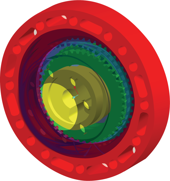
The 3D model of a filtering reducer.
3. Dynamic Model and Determination of Parameters
3.1. Dynamic Model
According to the working principle of a filtering reducer, the corresponding dynamic model is shown in Figure 2. The bigger one of the split dual external gears (named gear 3) and the fixed gear (named gear 2) constitute the first stage transition mechanism. Gear 3 and gear 2 are considered as lumped mass and the meshing between the two gears is treated as the combination of springs and dampers to form the one-degree-of-freedom vibratory system. Space environmental shocks act on the eccentric shaft. Since the eccentric shaft drives gear 3 to rotate, the shocks are equivalent to act on the gear 3, shown in Figure 2(a). Similarly, the smaller one of the split dual external gears (named gear 4) and the power output gear (named gear 5) constitute the second stage transition mechanism and the responding one-degree-of-freedom vibratory system is shown in Figure 2(b).

The dynamic model of two meshing parts.
Gears 3 and 4 form the split dual external gears in a whole and therefore they follow the same movement rule. With integrating the one-degree-of-freedom vibratory systems in Figures 2(a) and 2(b), the equivalent two-degree-of-freedom vibratory system for the filtering reducer is provided in Figure 3.

Two degrees of freedom of vibration system.
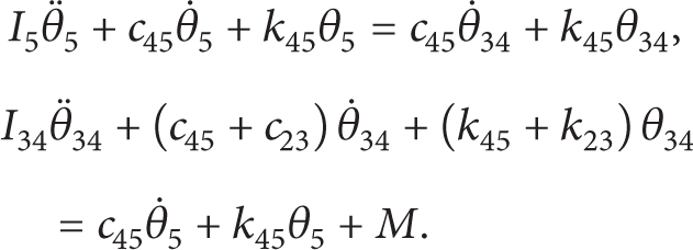
Where M stands for the mass of space environmental shocks, I34 and I5 are moments of inertia of split dual external gears and the power output gear, respectively; k23 is the meshing stiffness between the split dual external gears and fixed internal gear; k45 is the meshing stiffness between the split dual external gears and the power output gear; c23 is the meshing damping between the split dual external gears and fixed internal gear; c45 is the meshing damping between the split dual external gears and the power output gear; θ34 and θ5 are displacement angles of split dual external gears and the output gear;
The differential equations of the dynamic model of the filtering reducer are then derived based on Newton's second law of motion [7]:
3.2. Determination of Parameters
3.2.1. Determination of Moment of Inertia of Components
In order to calculate the moment of inertia of a hollow cylinder around the central axis, the related relationship of parameters of a hollow cylinder is shown in Figure 4.

Moment of inertia of a hollow cylinder.
ρ, R1, R2, and L stand for density, internal diameter, external diameter, and length of the hollow cylinder, respectively.
A thin cylindrical shell at the radius r is taken with the thickness dr and length L. Then the mass of the small part is dm = ρdV = ρ(2πrLdr), and the moment of inertia is

An approximate transformation is made from the gear to a hollow cylinder, where the pitch diameter of the gear is taken as the outer diameter of a hollow cylinder. Then the moment of inertia of gear 3 could be calculated based on the approximate transformation.
Provided that ρ = 7.7 g/cm3, L = 3.5 mm, R2 = 24 mm, and R1 = 15 mm, I3 = 1.19 × 10⁻⁵ kg·m2 can be obtained; provided that ρ = 7.7 g/cm3, L = 3.5 mm, R2 = 22.5 mm, and R1 = 15 mm, I4 = 8.7 × 10⁻⁶ kg·m2 can be obtained; provided that ρ = 7.71 g/cm3, L = 5 mm, R2 = 28 mm, and R1 = 25 mm, I5 = 1.36 × 10⁻⁵ kg·m2 can be obtained. Because gears 3 and 4 are a whole unit, I34 = I3 + I4 = 2.06 × 10⁻⁵ kg·m2.
3.2.2. Determination of the Average Stiffness and the Average Damping
A certain function exists between the average meshing stiffness k m and coefficient of engagement ε of the spur gear transmission. For the filtering reducer, coefficient of engagement ε is supposed to be 1.4 and k m = 5.52 × 10⁸ N/m [8]. In order to consider that the impact of shocks is torque, the equivalent stiffness associated with the rotation angle is expressed as k = k m ·R. The equivalent stiffness k23 and k45 can be provided as follows:

The meshing damping coefficient could be expressed as
3.2.3. Determination of Equivalent Shocking Loads
Shocks affecting the performance of the filtering reducer in the space orbit can be from two sources: the natural background dust (also called micrometeoroid, MM) and the orbital debris (OD) from human activity in space. Even though the mass of either MM or OD is slightly small, the huge moment due to the higher velocity will affect the safety and transition accuracy of the filtering reducer, especially the transition accuracy. Based on the above-mentioned analysis, it is essential to study the impact of shocks on the transition accuracy of the filtering reducer, mainly on the produced additional torque.
Shocking loads force on the eccentric shaft and the forced range is the circumference of the eccentric shaft. The arriving time between two successive shocks is approximate to be equal, and the cumulative damage is considered. In other words, the impact is calculated for all the shocks until the current time, shown in Figure 5.
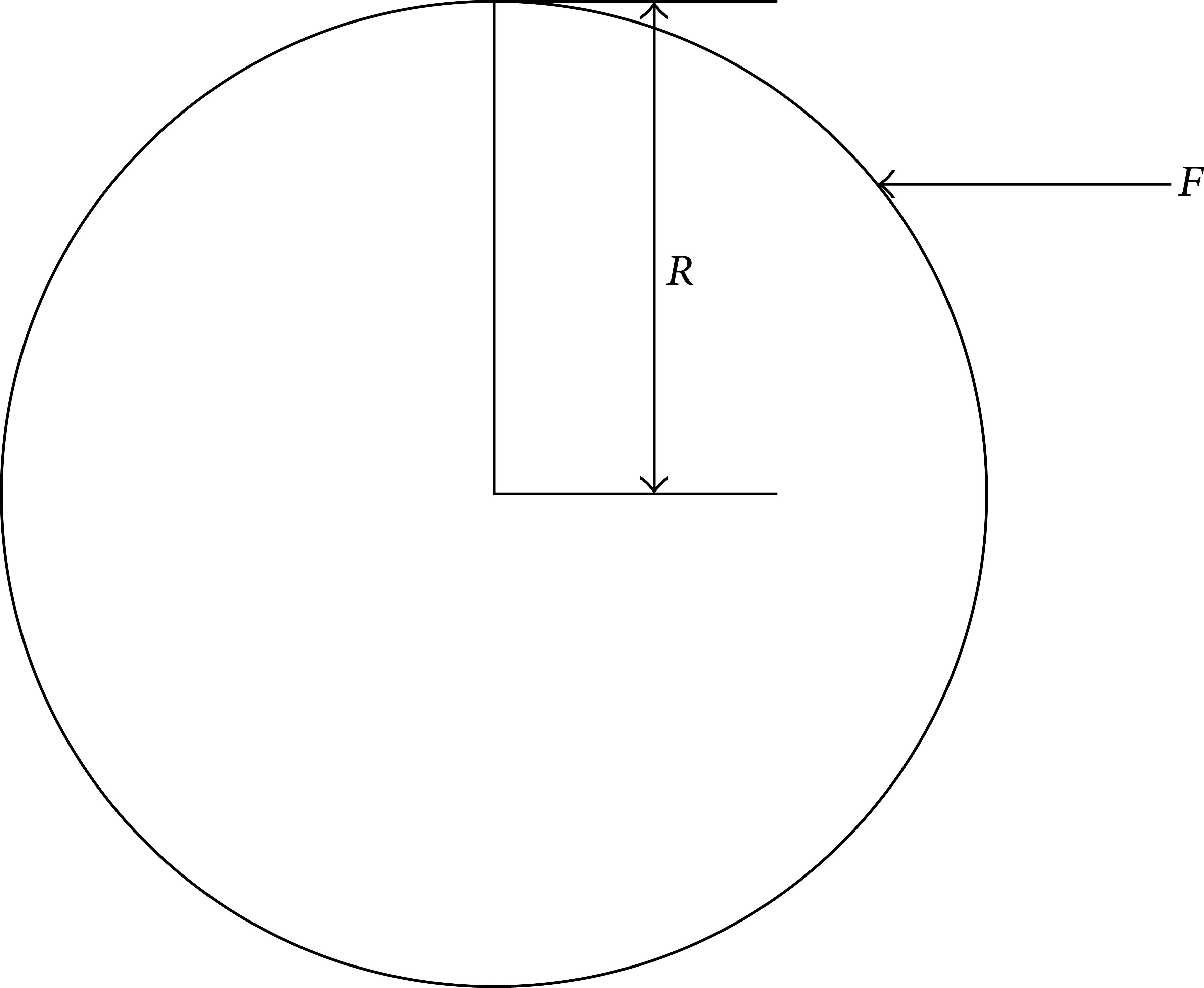
The effect of shocking on the eccentric shaft.
According to the law of conservation of momentum, the momentum of shock is FΔt = m(v t − v0), provided that the impact time Δt = 0.05 s, the mass m = 10−5 kg, the initial velocity v0 = 2 × 10⁴ m/s, and the final velocity v t = 0 m/s [10]. Then the force could be computed as F = mv0/Δt = 4 N and the biggest additional torque is M = F·R = 0.04 N·m. According to the randomness of shocks, the equivalent torque M is uniformly distributed with M~U(0, 0.04) N·m.
4. Dynamic Reliability Analysis of the Filtering Reducer
Newmark method is used to solve the differential equations composed of (1). With accounting for the uncertainty affecting the performance of the filtering reducer, k45 and c45 are assumed to follow normal distribution k45~N(1.38 × 107,1.38 × 106) and c45~N(2.74, 0.274), respectively. The output performance is the additional acceleration, which is used to describe the transition accuracy. We use Matlab Simulink tool to simulate the relationship between the inputs and output, shown in Figure 6.
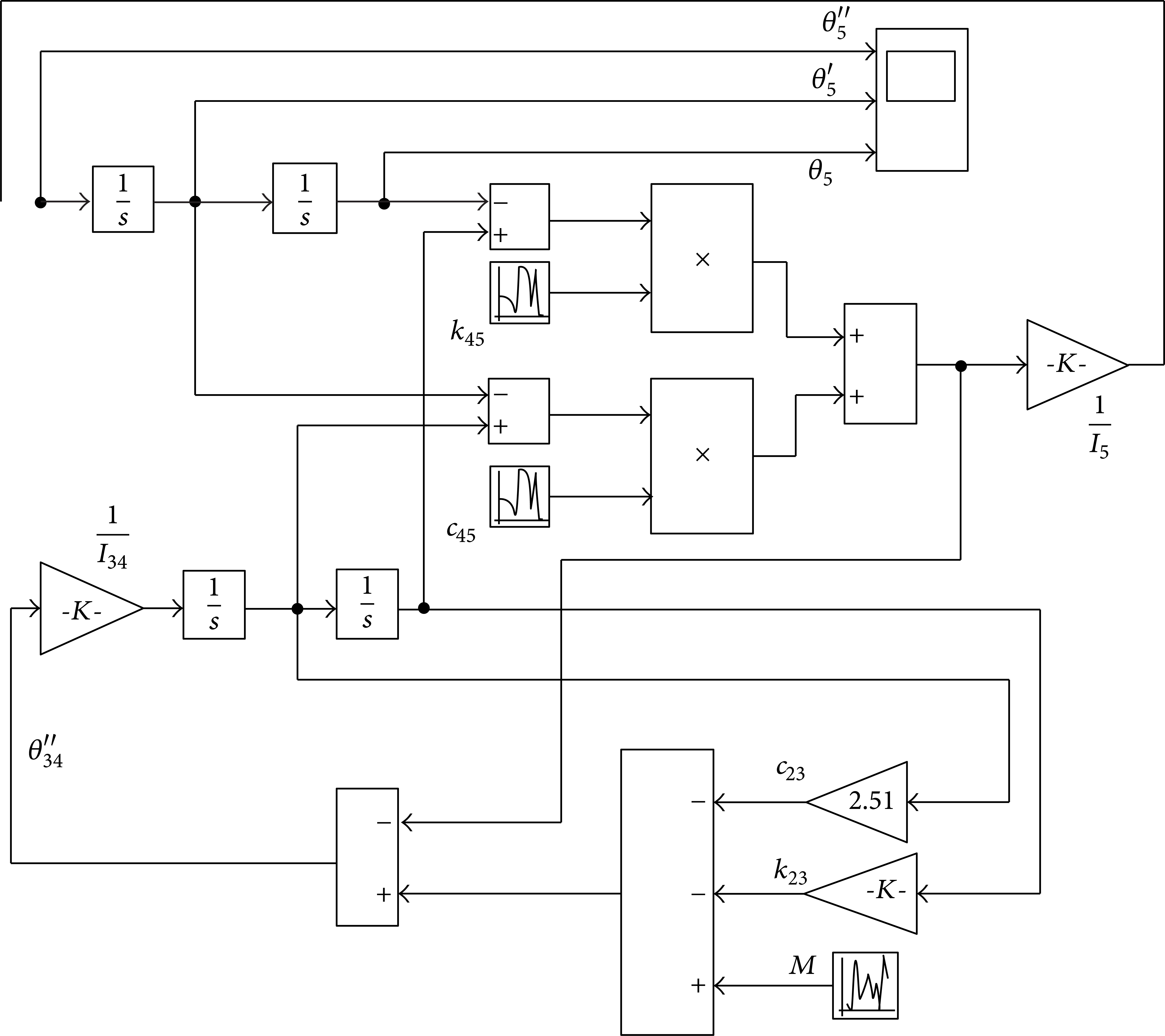
The simulation model with Simulink.
In order to characterize the additional angular acceleration, 100 samples are simulated during 100 seconds and the additional angular acceleration is obtained. The maximum additional angular acceleration is concerned during the actual operational time and when it exceeds the predetermined value, the system is considered to fail (soft failure).
In order to analyze the randomness for conducting reliability analysis, the maximum additional angular acceleration for 100 simulations during 100 seconds is recorded in Figure 7.

The maximum additional angular acceleration of 100 simulations.
Since the maximum additional angular acceleration during the operational time of 100 seconds is used, the extreme value distribution is used to describe the lifetime of the filtering reducer. Weibull distribution as a representative of the extreme distribution is utilized [11, 12]. The probability density function (PDF) of the Weibull distribution could be derived with the data recorded in Figure 7 and expressed by

The corresponding PDF is shown in Figure 8.

PDF of Weibull distribution.
With giving the failure threshold ϖ, the predetermined maximum additional angular acceleration, the PDF is calculated as

The probability of failure under different failure threshold ϖ is given in Table 1 and also in Figure 9.
The relationship between P f and ϖ.


The relationship between P f and ϖ.
We can see from Figure 9 that P f decreases with the increasing of ϖ. When ϖ = 0, the probability of failure is 1; when ϖ > 1200, the probability of failure is equal to 0.
5. Conclusions
In this paper, the dynamic model of the filtering reducer is built by considering the effect of shocks on the performance where the gear meshing is equivalent to spring and damper. The simulation of dynamic model is analyzed with the Matlab Simulink tool for obtaining the output. Considering the randomness of the inputs and consequentially the output, the dynamic reliability with Weibull distribution is conducted and further the probability of failure under different failure threshold is provided. The results of the study will be helpful in improving the design quality and extend the life duration time of spatial mechanisms, which will also provide the theoretical foundation for designing the protection equipment of spatial mechanisms.
Conflict of Interests
The authors declare that there is no conflict of interests regarding the publication of this paper.
Footnotes
Acknowledgments
This research was partially supported by the China Postdoctoral Science Foundation under the Contract no. 2013T60838 and the Vocational Education Research of Education Science “Twelve Five” Plan of Chongqing under the Contract no. 2013-ZJ-076.